1990 MITSUBISHI SPYDER service
[x] Cancel search: servicePage 734 of 2103
INTAKE AND EXHAUST Exhaust Manifold ENGINE (Turbo)>
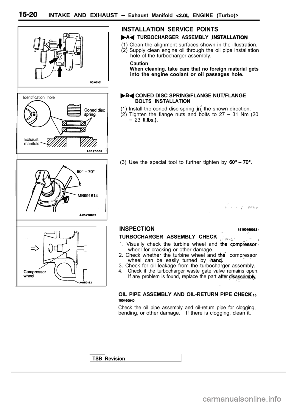
Identification holeExhaust
manifold
INSTALLATION SERVICE POINTS
TURBOCHARGER ASSEMBLY
(1) Clean the alignment surfaces shown in the illus tration.
(2) Supply clean engine oil through the oil pipe in stallation
hole of the turbocharger assembly.
Caution
When cleaning, take care that no foreign material g ets
into the engine coolant or oil passages hole.
CONED DISC SPRING/FLANGE NUT/FLANGE
BOLTS INSTALLATION
(1) Install the coned disc spring the shown direction.
(2) Tighten the flange nuts and bolts to 27
31 Nm (20
23
(3) Use the special tool to further tighten by
INSPECTION
TURBOCHARGER ASSEMBLY CHECK . .
1. Visually check the turbine wheel and
wheel for cracking or other damage.
2. Check whether the turbine wheel and
compressor
wheel can be easily turned by
3. Check for oil leakage from the turbocharger asse mbly.
4.Check if the turbocharger waste gate valve remains open.
If any problem is found, replace the part
.
OIL PIPE ASSEMBLY AND OIL-RETURN PIPE
Check the oil pipe assembly and oil-return pipe for clogging,
bending, or other damage. If there is clogging, clea n it.
TSB Revision
Page 740 of 2103
INTAKE AND Pipe and Main
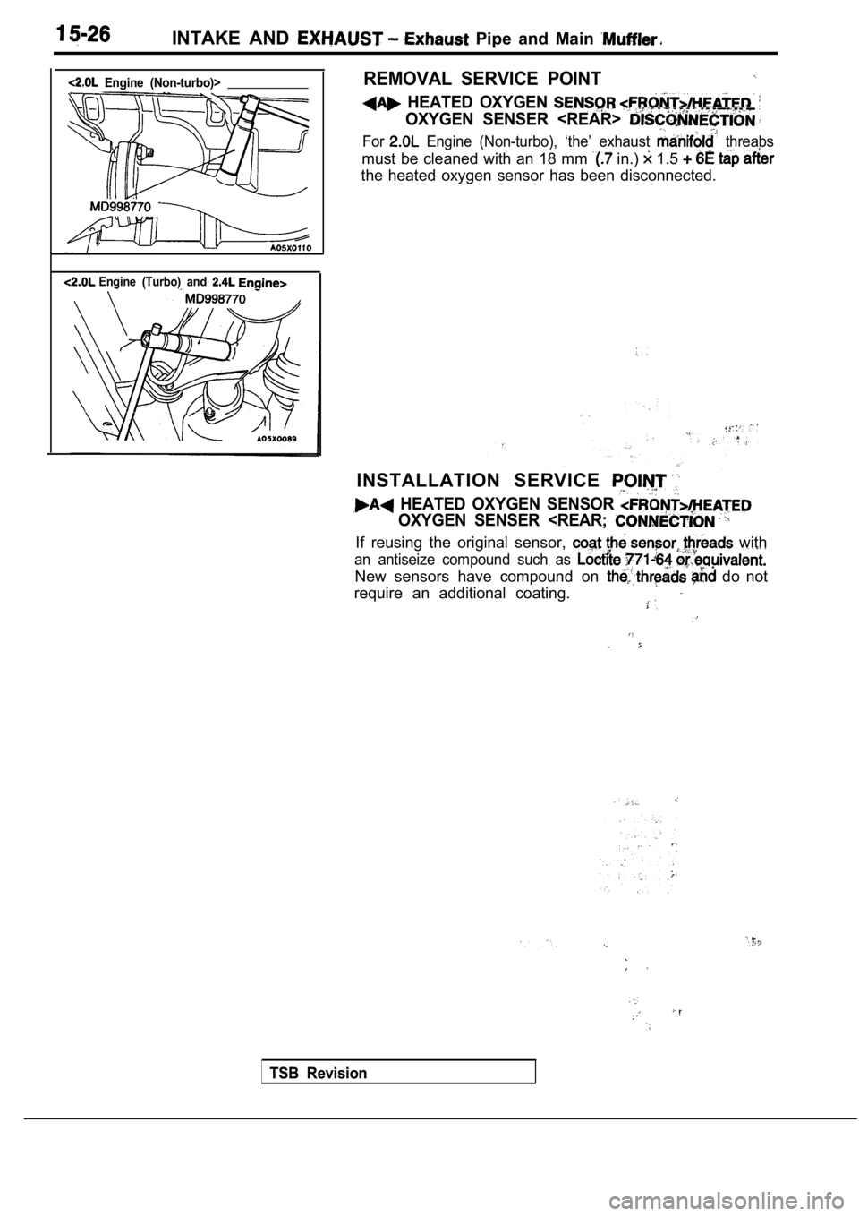
Engine (Non-turbo)>
Engine (Turbo) and
REMOVAL SERVICE POINT
HEATED OXYGEN
OXYGEN SENSER
For Engine (Non-turbo), ‘the’ exhaust threabs
must be cleaned with an 18 mm in.) 1.5
the heated oxygen sensor has been disconnected.
INSTALLATION SERVICE
HEATED OXYGEN SENSOR
OXYGEN SENSER
an antiseize compound such as
New sensors have compound on do not
require an additional coating.
TSB Revision
TSB Revision
Page 741 of 2103

CONTENTS
AUTO-CRUISE CONTROL SYSTEM
. . . . . . . . . . . . . . . . . . . . . . . . . . . . . . . . . . . . .7
AUTO-CRUISE CONTROL* . . . . . . . . . . . . . . 40
GENERAL INFORMATION . . . . . . . . . . . . . . . . 7
ON-VEHICLE SERVICE. . . . . . . . . . . . . . . . . 33
Auto-cruise Control Cable Check and
Adjustment . . . . . . . . . . . . . . . . . . . . . . . . . . . . . .
33
Auto-cruise Control Component Check . . . . . 37
Auto-cruise Control System Operation Check
. . . . . . . . . . . . . . . . . . . . . . . . . . . . . . . . . . . . . . . . .
35
SERVICE SPECIFICATIONS . . . . . . . . . . . . . 8
SPECIAL TOOLS . . . . . . . . . . . . . . . . . . . . . . . . 8
TROUBLESHOOTING
ENGINE (NON-TURBO)> . . . . . . . . . . . 9
TROUBLESHOOTING
(TURBO) AND ENGINE> . . . . .
EMISSION CONTROL’ SYSTEM
. . . . .
CATALYTIC . . . . . . . . . . . . . .
General Information . . . . . . . . . . . . . . . . . . 57
EVAPORATIVE EMISSION .
SYSTEM. . . . . . . . . . . . . . . .
Air Conditioning . . . . . . . . . . . . . . . . . . . 52
Component Location
. . . . . . . . . . . . . . . . . .
Engine Coolant Temperature Sensor
Intake Air Temperature Sensor . . . . . . . . . . . . 52
WARNINGS REGARDING SERVICING OF SUPPLEMENTAL RESTRA INT SYSTEM (SRS) EQUIPPED
WARNING!
(1) Improper serviceor maintenance of any component of the or any SRS-related can to injuryorcleathtoservicepersonnel (from inadvertentfiring the SRS inoperative).
(2) Service or maintenance of any SRS component or SRS-related component must be performed only
MITSUBISHI dealer.
(3) MITSUBISHI dealer personnel must thoroughly rev iew this manual, and especially its GROUP
Restraint System (SRS) and GROUP 00 Maintenance Service, before any service or maintenance of any
componentof the SRS or any SRS-related component.
NOTEJhe includes the following components: warning light, air bag module, clock components (that may have to be removed/installed in connection with or areIndicated in the table of contents by an asterisk
Page 742 of 2103
17-2
Evaporative Emission Canister/Air Filter/
Evaporative Emission Ventilation Solenoid
. . . . . . . . . . . . . . . . . . . . . . . . . . . . . . . . . . . . . . . . .53
Evaporative Emission Purge Solenoid
Check. . . . . . . . . . . . . . . . .. . . . . . . . . . . . . . . . . . .
General Information. . .. . .. . . . . . . . . . . . . . .
Purge Control System Check. . . . . . . . . . . . .
Purge Port Vacuum Check. . . . . . . . . . . . . . . .51
EXHAUST GAS (EGR)
SYSTEM. . . . . . . . . . . . . . . . . . . . . . . . . . . . . . . 54
Component Location. . . . . . . . . . . . . . . . . . . . .54
EGR Port Vacuum Check. . . . . . . . . . . . . . . . .56
EGR System Check. . . . . . . . . . . . . . . . . . . . . .55
EGR Valve Check. . . . . . . . . . . . . . . . . . . . . . . .55
Electric EGR Transducer Solenoid Check
. . . . . . . . . . . . . . . . . . . . . . . . . . . . . . . . . . . . . . . . .
56
General Information. . . . . . . . . . . . . . . . . . . . . .54
GENERAL INFORMATION. . . . . . . . . . . . . . .44
POSITIVE CRANKCASE VENTILATION
SYSTEM. . . . . . . . . . . . . . . . . . . . . . . . . . . . . . . 48
Component Location. . . . . . . . . . . . . . . . . . . . .48
Crankcase Ventilation System Check. . . . . .49
General Information. . . . . . . . . . . . . . . . . . . . . .48
Positive Crankcase Ventilation Valve
Check. . . . . . . . . . . . . . . . . . . . . . . . . . . . . . . . . . .49
SERVICE SPECIFICATIONS. . . . . . . . . . . . .45
TROUBLESHOOTING’
. . . . . . . . . . . . . . . . . . .45
VACUUM HOSES. . . . . . . . . . . . . . . . . . . . . ..4 8
Vacuum Circuit Diagram. . . . . . . . . . . . . . . . . .47
Vacuum Hose Routing
. . . . . . . . . . . . . . . . . . . .46
CONTROL SYSTEM
ENGINE (TURBO) AND
ENGINE>. . . . . . . . . . . . . . . . . . . . . 6 0
CATALYTIC CONVERTER. . . . . . . . . . . . . . .89
General Information. . . . . . . . . . . . . . . . . . . . . .89
EVAPORATIVE EMISSION CONTROL
SYSTEM. . . . . . . . . . . . . . . . . . . . . . . . . . . . . . .69’
Air Conditioning Switch
. . . . . . . . . . . . . . . . . . .77
Component Location Engine (Turbo)>
. . . . . . . . . . . . . . . . . . . . . . . . . . . . . . . . . . . . . . . . .
69
Component Location Engine (Turbo)>
. . . . . . . . . . . . . . . . . . . . . . . . . . . . . . . . . . . . . . . . .
70
Evaporative Emission Canister/Fuel Tank
Pressure Relief Valve/Purge Control Valve
. . . . . . . . . . . . . . . . . . . . . . . . . . . . . . . . . . . . . . . . .78
Evaporative Emission Purge Solenoid
Check. . . . . . . . . . . . . . . . . . . . . . . . . . . . . . . . . . .76
General Information Engine (Turbo)> G e n e r a l I n f o r m a t i o n
. . . . . . . . . . . . . . . . . .
. . . . . . . . . . . . . . . . . . . . . . .70
Purge Control System Check
. . . . . . . . . . . . . . . . . . . . . . . . . .. . . . . . . . . . . . . . . .71
Purge Control ‘System
(Purge Flow Check) Engine>. . . . . . .73
Purge Control Engine (Turbo)>
. . . . . . . . . . . . . . . . . . . . . . . . . . . . . . . . . . . . . . . . . .
Purge Port Vacuum Check. . . . . . . . . . . . . . . .75
Volume Air Flow Sensor, Engine Coolant
Temperature Sensor and Intake Air
Temperature Sensor. . . . . . . . . . . . . . . . . . . . . . .77
RECIRCULATION (EGR)
.... . .. . . . . . . . . . . . . . . . . . . . . . . .81
Component Location. . . . . . . . . . . . . . . . . . . . .82
EGR Port Vacuum Check . . . . . . . . . . . . . . . . .86
EGR Solenoid Check Engine (Turbo)>
. . . . . . . . . . . . . . . . . . . . . . . . . . . . . . . . . . . . . . . . .
87
EGR Solenoid Check Engine>. . . . . .
EGR System Check . . . . . . . . . . . . . . . . . .
EGR Valve Check. . . . . . . . . . . . .. . .
General Information... . . . . . . . . . . . . .....81
Vacuum Control Valve Check
. . . . . . . . .
.......................................
POSITIVE CRANKCASE VENTILATION
SYSTEM
. . . . . . . ... . .. . . . . . . . . . . . . . . . . 65
Component Location. . . . . . . . . . . . .. . . . . . . . .66
Crankcase Ventilation. System . .67
General Information
. . . .. . . . . ... . ........
Positive Crankcase Ventilation Valve
Check. . . . . . . . . . . . . . . . . . . . . ... . ............
SERVICE SPECIFICATIONS. .. . . . . . . . . 60
SPECIAL TOOL . . . . . . . . . . . . . . . . . . . . . . .
. . .. .
HOSES
. . . . ..
. . . . . . . . . . . . . . . . . . . . .,
Circuit Diagram.. . . . . . . . . . . . . . . . . . ,
Vacuum Hose Routing. . . . . . . ...... . . . 6 1
ENGINE CONTROL
3
ACCELERATOR
......
GENERAL INFORMATION . . . . . .. . . . . . . . . .3
ON-VEHICLE SERVICE. . . . . . . . . . . .4
Accelerator Cable Check and
Adjustment. . . . . . . . . . . . . . . . . . . . . . . . . . . . . . .
SERVICE SPECIFICATION. . . . . . . . . . . . . . .3
. ... . . . . ...3. . . . . . . . . . . . . . . . . . . . . . . . . . . . . . . . . . . . . . . . .
69
Page 743 of 2103
ENGINE AND EMISSION CONTROL Engine Control System
GENERAL INFORMATION
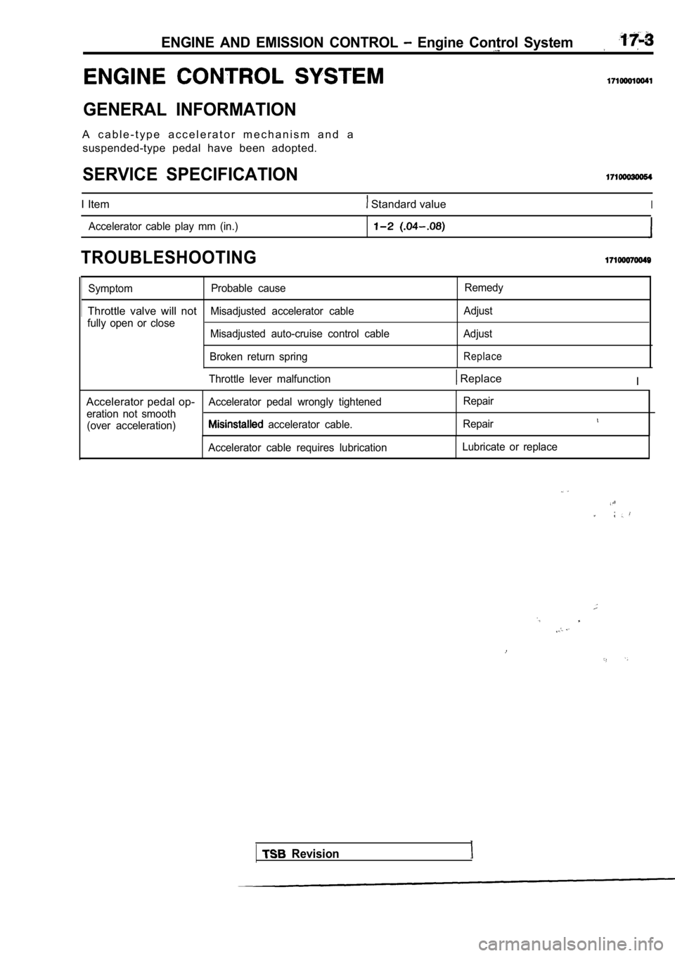
A c a b l e - t y p e a c c e l e r a t o r m e c h a n i s m a n d asuspended-type pedal have been adopted.
SERVICE SPECIFICATION
I Item Standard valueI
Accelerator cable play mm (in.)
TROUBLESHOOTING
Symptom Probable cause Remedy
Throttle valve will notMisadjusted accelerator cable
Adjust
fully open or close Misadjusted auto-cruise control cable Adjust
Broken return spring
Replace
Throttle lever malfunction Replace I
Accelerator pedal op-
Accelerator pedal wrongly tightened Repair
eration not smooth (over acceleration)
accelerator cable. Repair
Accelerator cable requires lubrication Lubricate or replace
Revision
Page 748 of 2103
E N G I N E A N D E M I S S I O N C O N T R O L .
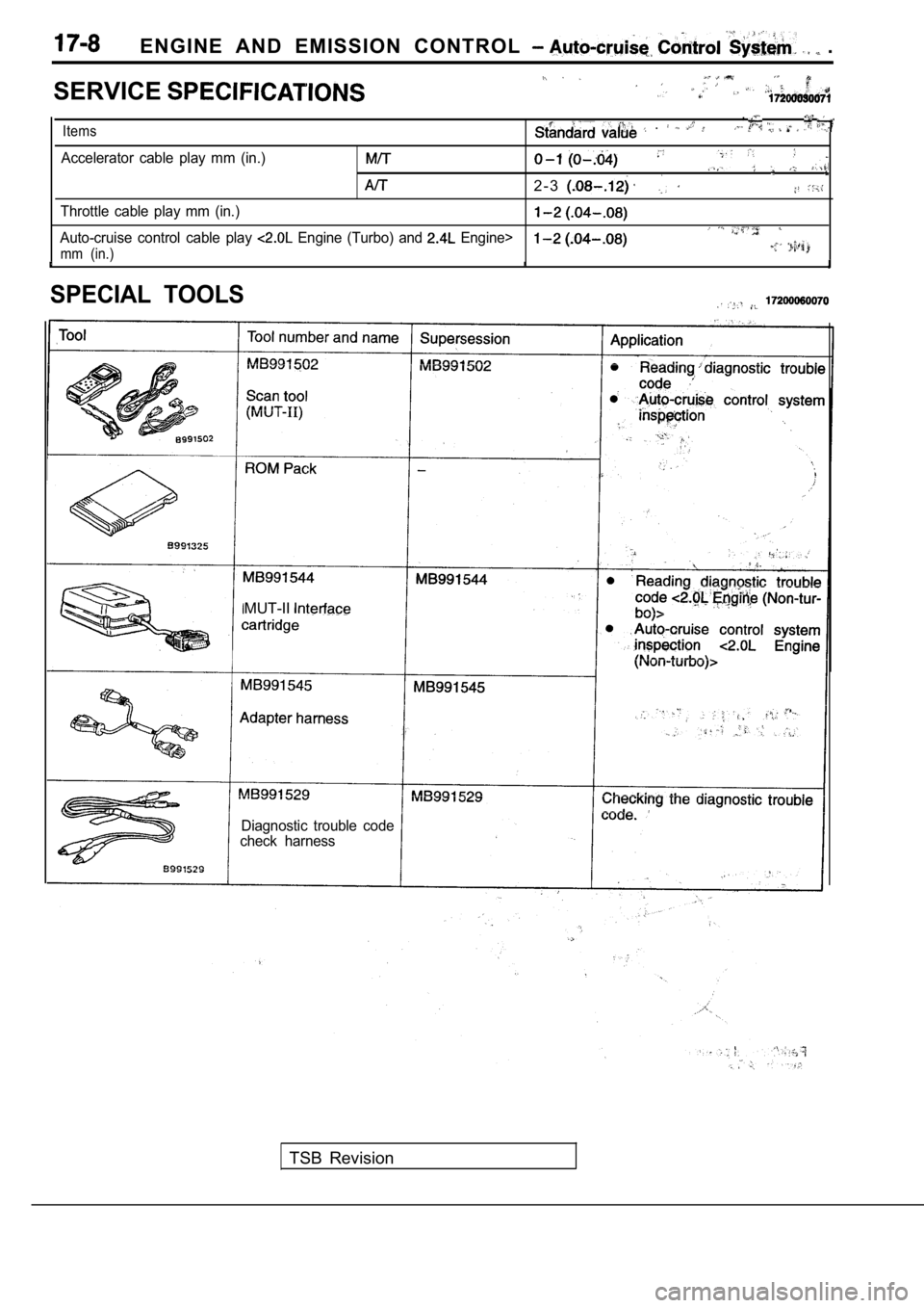
SERVICE
,
Items .
Accelerator cable play mm (in.)
2 - 3
Throttle cable play mm (in.)
Auto-cruise control cable play Engine (Turbo) and Engine>
mm (in.)
SPECIAL TOOLS
MUT-II
Diagnostic trouble code
check harness
TSB Revision
Page 773 of 2103
ENGINE AND EMISSION CONTROL Auto-cruise
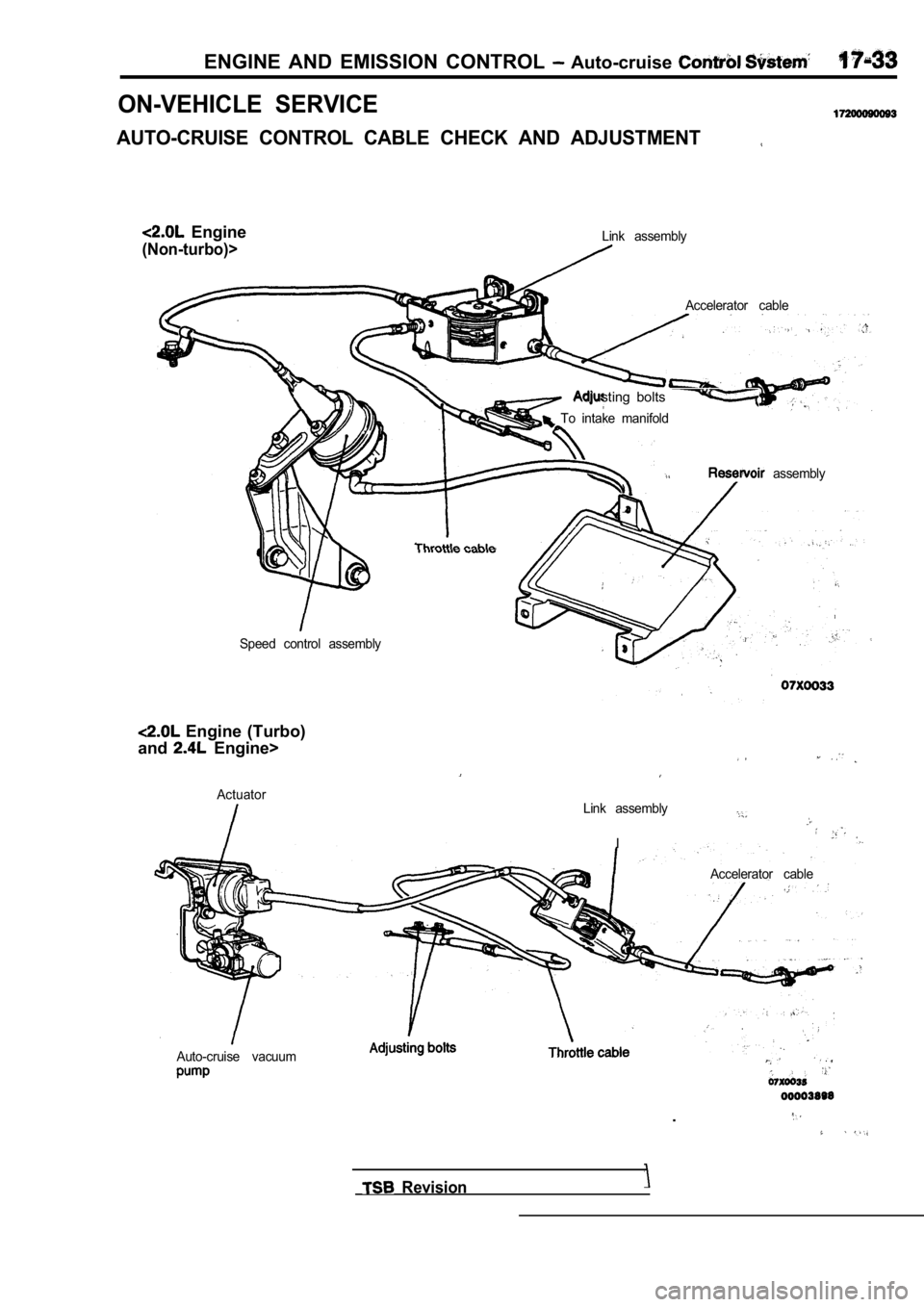
ON-VEHICLE SERVICE
AUTO-CRUISE CONTROL CABLE CHECK AND ADJUSTMENT
Engine
(Non-turbo)>Link assemblyAccelerator cable
Adjusting bolts
To intake manifold
assembly
Speed control assembly
Engine (Turbo)
and
Engine>
ActuatorLink assembly
I
Accelerator cable
Auto-cruise vacuum
.
Revision
Page 782 of 2103
17-42ENGINE AND EMISSION CONTROL Auto-cruise Control System
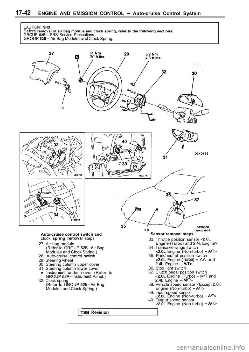
CAUTION:Beforeremoval of air bag module and clock spring, refer t o the following sections:GROUP SRS Service Precautions.GROUP Air Bag Modules Clock Spring.
5.9 Nm4.3
41Nm30
2 8
Auto-cruise control switch and
clock spring
steps
27. Air bag module (Refer to GROUP
Bag
Modules and Clock Spring.)
28. Auto-cruise control
29. Steering wheel
30. Steering column upper cover
31. Steering column lower cover
l
under cover (Refer to
GROUP Panel.)
32. Clock spring (Refer to GROUP
Bag
Modules and Clock Spring.) 3 8
Sensor removal steps
33. Throttle position sensor
Engine (Turbo) and Engine>
34. Transaxle range switch
Engine (Non-turbo) 35. Park/neutral position switch Engine AA and Engine
36. Stop light switch
37. Clutch pedal position switch
Engine (Turbo) M/T and Engine 38. Vehicle speed sensor