Page 721 of 2103
INTAKE AND EXHAUST Intake Manifold Engine
REMOVAL AND INSTALLATION
Operationl Residual Fuel Pressure Releasing(Refer to GROUP Service.)l Engine Coolant Draining(Refer to GROUP Service.)l Reservoir Assembly Removal with Auto-Cruise
2.9
Post-installation Operationl Reservoir Assembly Installation
l Engine Coolant Supplying (Refer to GROUP Service.)l Accelerator Cable Adjustment (Refer to GROUP 17 On-vehicle Service.)
3.92 . 9
O-ring
Engineoil
Removalsteps
1. Air intake hose2.Breather hose
3. Accelerator cable connection
4. Clip5. MAP sensor connector
6. Charge temperature sensor connector
7. Vacuum hose connection
8.TPS connector9. motor connector 10.
wiring harness11. connection
12. PCV hose assembly 13. Vacuum hose connection14. Brake booster hose
connection
15. pipe connection
16. fuel hose connection
TSB Revision
Page 723 of 2103
INTAKE AND EXHAUST Intake Manifold Engine ,
Fuel rail, fuel injectorand pressureregulator
O-ring
REMOVAL SERVICE POINTS
HIGH-PRESSURE FUEL HOSE DISCONNECTION
Relieve pressure in the fuel pipe line to prevent f uel outflow.
(Refer to GROUP On-vehicle Service.)
Caution
Cover fuel pipe line with shop towel after relievin g pres-
sure as certain pressure may still remain.
RAIL, FUEL INJECTOR AND PRESSURE
REGULATOR ASSEMBLY REMOVAL
Remove fuel rail with fuel injector and pressure re gulator
on.
Caution
Do not drop fuel injector when removing fuel rail.
INSTALLATION SERVICE POINTS
RAIL, FUEL INJECTOR AND PRESSURE
REGULATOR ASSEMBLY INSTALLATION
Apply a small amount of new engine oil to the O-rin g.
HIGH-PRESSURE FUEL HOSE CONNECTION
When connecting the high-pressure fuel hose to the fuel rail,
apply a small amount of new engine oil to the hose union,
and then insert, being careful not to damage the O- ring.
Caution
Do not let engine oil get into the fuel rail.
TSB Revision
Page 725 of 2103

INTAKE AND EXHAUST Intake Manifold Engine
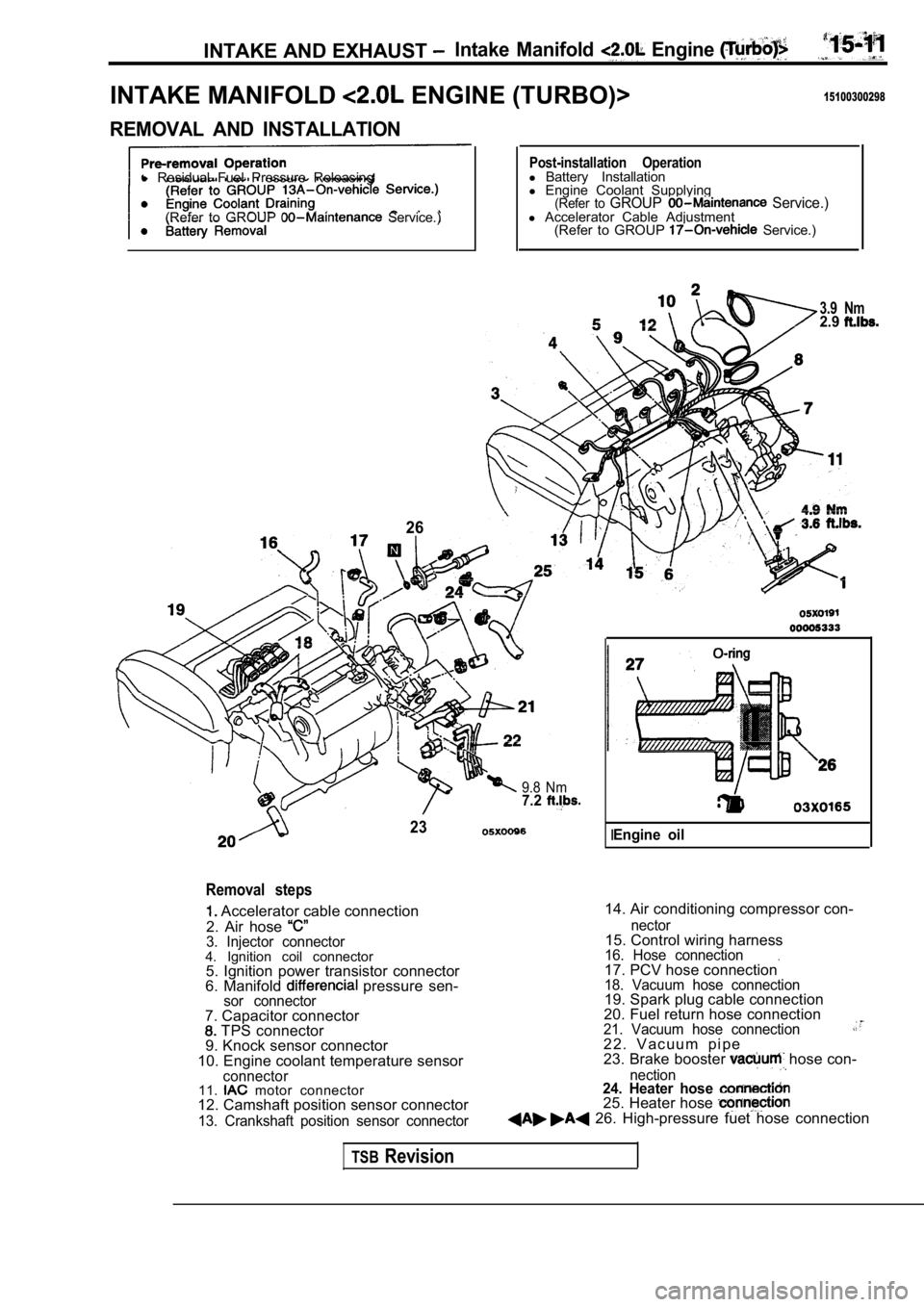
INTAKE MANIFOLD ENGINE (TURBO)>15100300298
REMOVAL AND INSTALLATION
l Residual Fuel Pressure Releasing
(Refer to GROUP
Service.)
26
Post-installation Operationl Battery Installation
l Engine Coolant Supplying
(Refer to GROUP Service.)l Accelerator Cable Adjustment
(Refer to GROUP Service.)
3.9 Nm2.9
9.8 Nm7.2
23
Removal steps
Accelerator cable connection
2. Air hose
3. Injector connector4. Ignition coil connector 5. Ignition power transistor connector
6. Manifold
pressure sen-sor connector
14. Air conditioning compressor con-
7. Capacitor connector
TPS connector
9. Knock sensor connector
10. Engine coolant temperature sensor
connector11. motor connector
12. Camshaft position sensor connector
13. Crankshaft position sensor connector nector
15. Control wiring harness16. Hose connection.17. PCV hose connection18. Vacuum hose connection19. Spark plug cable connection
20. Fuel return hose connection
21. Vacuum hose connection2 2 . V a c u u m p i p e
23. Brake booster hose con-
nection24. Heater hose 25. Heater hose 26. High-pressure fuet hose connection
IEngine oil
TSBRevision
Page 727 of 2103

AND EXHAUST Intake Manifold
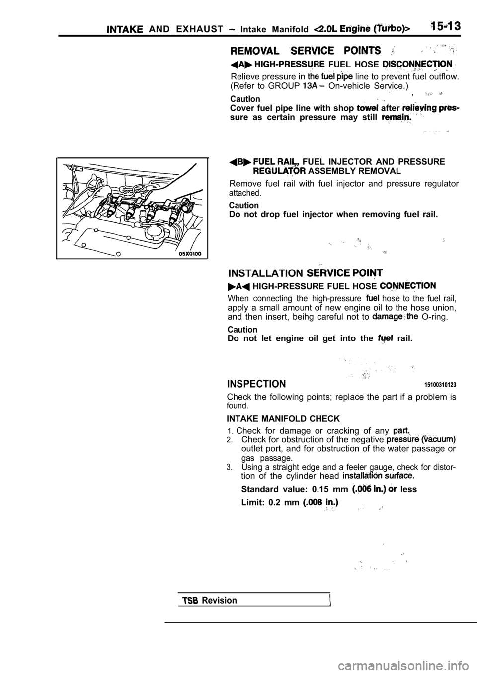
FUEL HOSE
Relieve pressure in line to prevent fuel outflow.
(Refer to GROUP
On-vehicle Service.)
Cautlon,
Cover fuel pipe line with shop after
sure as certain pressure may still
FUEL INJECTOR AND PRESSURE
ASSEMBLY REMOVAL
Remove fuel rail with fuel injector and pressure re gulator
attached.
Caution
Do not drop fuel injector when removing fuel rail.
INSTALLATION
HIGH-PRESSURE FUEL HOSE
When connecting the high-pressure hose to the fuel rail,
apply a small amount of new engine oil to the hose union,
and then insert, beihg careful not to
O-ring.
Caution
Do not let engine oil get into the rail.
INSPECTION15100310123
Check the following points; replace the part if a p roblem is
found.
INTAKE MANIFOLD CHECK
1. Check for damage or cracking of any
2.Check for obstruction of the negative
outlet port, and for obstruction of the water passa ge or
gas passage.
3.Using a straight edge and a feeler gauge, check for distor-
tion of the cylinder head
Standard value: 0.15 mm less
Limit: 0.2 mm
Revision
Page 728 of 2103

INTAKE AND EXHAUST Intake Manifold
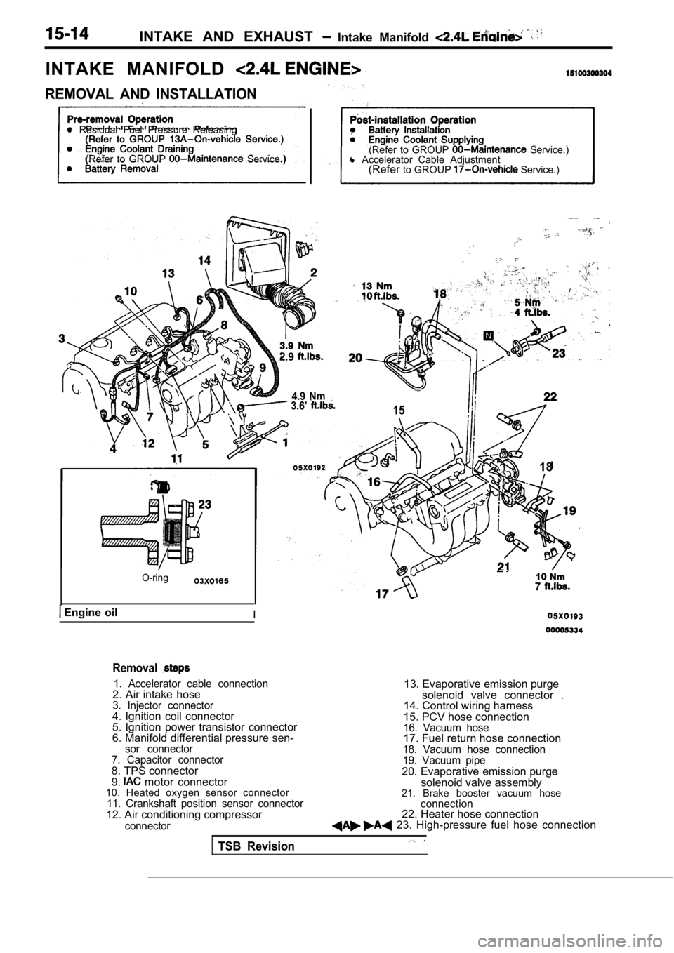
INTAKE MANIFOLD
REMOVAL AND INSTALLATION
l Residual Fuel Pressure Releasing
(Refer to GROUP
Service.) (Refer to GROUP Service.)
l Accelerator Cable Adjustment
(Refer to GROUP
Service.)
2.9
4.9 Nm 3.6’ 15
O-ring
Engine oilI
18
10 Nm7
Removal
1. Accelerator cable connection2. Air intake hose3. Injector connector4. Ignition coil connector
5. Ignition power transistor connector
6. Manifold differential pressure sen-
sor connector
7. Capacitor connector
8. TPS connector
9. motor connector
10. Heated oxygen sensor connector
11. Crankshaft position sensor connector12. Air conditioning compressor
connector
13. Evaporative emission purge
solenoid valve connector .
14. Control wiring harness
15. PCV hose connection
16. Vacuum hose17. Fuel return hose connection18. Vacuum hose connection
19. Vacuum pipe
20. Evaporative emission purge solenoid valve assembly
21. Brake booster vacuum hose
connection22. Heater hose connection 23. High-pressure fuel hose connection
TSB Revision
Page 730 of 2103

INTAKE AND EXHAUST Intake Manifold
REMOVAL SERVICE POINTS
HIGH-PRESSURE FUEL HOSE DISCONNECTION
Relieve pressure in the fuel pipe line to prevent fuel outflow.
(Refer to GROUP On-vehicle Service.)
Caution
Cover fuel pipe line with shop towel after relievin g pres-
sure as certain pressure may
remain.
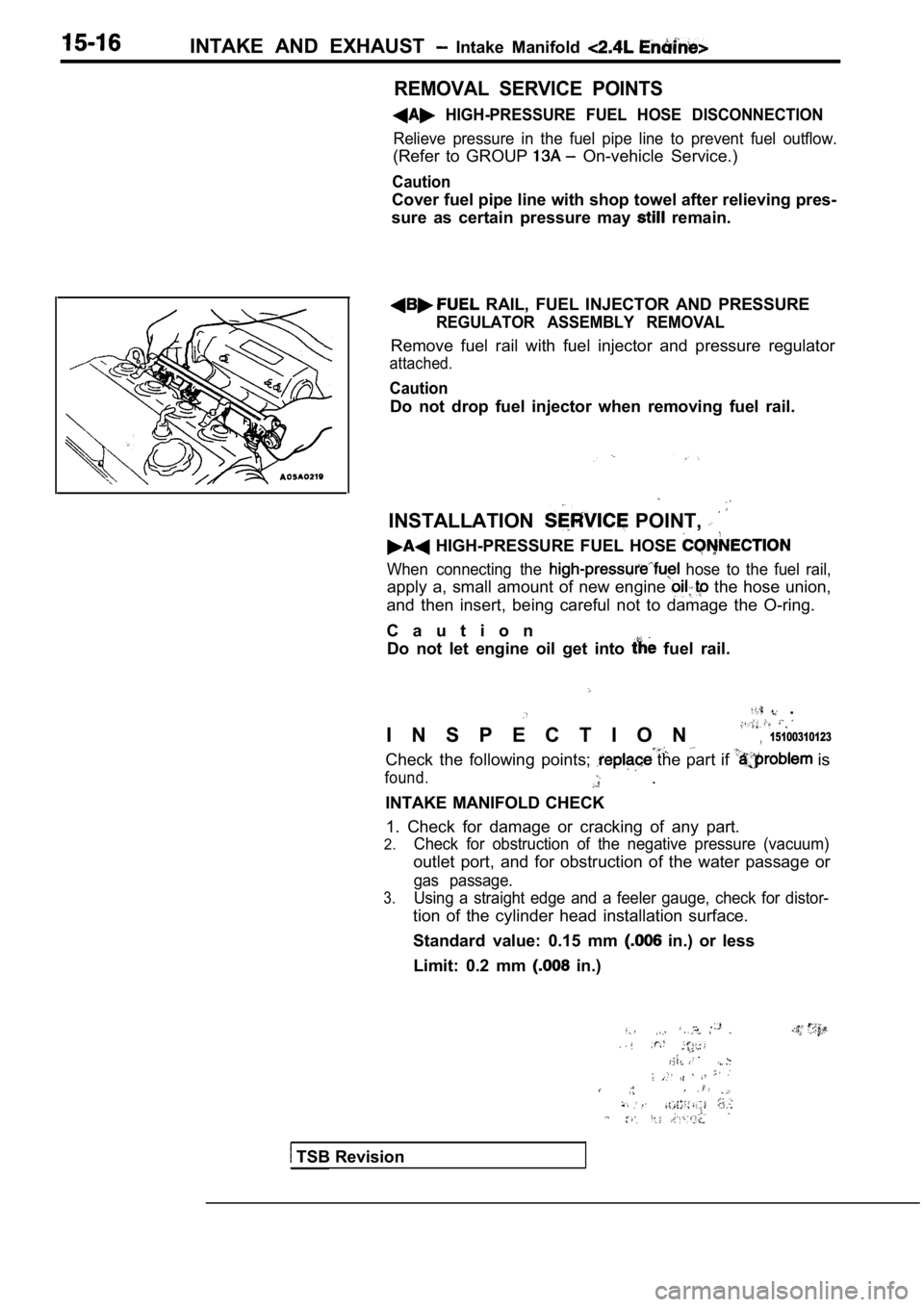
RAIL, FUEL INJECTOR AND PRESSURE
REGULATOR ASSEMBLY REMOVAL
Remove fuel rail with fuel injector and pressure re gulator
attached.
Caution
Do not drop fuel injector when removing fuel rail.
INSTALLATION POINT,
HIGH-PRESSURE FUEL HOSE
When connecting the hose to the fuel rail,
apply a, small amount of new engine the hose union,
and then insert, being careful not to damage the O- ring.
C a u t i o n Do not let engine oil get into
fuel rail.
.
I N S P E C T I O N 15100310123
Check the following points; the part if is
found. .
INTAKE MANIFOLD CHECK 1. Check for damage or cracking of any part.
2.Check for obstruction of the negative pressure (vac uum)
outlet port, and for obstruction of the water passage or
gas passage.
3.Using a straight edge and a feeler gauge, check for distor-
tion of the cylinder head installation surface.
Standard value: 0.15 mm
in.) or less
Limit: 0.2 mm
in.)
TSB Revision
Page 732 of 2103
INTAKE AND EXHAUST Exhaust Manifold
E X H A U S T M A N I F O L D E N G I N E ( T U R B O ) >
REMOVAL AND INSTALLATION
Pre-removal and Post-installation OperationEngine Coolant Draining and Refilling
l Engine Oil Draining and Refilling
(Refer to GROUP 00
Maintenance Service.)
Nm
12-15 Nm8.8-11- - 1 6 ’
3
. .
Removal steps
1. Condenser fan motor assembly with air conditioning>
2. Heated oxygen sensor
3. Engine oil level gauge guide
4. Air cleaner and air intake hose
assembly5. Air hose (A) connection
6. Water hose connection
7. Water hose connection
8. Oil pipe (A) connection 9. Heat protector
A)
10. Heat protectorB)
11. Engine hanger
12. Front exhaust pipe connection 13. Flange bolts 14. Flange 15.
Coned disc spring .16. Exhaust -manifold17.Exhaust manifold gasket Ring19. Gasket (A)
TSB Revision
Page 733 of 2103
INTAKE AND EXHAUST Exhaust Manifold
24 ,
54-64 Nm
20. Vacuum hose assembly 21. Turbocharger assembly22. Oil return pipe
23. Water pipe assembly (B) 24. Oil pipe 25. Water pipe assembly (A)
26. manifold fitting27.Ghsket
REMOVAL SERVICE
HEATED OXYGEN SENSOR REMOVAL
TSB Revision
TURBOCHARGER ASSEMBLY
Remove the turbocharger
assembly with the exhaust fitting,
water pipe assembly (A), water pipe assembly (B) an d the
oil pipe assembly attached to it.
OIL PIPE ASSEMBLY REMOVAL
Caution
After disconnecting the oil pipe, take care that fo reign
materialdoesnotenter the oil passage hole of the turbo-
charger assembly.