Page 643 of 2103

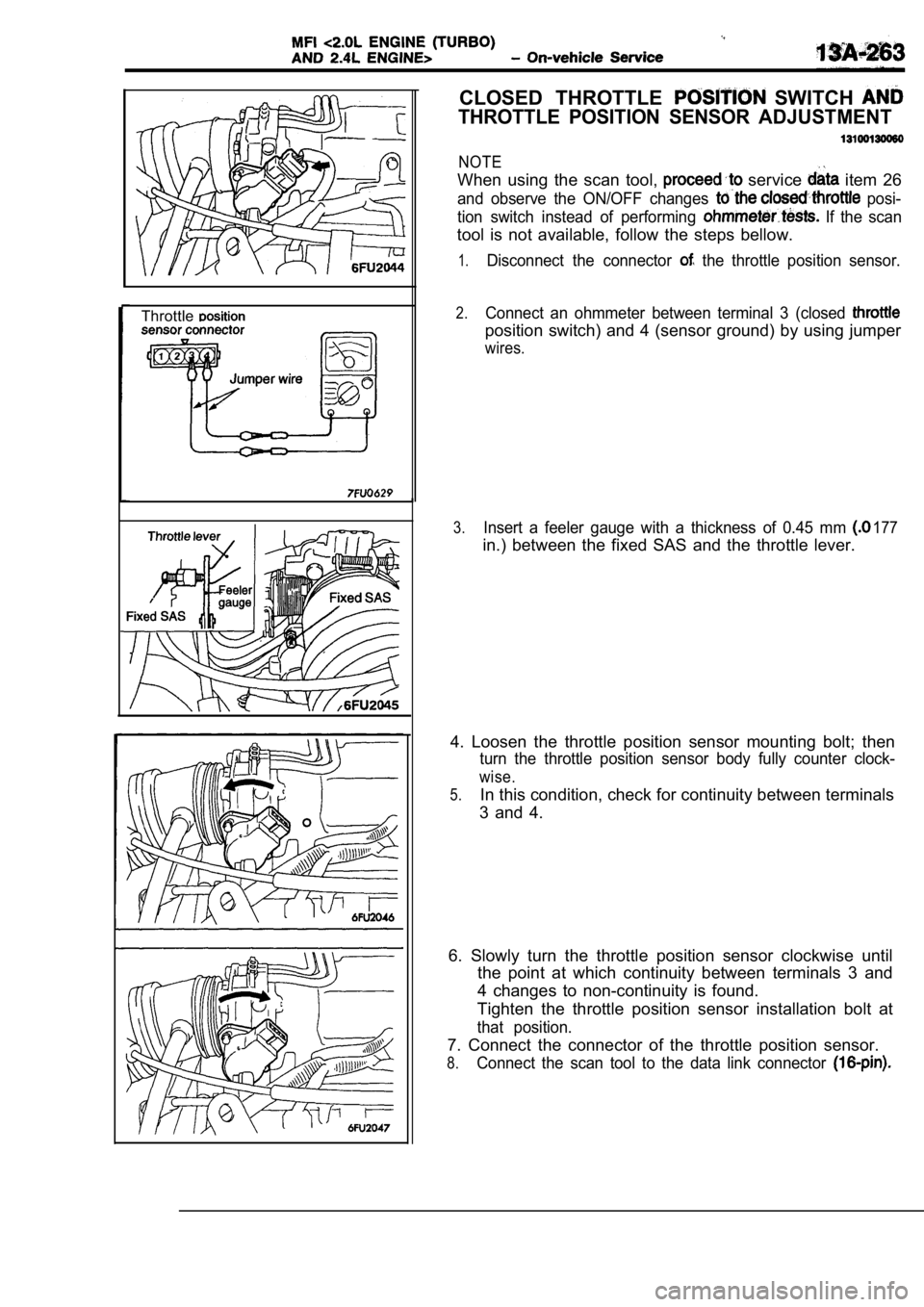
Throttle
CLOSED THROTTLE SWITCH
THROTTLE POSITION SENSOR ADJUSTMENT
NOTE
When using the scan tool, service item 26
and observe the ON/OFF changes posi-
tion switch instead of performing
If the scan
tool is not available, follow the steps bellow.
1.Disconnect the connector the throttle position sensor.
2.Connect an ohmmeter between terminal 3 (closed
position switch) and 4 (sensor ground) by using jum per
wires.
177
3.Insert a feeler gauge with a thickness of 0.45 mm
in.) between the fixed SAS and the throttle lever.
4. Loosen the throttle position sensor mounting bol t; then
turn the throttle position sensor body fully counter clock-
wise.
5.In this condition, check for continuity between terminals
3 and 4.
6. Slowly turn the throttle position sensor clockwi se until
the point at which continuity between terminals 3 a nd
4 changes to non-continuity is found.
Tighten the throttle position sensor installation b olt at
that position.
7. Connect the connector of the throttle position s ensor.
8.Connect the scan tool to the data link connector
Page 668 of 2103
Connect a hand vacuum pump to the nipple.
Connect a battery to the solenoid valve and apply a vacu-
um to check air-tightness.
Battery voltage
Not applied
Applied nipple
Open
Closed
Open Normal condition
Vacuum leaks
Vacuum maintained
Vacuum maintained
Measure the resistance between the terminals of the sole-
noid valve.
Standard value: 36-44
[at
3.
4.
5.
EVAPORATIVE EMISSION PURGE SOLENOID
CHECK
Refer to GROUP 17 Emission Control System.
EGR SOLENOID CHECK13100570152
Refer to GROUP 17 Emission control System. Engine
(Turbo)>
Refer to GROUP 17 Emission Control System.
Engine>
WASTE GATE SOLENOID
Refer to GROUP 15 On-vehicle Service.
Page 670 of 2103

( T U R B O )
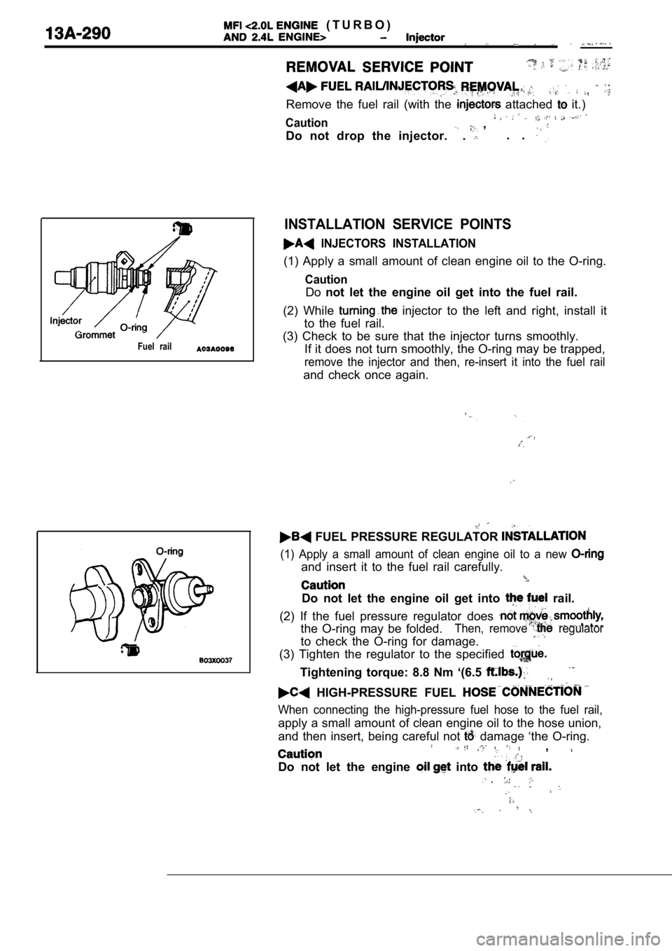
Remove the fuel rail (with the attached it.)
Caution ,
Do not drop the injector.
. . .
Fuel rail
INSTALLATION SERVICE POINTS
INJECTORS INSTALLATION
(1) Apply a small amount of clean engine oil to the O-ring.
Caution
Donot let the engine oil get into the fuel rail.
(2) While
injector to the left and right, install it
to the fuel rail.
(3) Check to be sure that the injector turns smooth ly.
If it does not turn smoothly, the O-ring may be tra pped,
remove the injector and then, re-insert it into the fuel rail
and check once again.
FUEL PRESSURE REGULATOR
(1) Apply a small amount of clean engine oil to a n ew
and insert it to the fuel rail carefully.
Do not let the engine oil get into rail.
(2) If the fuel pressure regulator does
the O-ring may be folded.Then, remove regulator
to check the O-ring for damage.
(3) Tighten the regulator to the specified
Tightening torque: 8.8 Nm ‘(6.5
HIGH-PRESSURE FUEL
When connecting the high-pressure fuel hose to the fuel rail,
apply a small amount of clean engine oil to the hose union,
and then insert, being careful not
damage ‘the O-ring.,
Do not let the engine into
,
Page 671 of 2103
E N G I N E ( T U R B O )
AND ENGINE>
REMOVAL AND INSTALLATION
(Refer to 17 Service.)
Engine (Turbo)>
2 A . .
4.93.6
Removal steps
1. Accelerator cable connection2. Air hose Engine (Turbo)>3. Air intake hose Engine>4. TPS connector
5. motor connector
6. Vacuum hose connection 7. Heater hose connection
8. Charge air
cooler fitting Engine Gasket Engine10. Throttle body 11. Throttle body gasket
INSTALLATION SERVICE POINT.
BODY GASKET INSTALLATION
Install the throttle body gasket so that the projec tion is where
shown in the illustration.
Caution
Poor idling etc. may result if the throttle body ga sket
is installed incorrectly.
Page 673 of 2103
1.4
steps
1. Throttle position sensor (with in closed throttle position switch)2. Idle air control motor
3. Gasket
4. Throttle body
DISASSEMBLY SERVICE POINTS
POSITION SENSOR AND IDLE All?
CONTROL MOTOR REMOVAL
1. Do not disassemble the sensor and motor.
2.Do not immerse solvent to clean the sensor and moto r.
Clean then with shop towel.
REMOVAL
1. Do not remove the throttle valve.
2. Check if the vacuum port or passage is clogged. Use
compressed air to clean the vacuum passage.
REASSEMBLY SERVICE POINT
THROTTLE POSITION SENSOR INSTALLATION
Install the throttle position sensor to the thrott le body
as shown in the diagram.
Throttle position sensor
Page 677 of 2103
, ,
CONTENTS
FUEL FILTER . . . . . . . . . . . . . . . . . . . . . . 12SERVICE . . . . .
FUEL TANK. . . . . . . . . . . . . . . . . . . . . . . . 2SPECIAL TOOL. . . . . . . . . , . . . . . , . . . . . . ‘2
FUEL TANK4. . . . . . . . . . . . . . . . . . . . .3. . . . . . . . . . . . . . . . . . . . . . . . . . . . .
GENERAL INFORMATION . . . . . . . . . . . . . . . . 2
Page 680 of 2103
FUEL SUPPLY Tank
FUEL TANK
REMOVAL AND INSTALLATION
Engine (Non-turbo)>34
2.5 Nm
251.8
2.5 Nm
Removal steps
1. Fuel tank
2. High-pressure fuel hose
3. Return hose
4. Fuel pump assembly
5. Fuel gauge unit
6. Fuel cut-off valve assembly
7. Vapor hose
8. Fuel tank filler tube cap9. Filler hose10. Vapor hose
TSB Revision
11. Fuel tank filler tube protector12. Reinforcement13. Fuel tank filler tube assembly14. Packing
NOTE
When replacing the fuel pump assembly or the fuel g auge
unit only, it is possible to work from the service halesunderneath the rear seat cushion without having toremove the fuel tank. (Refer to
Page 681 of 2103
SUPPLY ‘Fuel Tank
Enaine
(Refer to GROUP On-vehicle Service.)
2.5 Nm1.8
Removal steps
1. Fuel tank
2. Vapor hose
3. High-pressure fuel hose
4. Return hose
, ,
12. Fuel tank filler protector
14. Fuel tank’ assembly Packing
5. Fuel pump 6. Fuel gauge unit
7. Fuel cut-off valve assembly
6. Vapor hose
.
NOTE
When replacing the fuel or the gaugeunit only, it is possible to work from the holesunderneath the rear seat without having to
TSB Revision