Page 708 of 2103
ENGINE COOLING Water Pump Engine (Turbo) and.
WATER PUMP ENGINE (TURBO) AND 1 4 1 0 0 2 7 0 1 5 5 ,
REMOVAL AND INSTALLATION
Pm-removal and Post-installation lEngine Coolant Draining and Supplying (Refer to
GROUP 00 Maintenance Service.)lFor Timinig Belt Removal and Installation,
Refer to the Following
GROUP Timing Belt.
GROUP Timing Belt.
,
12-15
TSB Revision
12-15
2417
12-15
Removal steps
1.Generator brace2.Waterpump
3. Water pump gasket4.O-ring
Page 710 of 2103
Water: Hose and Water Pipe EngineE N G I N E C O O L I N G ( N o n - t u r b o ) >
WATER HOSE AND WATER PIPE
~ 4 1 0 0 5 5 0 1 1 5
REMOVAL AND INSTALLATION
Pre-removal and Post-installation OperationlEngine Coolant Draining and Supplying (Refer toGROUP 00 Service.)lUnder Cover Removal and Installation (Refer to
GROUP 42 Under Cover.)I I
3.92.9
7
33
Removal steps
1. Air intake hose
2. Air hose connection 7. Radiator fan motor assembly
8. Radiator lower hose connection
3. Control wiring harness connection
4. Water pipe assembly
5. Water hose6. Heater hose connection
9. Water hose10. Front exhaust pipe connection Water inlet pipe assembly 12. O-ring
TSB Revision
Page 712 of 2103
Water Hose and
ENGINE COOLING and Engine>
WATER HOSE AND WATER PIPE
ENGINE (TURBO) AND ENGINE>1 4 1 0 0 3 3 0 2 4 5
REMOVAL AND INSTALLATION
Engine (Turbo)>
Pre-removal and Post-installation Operationl
Engine Coolant Draining and Supplying (Refer to
GROUP 00 Maintenance Service.)
l Air Hose (C) Removal and Installation (Refer to
GROUP 15
Charge Air Cooler.)
l Turbocharger Removal and Installation (Refer toGROUP 15 Exhaust Manifold.)
11
2417
24 Nm17
48Nm35
3
Specified Sealant:
or equivalent
58
Removal steps
1. Radiator upper hose connection
2. Radiator lower hose connection
3. Water hose4. Heater hose connection
5. Water hose
6. Thermostat case assembly
8. Water pipe assembly
9. Water hose
10. Water hose
11. Heater hose connection
12. inlet pipe assembly
hose
Water hose16. Water pipe assembly (A)17. Water pipe assembly (B)
18. Water
19. Water pipe (C)20. Joint
TSB Revision
Page 713 of 2103
Water Hose and Water Pipe
ENGINE COOLING and Engine>
Engine>
Pre-removal and Post-installation Operation“(1) Engine Coolant Draining and Supplying (Refer toGROUP 00 Maintenance Service.)(2) Air Cleaner Removal and Installation
(3) Exhaust Manifold Removal and
(Refer to GROUP 15 Exhaust Manifold.)
Specified Sealant:Mitsubishi Genuine Part No. or equivalent
Removal steps
1. Radiator upper hose connection 2. Radiator lower hose 3. Thermostat case assembly 4. O-ring
5. Water hose 6. Water hose
7. Heater hose connection
8. Water inlet pipe assembly 9. o-ring
TSB Revision
Page 714 of 2103

Water Hose and Water Engine (Turbo)
ENGINE and Engine>
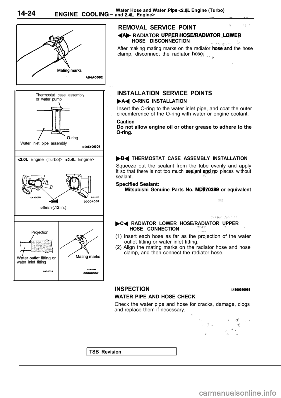
Thermostat case assembly or water pump
O-ring
Water inlet pipe assembly
Engine (Turbo)> Engine>
in.)
Projection
Water fitting orwater inlet fitting
REMOVAL SERVICE POINT
RADIATOR
HOSE DISCONNECTION,After making mating marks on the radiator the hose
clamp, disconnect the radiator
INSTALLATION SERVICE POINTS
O-RING INSTALLATION
Insert the O-ring to the water inlet pipe, and coat the outer
circumference of the O-ring with water or engine co olant.
Caution
Do not allow engine oil or other grease to adhere t o the
O-ring.
THERMOSTAT CASE ASSEMBLY INSTALLATION
Squeeze out the sealant from the tube evenly and ap ply
it so that there is not too much places without
sealant.
Specified Sealant:
Mitsubishi Genuine Parts No. or equivalent
RADIATOR LOWER HOSE/RADIATOR UPPER
HOSE CONNECTION
(1) Insert each hose as far as the projection of th e water
outlet fitting or water inlet fitting.
(2) Align the mating marks on the radiator hose and hose
clamp, and then connect the radiator hose.
INSPECTION
WATER PIPE AND HOSE CHECK
Check the water pipe and hose for cracks, damage, c logs
and replace them if necessary.
TSB Revision
Page 715 of 2103

INTAKE
EXHAUST,
CHARGE AIR COOLER . . . . . . . . . . . . . . . . . . . .6
EXHAUST MANIFOLD
ENGINE (NON-TURBO)> . . . . . . . . . .17
ENGINE (TURBO)> . . . . . . . . . . . . . . .16
ENGINE> . . . . . . . . . . . . . . . . . . . . . . . .21
EXHAUST PIPE AND MAIN MUFFLER . . . . .22
GENERAL INFORMATION. . . . . . . . . . . . . . . . . .2
INTAKE MANIFOLD
ENGINE (NON-TURBO)> . . . . . . . . . . . 7
ENGINE (TURBO)>. . . . . . . . . . . . . . .11
ENGINE>. . . . . . . . . . . . . . . . . . . . . . . .14
ON-VEHICLE SERVICE. . . . . . . . . . . . . . . . . . . . .3
C O N T E N T S1 5 1 6 6 6 6 6 6 7 6
Intake Charge Pressure Control System
Check . . . . . . . . . . , . . . . . . . . . . . . .4
Intake Manifold Vacuum Check. . . . . . . . . . . . . . .
Turbocharger Bypass Valve Check . . . . .
. . . . . . . . . . . . . . . . . . 5
Turbocharger Waste Gate Solenoid Check
< T u r b o > . . . . . . . . . . . . . . . . . . . . . . . . . . . . . . . , . . + . 4
Turbocharger Supercharging Pressure Check
< T u r b o > . . . . . . . . . . . . . . . . . . . . . . . . . . . . . . . . . . . . . 3
SERVICE SPECIFICATIONS . . . . . . . . . . . . . . . . . 2
.
SPECIAL TOOLS . . . . . . ‘ . . . . . . . . . . . . . . . . . . . .2
TROUBLESHOOTING . . . . . . . . . . . . . . . . . . . . . . . 2
.
Page 716 of 2103

General Information/Service Specifications/
INTAKE AND EXHAUST Special Tools/Troubleshooting
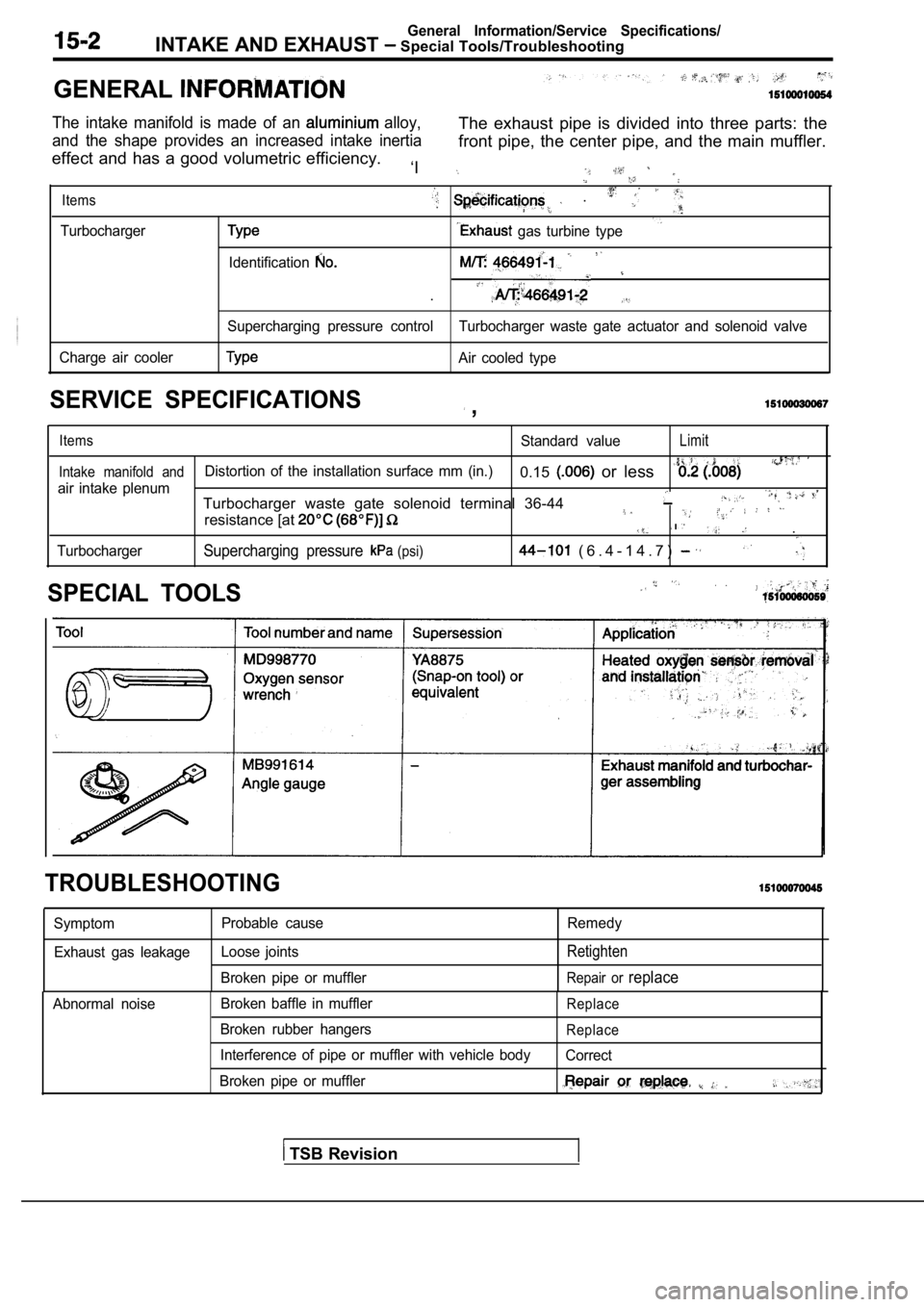
GENERAL
The intake manifold is made of an alloy,
and the shape provides an increased intake inertiaThe exhaust pipe is divided into three parts: the
effect and has a good volumetric efficiency. front pipe, the center pipe, and the main muffler.
‘I
Items .
Turbocharger gas turbine type
Identification
.
Supercharging pressure control Turbocharger waste ga te actuator and solenoid valve
Charge air cooler
Air cooled type
SERVICE SPECIFICATIONS ,
ItemsStandard valueLimit
Intake manifold andDistortion of the installation surface mm (in.)0.15 or less
air intake plenum
TurbochargerTurbocharger waste gate solenoid terminal 36-44
resistance [at .
Supercharging pressure (psi) ( 6 . 4 - 1 4 . 7 )
SPECIAL TOOLS
TROUBLESHOOTING
Symptom Exhaust gas leakage Probable cause
Loose joints
Broken pipe or muffler Remedy
Retighten
Repair or replace
Abnormal noise
Broken baffle in muffler
Broken rubber hangers
Interference of pipe or muffler with vehicle body
Broken pipe or mufflerReplace
Replace
Correct
TSB Revision
Page 717 of 2103

INTAKE AND EXHAUST Service
ON-VEHICLE SERVICE
INTAKE MANIFOLD VACUUM . Engine (Turbo)>
Refer to GROUP 11 A On-vehicle
Engine (Non-turbo)>
Refer to GROUP 11 On-vehicle Service.
Engine>’
Refer to GROUP 11 On-vehicle Service.
TURBOCHARGER SUPERCHARGINGPRESSURE CHECK
Caution
Do a test drive with two passengers in the and
where full throttle acceleration can be safely made .
A driver should not read the pressure gauge, but a front
passenger should.
TSB Revision
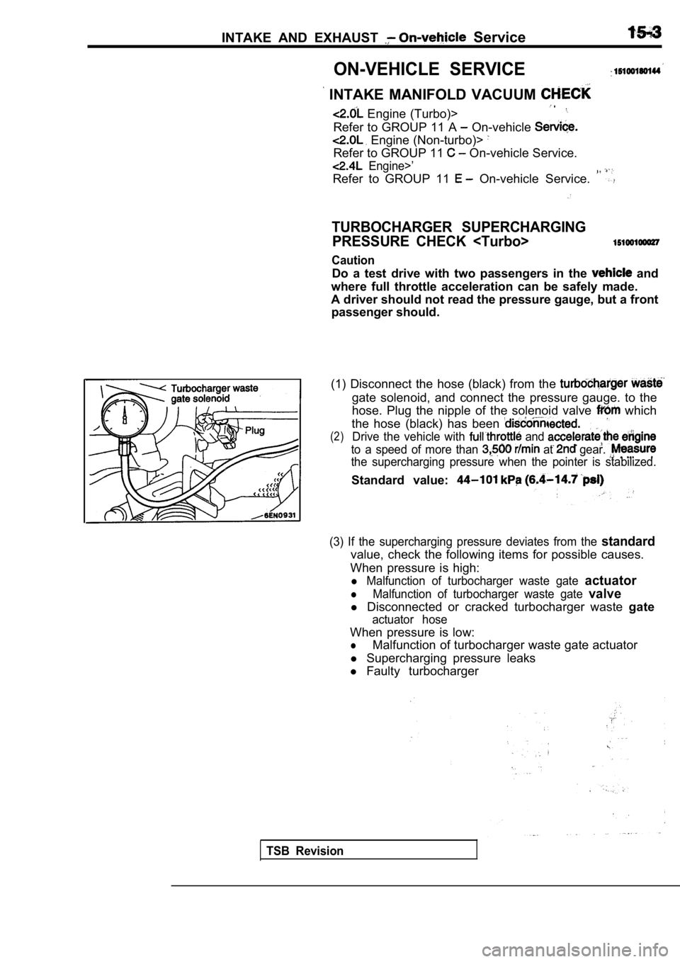
(1) Disconnect the hose (black) from the
gate solenoid, and connect the pressure gauge. to t he
hose. Plug the nipple of the solenoid valve
which
the hose (black) has been
(2)Drive the vehicle with and
to a speed of more than at gear.
the supercharging pressure when the pointer is stab ilized.
Standard value:
(3) If the supercharging pressure deviates from the standard
value, check the following items for possible cause s.
When pressure is high:
l Malfunction of turbocharger waste gate actuator
lMalfunction of turbocharger waste gate valve
l Disconnected or cracked turbocharger waste gate
actuator hose
When pressure is low:
lMalfunction of turbocharger waste gate actuator
l Supercharging pressure leaks
l Faulty turbocharger