Page 784 of 2103
ENGINE AND EMISSION CONTROL Auto-cruise System’,
AUTO-CRUISE CONTROL INDICATOR CHECK 17200190052
(1) Remove the combination meter.(Refer to GROUP 54
Combination meter.)
(2) Check the continuity between terminals (10) and (16).
If there is no continuity, replace the auto-cruise control
indicator.
CLOCK SPRING CHECK
Refer to GROUP Air Bag Module and Clock Spring.
THROTTLE POSITION SENSOR CHECK
Engine
(Turbo) and
Engine>17200290011
Refer to GROUP On-vehicle Service.
VEHICLE SPEED SENSOR CHECK
Engine
(Non-turbo) A/T>, INPUT SPEED SENSOR OR OUTPUT
SPEED SENSOR CHECK
Engine (Non-turbo)
Refer to GROUP 54 Combination Meter.
TSB Revision
Page 785 of 2103

Emission
ENGINE AND EMISSION CONTROL
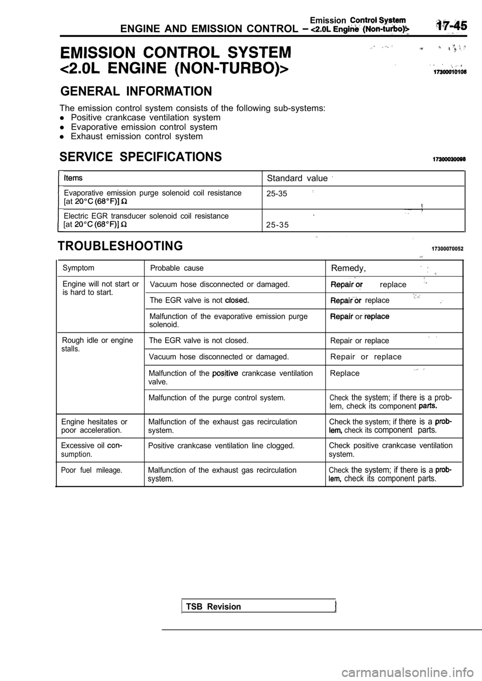
GENERAL INFORMATION
The emission control system consists of the following sub-systems:
l Positive crankcase ventilation system
l Evaporative emission control system
l Exhaust emission control system
SERVICE SPECIFICATIONS
Evaporative emission purge solenoid coil resistance
[at
Electric EGR transducer solenoid coil resistance
[at
Standard value
25-35
.
2 5 - 3 5
TROUBLESHOOTING17300070052
Symptom Probable causeRemedy,
Engine will not start or
Vacuum hose disconnected or damaged. replace is hard to start.
The EGR valve is not replace
Malfunction of the evaporative emission purge or solenoid.
Rough idle or engineThe EGR valve is not closed. Repair or replace
stalls.Vacuum hose disconnected or damaged.Repair or replace
Malfunction of the crankcase ventilationReplace
valve.
Malfunction of the purge control system.
Checkthe system; if there is a prob-
lem, check its component
Engine hesitates or
poor acceleration.
Excessive oil
sumption.
Poor fuel mileage.
Malfunction of the exhaust gas recirculation
system.
Positive crankcase ventilation line clogged.
Malfunction of the exhaust gas recirculation
system.
Check the system; if there is a
check its component parts.
Check positive crankcase ventilation
system.
Checkthe system; if there is a
check its component parts.
TSB Revision
Page 798 of 2103
ENGINE AND EMISSION CONTROL
INSPECTION
Check for damage, cracking or deterioration. Replace if faulty.
Caution
1. Stop the engine immediately if engine misfiring
occurs, otherwise an abnormally hot exhaust system
will damage the catalytic converter or other underb ody
parts.
2.
Correct and repair the ignition or fuel system if t here
are malfunctions, otherwise engine misfiring may
occur which will damage the catalytic converter.
3. Observe manufacturer’s specifications when doing
service work.
TSB Revision
Page 799 of 2103

(Turbo) 2.41 Engines
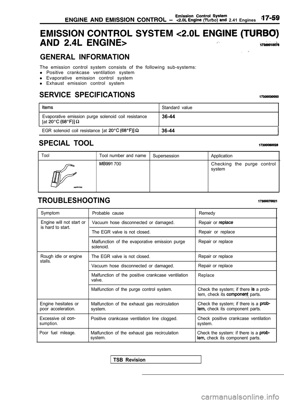
GENERAL INFORMATION
The emission control system consists of the following sub-systems:
l Positive crankcase ventilation system
l Evaporative emission control system
l Exhaust emission control system
SERVICE SPECIFICATIONS
Evaporative emission purge solenoid coil resistance
[at
Standard value
36-44
EGR solenoid coil resistance [at 36-44
SPECIAL TOOL
ToolTool number and name
Supersession Application
700Checking the purge control
system
TROUBLESHOOTING
SymptomProbable cause Remedy
Engine will not start or Vacuum hose disconnected or damaged. Repair or
is hard to start.
The EGR valve is not closed. Repair or replace
Malfunction of the evaporative emission purge Repair or replace
solenoid.
Rough idle or engine
stalls.The EGR valve is not closed.
Vacuum hose disconnected or damaged.
Malfunction of the positive crankcase ventilation
valve. Repair or replace
Repair or replace
Replace
Malfunction of the purge control system.
Engine hesitates or
poor acceleration.
Excessive oil
sumption.
Poor fuel mileage.
Malfunction of the exhaust gas recirculation
system.
Positive crankcase ventilation line clogged.
Malfunction of the exhaust gas recirculation
system. Check the system; if there
a prob-
lem, check its
parts.
Check the system; if there is a
check its component parts.
Check positive crankcase ventilation
system.
Check the system: if there is a
check its component parts.
TSB Revision
Page 828 of 2103

Emission Control System ENGINE AND EMISSION CONTROL Engine (Turbo) and
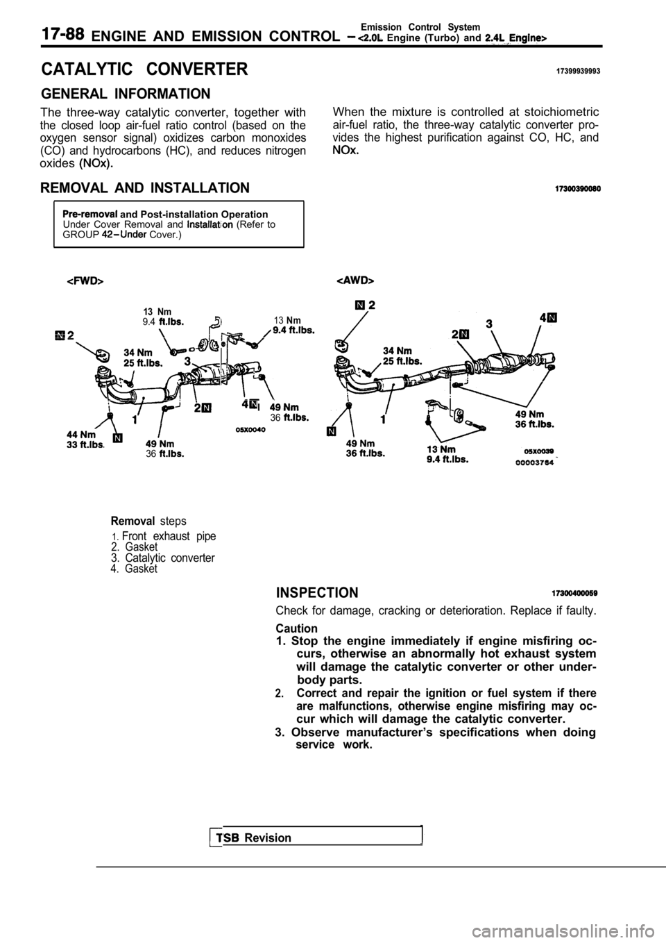
CATALYTIC CONVERTER17399939993
GENERAL INFORMATION
The three-way catalytic converter, together with
the closed loop air-fuel ratio control (based on the
oxygen sensor signal) oxidizes carbon monoxides
(CO) and hydrocarbons (HC), and reduces nitrogen
oxides
REMOVAL AND INSTALLATION
When the mixture is controlled at stoichiometric
air-fuel ratio, the three-way catalytic converter p ro-
vides the highest purification against CO, HC, and
and Post-installation Operation
Under Cover Removal and (Refer to
GROUP Cover.)
13 Nm9.413Nm
I36
. .
Revision
36
Removalsteps
1.Front exhaust pipe2. Gasket3. Catalytic converter4. Gasket
INSPECTION
Check for damage, cracking or deterioration. Replac e if faulty.
Caution
1. Stop the engine immediately if engine misfiring oc-
curs, otherwise an abnormally hot exhaust system
will damage the catalytic converter or other under- body parts.
2.Correct and repair the ignition or fuel system if t here
are malfunctions, otherwise engine misfiring may oc -
cur which will damage the catalytic converter.
3. Observe manufacturer’s specifications when doing
service work.
Page 831 of 2103
C O N T E N T S
CLUTCH CONTROL . . . . . . . . . . . . . . . . . . . . . . . 10
CLUTCH MASTER CYLINDER . . . . . . . . . . . . . 13
Bleeding. . . . . . . . . . . . . . . . . . . . . . . . . . . . . . . . . .‘7
Clutch Pedal Check and . . . . . . .
Interlock Switch Check and Adjustment . . . . . . . . 6
CLUTCH PEDAL
. . . . . . . . . . . . . . . . . . . . . . . . . . .8Interlock Switch Operating Check . . . . . . . . . . . . . 6
GENERAL INFORMATION2SERVICE SPECIFICATIONS. . . . . . . . . . . . . . . . .3. . . . . . . . . . . . . . . . . .
LUBRICANTS. . . . . . . . . . . . . . . . . . . . . . . . . . . . . .3TROUBLESHOOTING. . . . . . . . . . . . . . . . . . . . . . .4
ON-VEHICLE SERVICE. . . . . . . . . . . . . . . . . . . . .5
Page 833 of 2103
CLUTCH Service Specifications/Lubricants
SERVICE SPECIFICATIONS
Clutch pedal height mm (in.)
Clutch pedal
pin play mm (in.)
Clutch pedal free play mm (in.) Distance between the clutch pedal and
the
when the clutch is disengaged mm (in.)
LUBRICANTS
Standard value
6-13
70 (2.76) or more
Items
Clutch fluid
Push rod assembly
Boot
Specified lubricants
Brake Fluid DOT 3 or DOT 4
Rubber grease
Q u a n t i t y
A s r e q u i r e d
As required
Release cylinder push rod MITSUBISHI genuine grease
Part No. 0101011 or equivalentAs required
Clutch pedal shaft, bushings and end of the Brake grease SAE
No. 1As required
pedal
Clutch master cylinder push rod, pin
and washer
Clutch release cylinder
pin
Revision
Page 835 of 2103

CLUTCH -On-vehicle Service
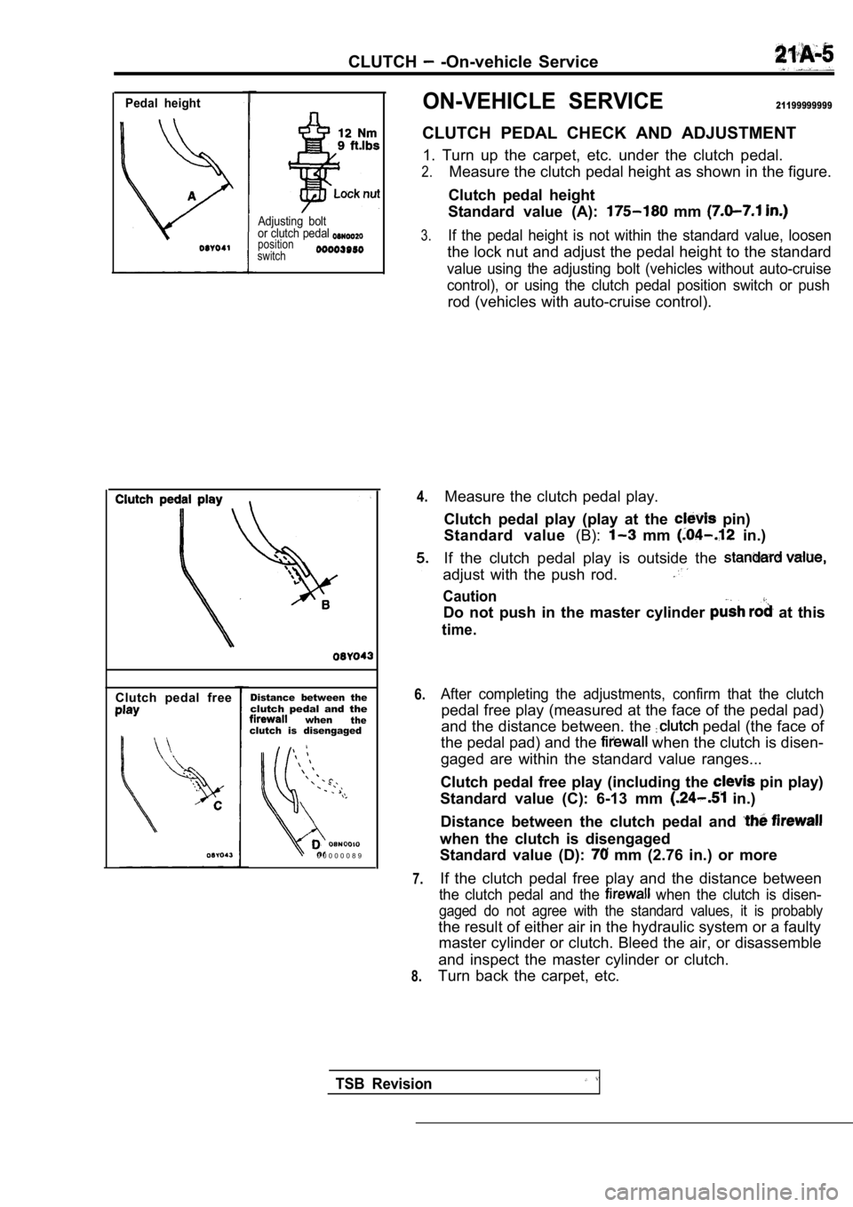
Pedal height
Adjusting bolt
or clutch pedal
position
switch
Clutch pedal freeDistance between theclutch pedal and thewhentheclutch is disengaged
0 0 0 0 0 0 8 9
ON-VEHICLE SERVICE21199999999
CLUTCH PEDAL CHECK AND ADJUSTMENT
1. Turn up the carpet, etc. under the clutch pedal.
2.Measure the clutch pedal height as shown in the fig ure.
Clutch pedal height
Standard value (A):
mm
3.If the pedal height is not within the standard valu e, loosen
the lock nut and adjust the pedal height to the sta ndard
value using the adjusting bolt (vehicles without au to-cruise
control), or using the clutch pedal position switch or push
rod (vehicles with auto-cruise control).
4.
6.
7.
8.
Measure the clutch pedal play.
Clutch pedal play (play at the
pin)
Standard value (B):
mm in.)
If the clutch pedal play is outside the
adjust with the push rod.
Caution
Do not push in the master cylinder at this
time.
After completing the adjustments, confirm that the clutch
pedal free play (measured at the face of the pedal pad)
and the distance between. the
pedal (the face of
the pedal pad) and the
when the clutch is disen-
gaged are within the standard value ranges...
Clutch pedal free play (including the
pin play)
Standard value (C): 6-13 mm
in.)
Distance between the clutch pedal and
when the clutch is disengaged
Standard value (D):
mm (2.76 in.) or more
If the clutch pedal free play and the distance betw een
the clutch pedal and the when the clutch is disen-
gaged do not agree with the standard values, it is probably
the result of either air in the hydraulic system or a faulty
master cylinder or clutch. Bleed the air, or disass emble
and inspect the master cylinder or clutch.
Turn back the carpet, etc.
TSB Revision