Page 347 of 2103

E N G I N E O V E R H A U L Cylinder Head and
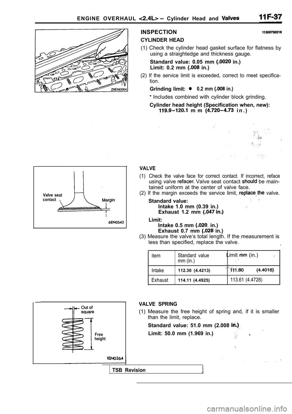
Valve seatcontact
I
Free
height
INSPECTION
CYLINDER HEAD (1) Check the cylinder head gasket surface for flat ness by
using a straightedge and thickness gauge.
Standard value: 0.05 mm
in.)
Limit: 0.2 mm
in.)
(2) If the service limit is exceeded, correct to me et specifica-
tion.
Grinding limit:l 0.2 mm in.)
Includes combined with cylinder block grinding.
Cylinder head height (Specification when, new):
m m i n . )
VALVE
(1) Check the valve face for correct contact. If incorr ect, reface
using valve Valve seat contact be main-
tained uniform at the center of valve face.
(2) If the margin exceeds the service limit, valve.
Standard value:
Intake 1.0 mm (0.39 in.)
Exhaust 1.2 mm
Limit:
Intake 0.5 mm in.)
Exhaust 0.7 mm
in.)
(3) Measure the valve’s total length. If the measur ement is
less than specified, replace the valve.
item Standard value
mm (in.)
Limit (in.)
Intake112.30 (4.4213)
Exhaust114.11 (4.4925)113.61 (4.4728)
VALVE SPRING
(1) Measure the free height of spring and, if it is
smaller
than the limit, replace.
Standard value: 51.0 mm (2.008
Limit: 50.0 mm (1.969 in.) ,
TSB Revision
Page 351 of 2103
Front Case,
E N G I N E Shaft
REMOVAL SERVICE POINTS
PAN REMOVAL
(1) Remove all oil pan bolts.
(2) Drive in the special tool
the cylinder, block and
oil pan.
NOTE
Never use a screwdriver or chisel, instead service
tool, as a deformed oil pan will result in oil leakage.
PLUG REMOVAL
If the plug is too tight, hit the plug head with a hammer two
to three times, and the plug will be easily loosene d.
FLANGE BOLT REMOVAL
(1) Remove the plug on the side of
block.
(2) Insert a Phillips screwdriver [shank diameter 8 mm
in.)] into the plug hole, to lock the counterbalanc e shaft.,
(3) Loosen the flange bolt.
COUNTERBALANCE SHAFT FRONT BEARING
REMOVAL
Using the special tool, remove the shaft
front bearing from the cylinder block.
NOTE
Be sure to remove the front bearing
If it has not been removed, the Rear Bearing Puller cannot
be used.
TSB Revision
Page 359 of 2103
ENGINE OVERHAUL Piston and
number
Piston Din tool
11
REMOVAL SERVICE POINTS
ROD CAP REMOVAL
Mark the cylinder number on the side of
rod big end for correct reassembly..
(2) Keep the removed connecting rods, caps, and bearings
in order according to the cylinder
PISTON PIN REMOVAL
1
2I Connecting Pin
4
5 Rod
Piston Support
7Connecting Pin
8
Piston Support
9 43P r e s s P i n
10216943Stop Screw
1110396Nut
(1) Remove the stop screw from the base.
(2) Select the correct piston support for your appl ication
above). Fit the piston support the base. Place the’
base
press support blocks.
TSB Revision
Page 360 of 2103

ENGINE OVERHAUL Piston and Rod
TSB Revision
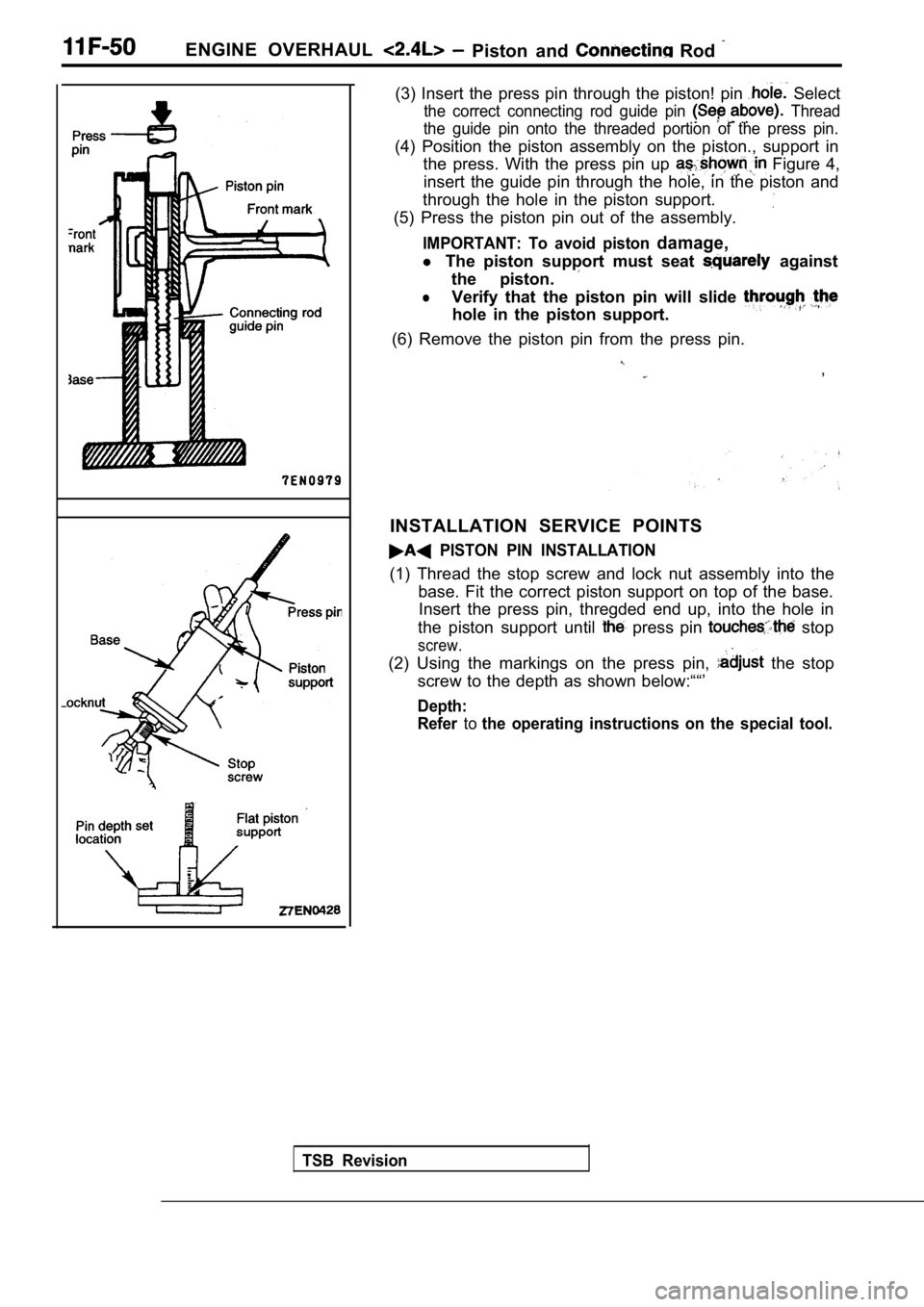
(3) Insert the press pin through the piston! pin Select
the correct connecting rod guide pin Thread
the guide pin onto the threaded portion of the pres s pin.
(4) Position the piston assembly on the piston., support in
the press. With the press pin up
Figure 4,
insert the guide pin through the hole, in the pisto n and
through the hole in the piston support.
(5) Press the piston pin out of the assembly.
IMPORTANT: To avoid piston damage,
l The piston support must seat against
the piston.
lVerify that the piston pin will slide
hole in the piston support.
(6) Remove the piston pin from the press pin.
,
INSTALLATION SERVICE POINTS
PISTON PIN INSTALLATION
(1) Thread the stop screw and lock nut assembly int o the
base. Fit the correct piston support on top of the base.
Insert the press pin, thregded end up, into the hol e in
the piston support until
press pin stop
screw.
(2) Using the markings on the press pin, the stop
screw to the depth as shown below:““’
Depth:
Refer
tothe operating instructions on the special tool.
Page 363 of 2103

ENGINE OVERHAUL Piston Rod
Timing belt side
Identification mark
(4) thread protectors on the connecting
before inserting piston and assembly into
the. block.
Care’ must be taken not to nick crank
Using a suitable piston. the
piston and connecting rod block.
CONNECTING ROD
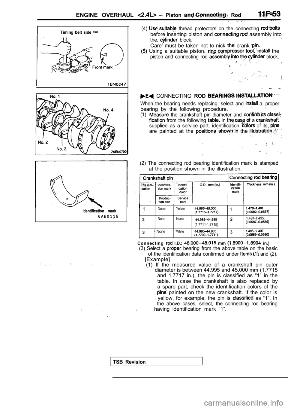
When the bearing needs replacing, select and a, proper
bearing by the following procedure.
(1) the crankshaft pin diameter and
from the following In a
supplied as a service part, identification of its,
are painted at the the
. .,
(2) The connecting rod bearing identification mark is stamped
at the position shown in the illustration.
NoneYellow1
2None None21.491-1.495
(1.7711-1.7715)
3 None‘White3
C o n n e c t i n g I.D.: mm in.)
(3) Select a bearing from the above table on the basic
of the identification data confirmed under
and (2).
[Example]
(1) If the measured value of a crankshaft pin outer diameter is between 44.995 and 45.000 mm (1.7715
and 1.7717 in.), the pin is classified as “1” in th e
table. In case the crankshaft is also replaced by
a spare part, check the identification colors of th e
painted on the new crankshaft. If the color is
yellow, for example, the pin is as “1”. In
the above cases, select, the connecting rod bearing
having identification mark “1”.
TSB Revision
Page 368 of 2103

ENGINE OVERHAUL Crankshaft,
Timing belt side
Cylinder block bearing boreidentification mark
Lower bearing No.
Identification
mark
Upper bearing (for No.
Identification
mark
1
SERVICE
CRANKSHAFT BEARING
When the bearing needs replacing, select and instal l a proper
bearing by the following procedure.
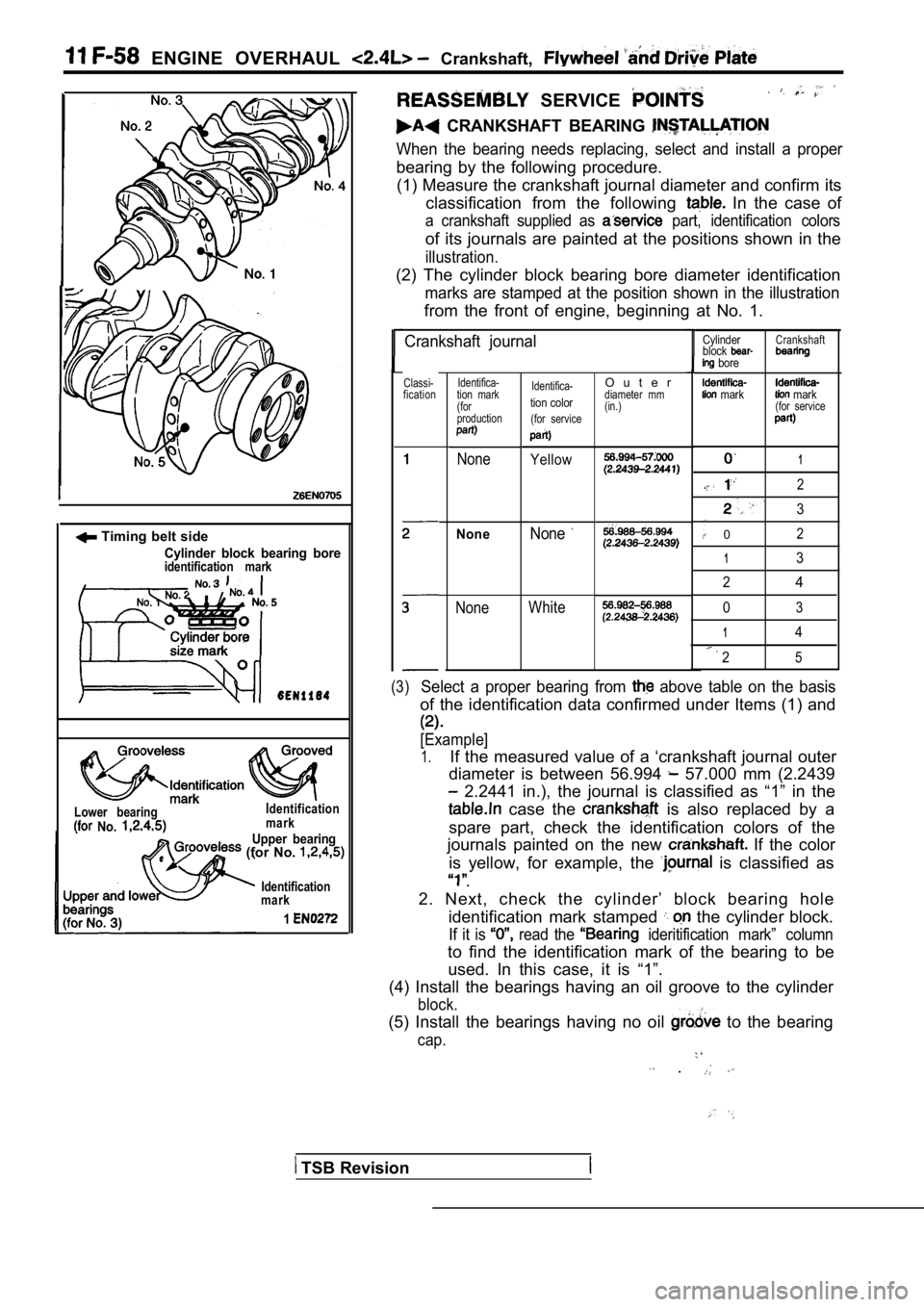
(1) Measure the crankshaft journal diameter and con firm its
classification from the following
In the case of
a crankshaft supplied as part, identification colors
of its journals are painted at the positions shown in the
illustration.
(2) The cylinder block bearing bore diameter identi fication
marks are stamped at the position shown in the illustration
from the front of engine, beginning at No. 1.
Crankshaft journal
Classi-
fication Identifica-
tion mark
(for
production
None
NoneNone
Identifica-
tion color
(for service
Yellow
WhiteNone
1
2
3
02
13
2
4
03
14
25
(3)Select a proper bearing from above table on the basis
of the identification data confirmed under Items (1 ) and
[Example]
1.If the measured value of a ‘crankshaft journal oute r
diameter is between 56.994
57.000 mm (2.2439
2.2441 in.), the journal is classified as “1” in t he
case the is also replaced by a
spare part, check the identification colors of the
journals painted on the new
If the color
is yellow, for example, the
is classified as
.
2. Next, check the cylinder’ block bearing hole identification mark stamped
the cylinder block.
If it is read the ideritification mark” column
to find the identification mark of the bearing to b e
used. In this case, it is “1”.
(4) Install the bearings having an oil groove to th e cylinder
block.
(5) Install the bearings having no oil to the bearing
cap.
.
O u t e rdiameter mm
(in.)
Cylinder
block
bore
mark
Crankshaft
mark(for service
TSB Revision
Page 373 of 2103
ENGINE
.
CONTENTS
ENGINE OIL COOLER.. . . . . . . . . . . . . . . . . . . . . ON-VEHICLE SERVICE . . . . . . . . . . . . . . . . . . . 3
GENERAL INFORMATION. . . . . . . . . . . . . . . . . . 2Engine Oil . . . . . . . . . . . . . . . . . . . . . . . . .
Engine Oil Replacement . . . . . . . . . . . . . . . . . . . .3
LUBRICANTS. . . . . . . . . . . . . . . . . . . . . . . . . . . . . .2Oil Filter Replacement . . . . . . . . . . . . . . . . . . . . .
4
Page 375 of 2103
ENGINE LUBRICATION Service
DraingasketOil pan side
Engine (Non-turbo)>
If these oils are not available, an API classificat
ion
or can be used.’ . .
ON-VEHICLE
ENGINE OIL
.
Pull out the oil dipstick slowly and check that the oil
is within the marks on the oil dipstick.
2.Check that the oil is dirty, that there is
no coolant or gasoline mixed in, ‘and that it has, sufficient
viscosity.
ENGINE OIL REPLACEMENT
After warming up the engine, remove the oil filler cap.
2.Remove the drain plug to allow the engine oil to drain.
3.Replace the drain plug gasket with a new one and ti ghten
the drain plug.