Page 307 of 2103
E N G I N E Timing belt
REMOVAL AND INSTALLATION
Nm
R e m o v a l s t e p s
2 .
l
REMOVAL SERVICE
SPROCKET
(1) Use the special tool to remove bolt.
Use the special tool to remove crankshaft sprocket.
Page 308 of 2103

ENGINE Timing Belt
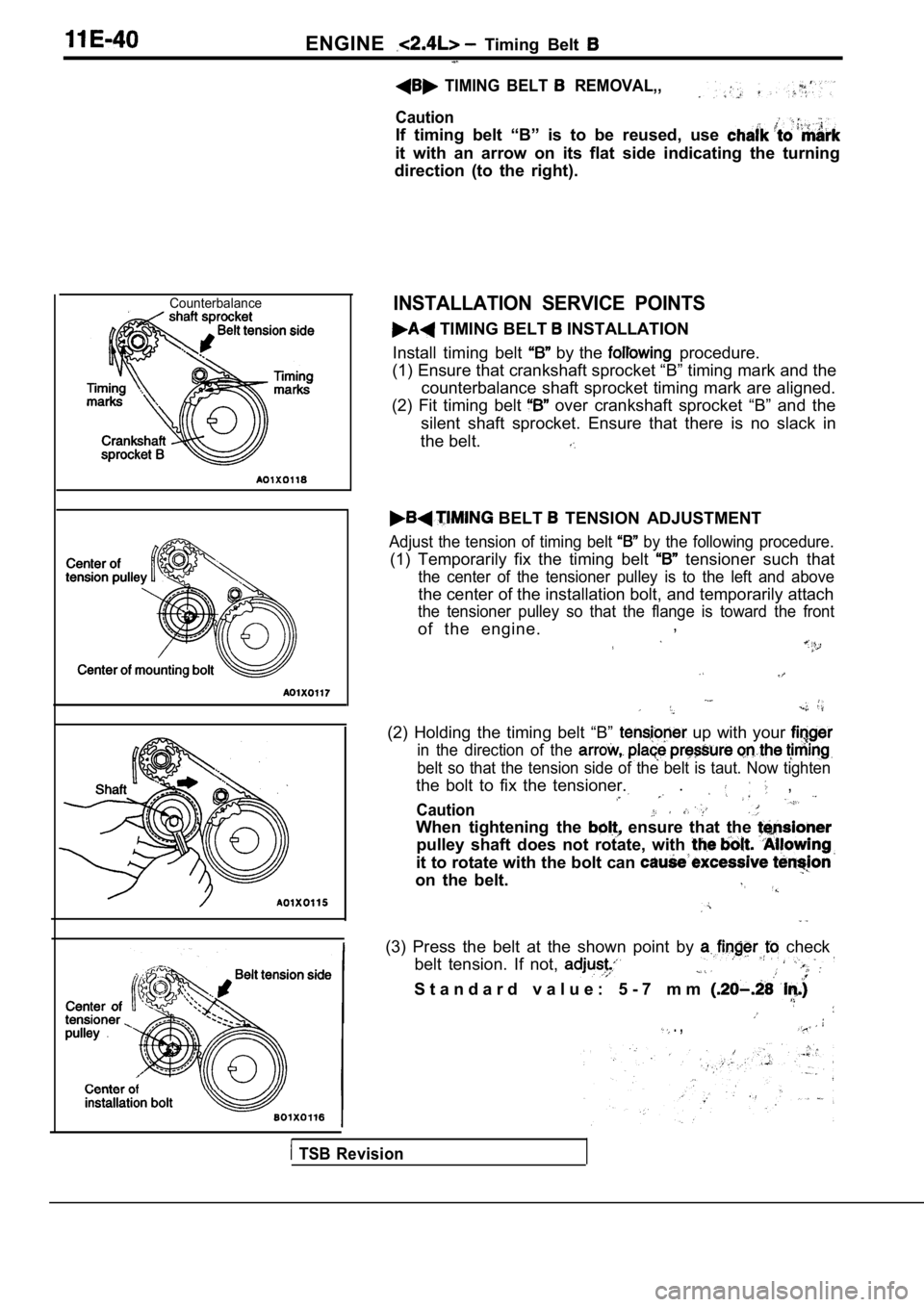
TIMING BELT REMOVAL,,
Caution
If timing belt “B” is to be reused, use
it with an arrow on its flat side indicating the tu rning
direction (to the right).
CounterbalanceINSTALLATION SERVICE POINTS
TIMING BELT INSTALLATION
Install timing belt
by the procedure.
(1) Ensure that crankshaft sprocket “B” timing mark and the
counterbalance shaft sprocket timing mark are align ed.
(2) Fit timing belt
over crankshaft sprocket “B” and the
silent shaft sprocket. Ensure that there is no slac k in
the belt.
BELT TENSION ADJUSTMENT
Adjust the tension of timing belt by the following procedure.
(1) Temporarily fix the timing belt tensioner such that
the center of the tensioner pulley is to the left a nd above
the center of the installation bolt, and temporarily attach
the tensioner pulley so that the flange is toward t he front
of the engine.,
(2) Holding the timing belt “B” up with your
in the direction of the
belt so that the tension side of the belt is taut.
Now tighten
the bolt to fix the tensioner.. ,
Caution
When tightening the ensure that the
pulley shaft does not rotate, with
it to rotate with the bolt can
on the belt.
(3) Press the belt at the shown point by check
belt tension. If not,
S t a n d a r d v a l u e : 5 - 7 m m
. ,
TSB Revision
Page 313 of 2103
OVERHAUL Specifications
SERVICE SPECIFICATIONS
Timing belt
.Rocker arms and camshaft
36.97 (1.4555)
Cvlinder head and valves
TSB Revision
Page 324 of 2103
ENGINE OVERHAUL Timing Belt , ,
REMOVAL SERVICE POINTS
TIMING BELT REMOVAL
Mark belt running direction for reinstallation.
NOTE
(1) Water or oil on the belt shorten its life drastically, so the
removed timing belt, sprocket, and tensioner must b e
free from oil and water. These parts should not be washed.
Replace parts if seriously contaminated.
(2) If there is oil or water on each part check fro nt case
oil seals, camshaft oil seal and water pump for lea ks.
OIL PUMP SPROCKET REMOVAL
CRANKSHAFT BOLT LOOSENING
CRANKSHAFT SPROCKET REMOVAL
BELT “B”
(1) Make a mark on the back of the timing belt indi cating
the direction of rotation so it may be reassembled in the
same direction if it is to be reused.
NOTE
(1) Water or oil on the belt shortens life drastically,
so the removed timing belt, sprocket, and tensioner must be free from oil and
should
not be washed. Replace parts if seriously contami-
nated.
TSBRevision
Page 325 of 2103
ENGINE OVERHAUL Timing Belt
(2) If there is oil or water on each part check front case
oil seals, camshaft oil seal and water pump leaks.’
COUNTERBALANCE SHAFT SPROCKET
REMOVAL
SPROCKET “B” REMOVAL
CAMSHAFT SPROCKET BOLT LOOSENING
INSTALLATION SERVICE POINTS
CAMSHAFT SPROCKET
TSB RevisionI
Page 336 of 2103
ENGINE OVERHAUL intake Manifold
sealant
3 mm
bead sealant
INSTALLATION SERVICE ,
S E A L A N T TO
HOUSING
Specified sealant:Mitsubishi Genuine Part No.
or equivalent
NOTE
(1) Be sure to install the housing quickly while sealant
is wet (within 15 minutes).
(2) After installation, keep the sealed area away f rom the
oil and coolant for approx. one hour.
SEALANT APPLICATION TO WATER
FITTING
S p e c i f i e d s e a l a n t :
Mitsubishi Genuine Part No.’ or equivalent
NOTE
(1) Be sure to install the housing quickly while th e sealant
is wet (within 15 minutes).
(2) After installation, keep the sealed area away f rom the
oil and coolant for approx. one hour.
SEALANT APPLICATION COOLANT
T E M P E R A T U R E S E N S O R
Specified sealant:
Nut Locking Part No. or equivalent
SEALANT APPLICATION TO ENGINE COOLANT TEMPERATURE GAUGE UNIT
Specified sealant:
ATD Part No. 8680 or equivalent
TSB Revision
Page 340 of 2103

ENGINE OVERHAUL Rocker Arms and Camshaft
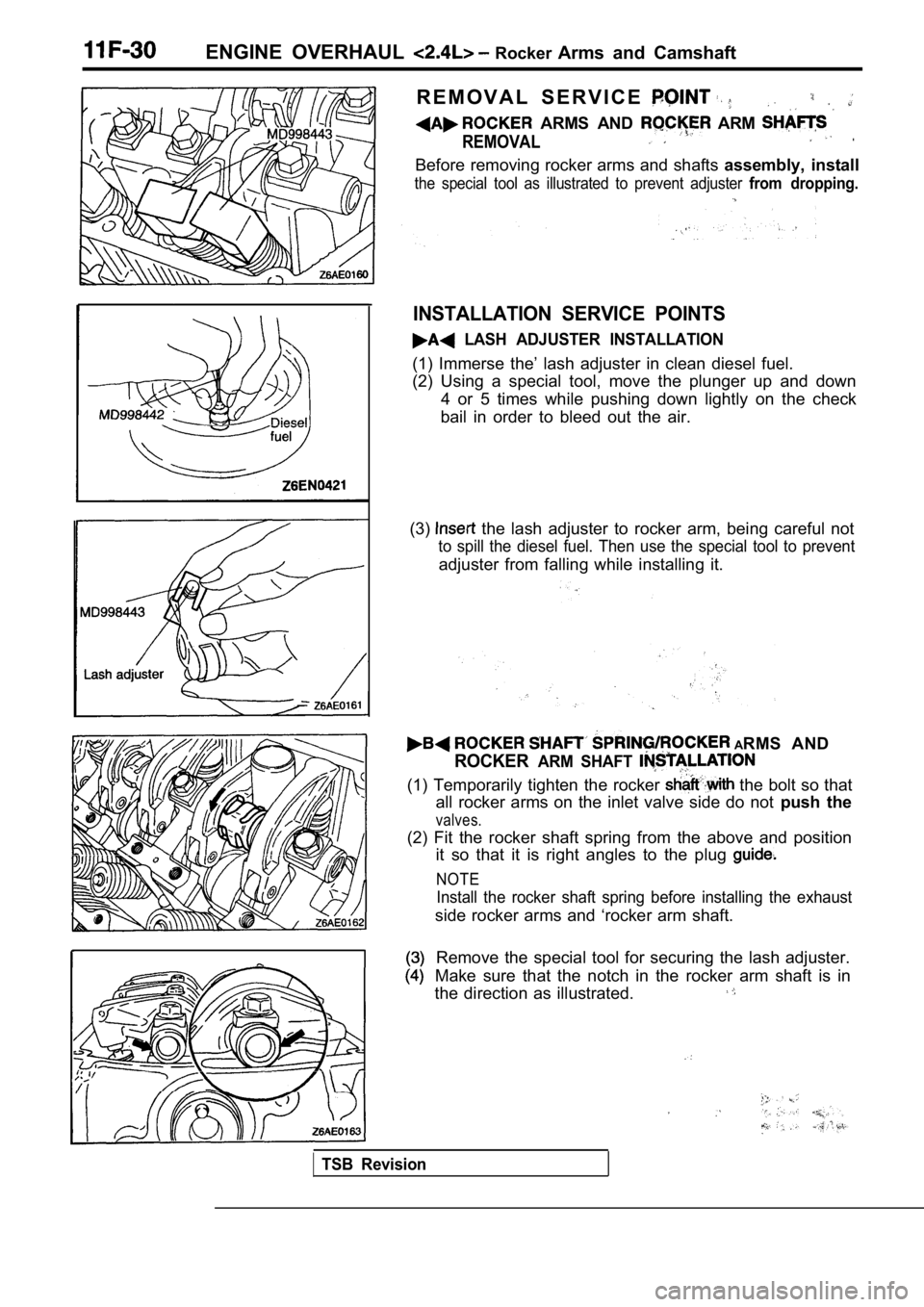
R E M O V A L S E R V I C E
ARMS AND ARM
REMOVAL.
Before removing rocker arms and shafts assembly, install
the special tool as illustrated to prevent adjuster from dropping.
INSTALLATION SERVICE POINTS
LASH ADJUSTER INSTALLATION
(1) Immerse the’ lash adjuster in clean diesel fuel .
(2) Using a special tool, move the plunger up and d own
4 or 5 times while pushing down lightly on the chec k
bail in order to bleed out the air.
(3)
the lash adjuster to rocker arm, being careful not
to spill the diesel fuel. Then use the special tool to prevent
adjuster from falling while installing it.
ARMS AND
ROCKERARM SHAFT
(1) Temporarily tighten the rocker the bolt so that
all rocker arms on the inlet valve side do not push the
valves.
(2) Fit the rocker shaft spring from the above and position
it so that it is right angles to the plug
NOTE
Install the rocker shaft spring before installing t he exhaust
side rocker arms and ‘rocker arm shaft.
Remove the special tool for securing the lash adjus ter.
Make sure that the notch in the rocker arm shaft is in
the direction as illustrated.
TSB Revision
Page 345 of 2103
E N G I N E O V E R H A U L Cylinder Head and Valves
color
REMOVAL SERVICE
PRECAUTION FOR PARTS
Keep removed parts in order according to cylinder
and intake/exhaust.
CYLINDER HEAD BOLTS
Using the special tool, loosen head bolts. Loosen
evenly, little by little.
LOCK REMOVAL
Store removed valves, springs and other parts, tagg ed to
indicate their cylinder No. and location for reasse mbly.
STEM SEAL REMOVAL
Do not reuse valve stem seal.
INSTALLATION SERVICE POINTS
VALVE STEM SEAL INSTALLATION
(1) Install’ the valve spring seat.
(2) The special tool must be’used install
seal. Improper installation in oil leaking
the valve guide.
Caution
Do not reuse the valve stem seal.
VALVE SPRINGS INSTALLATION
Direct the valve spring end with identification col or end toward
the spring retainer.
TSB Revision