Page 479 of 2103
![MITSUBISHI SPYDER 1990 Service Repair Manual ENGINE ( N O N - T U R B O ) >
INSPECTION PROCEDURE 25
Transaxle range sensor circuit
[Comment]The transaxle range sensor inputs the condition of the selector lever, i.e. whether it MITSUBISHI SPYDER 1990 Service Repair Manual ENGINE ( N O N - T U R B O ) >
INSPECTION PROCEDURE 25
Transaxle range sensor circuit
[Comment]The transaxle range sensor inputs the condition of the selector lever, i.e. whether it](/manual-img/19/57345/w960_57345-478.png)
ENGINE ( N O N - T U R B O ) >
INSPECTION PROCEDURE 25
Transaxle range sensor circuit
[Comment]The transaxle range sensor inputs the condition of the selector lever, i.e. whether it is in or range or in some other range, to the PCM.
The PCM controls the idle air control motor based o n this input.Improper connector contact, open circuit
Check the transaxle range sensor. (Refer to GROUP On-vehicle Service.) Replace.
lDisconnect the connector,and measure atthe harness
A-l
OK
Check trouble symptom.
OK
Replace the PCM.
Check harness wire betweenN G
PCM transaxle rangesensor connector.
O K
Replace the PCM.
,
INSPECTION PROCEDURE 26
A/C switch and A/C compressor clutch relay system
motor, and also operates the A/C compressor magneti c clutch.Probable cause
l Malfunction of A/C control l Malfunction of A/C switch Improper connector open short-circuited harness wire
l Malfunction of PCM
NG
OKCheck the A/C compressor clutch relay.
Measure at the PCM
l
(Refer to GROUP 55 On-vehicle Service.)
Disconnect the connector, and measure at the harnes s
Replace
Check the
system. (Refer to GROUP 55
side.lVoltage between 64 and ground, and 38 and ground(Ignition switch: ON)
(A/C switch: ON)
OK: Battery positive voltage
l Connect a jumper wire between 64 and ground.
(Ignition switch: ON)
(A/C switch: ON)
OK: A/C compressor clutch turns ON.
OK1NG RepairA-l 06,A-l 07
OK
Check trouble symptom.
Replace the PCM.
NG
TSB Revision
Page 499 of 2103

ENGINE (NON-TURBO)>
ON-VEHICLE SERVICE
THROTTLE BODY MINIMUM AIR FLOW
CHECK
1.Start the engine and warm it up until the engine co olant
is heated to
or higher and then stop the
engine.
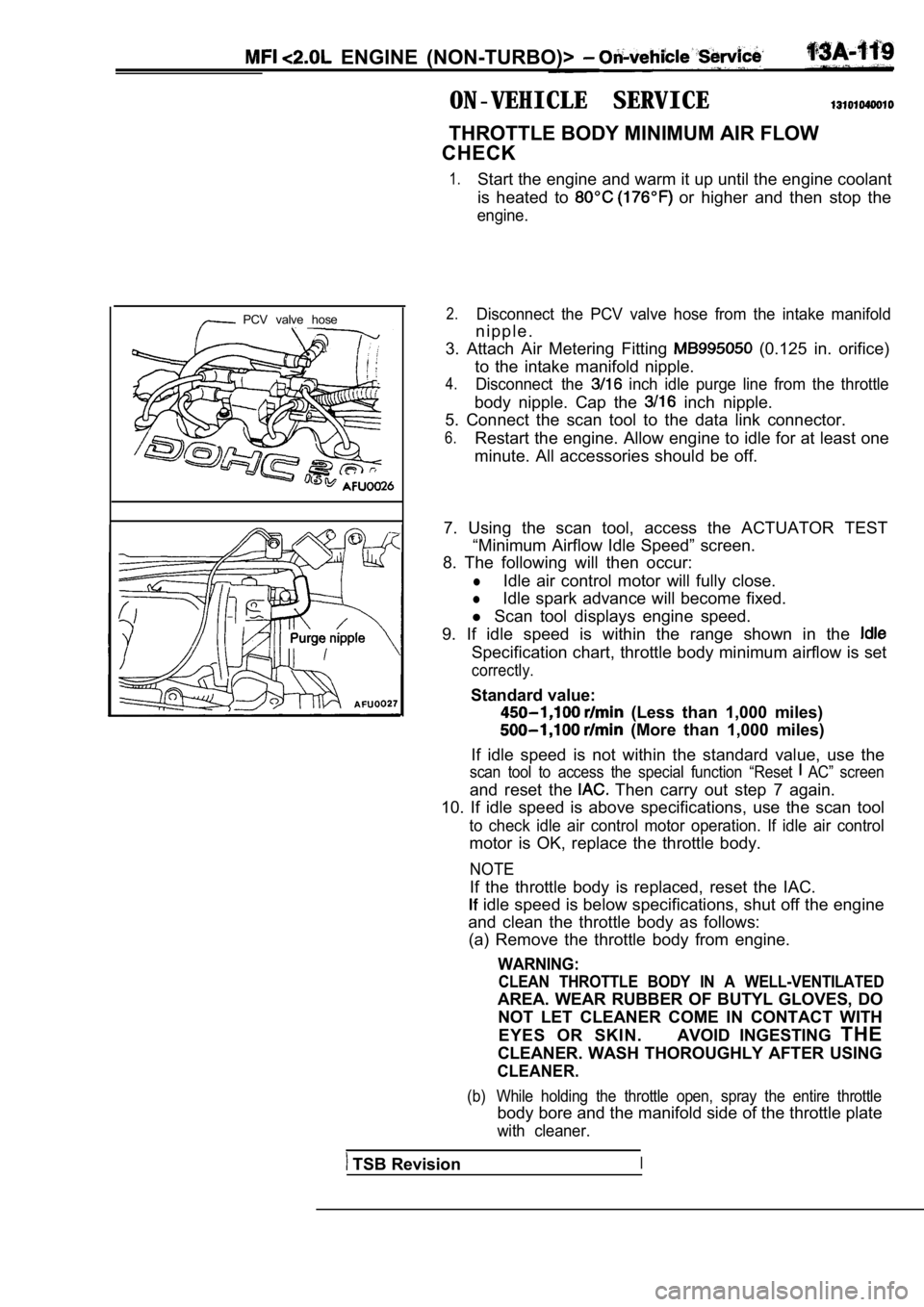
PCV valve hose2.Disconnect the PCV valve hose from the intake manif old
n i p p l e .
3. Attach Air Metering Fitting
(0.125 in. orifice)
to the intake manifold nipple.
4.Disconnect the inch idle purge line from the throttle
body nipple. Cap the inch nipple.
5. Connect the scan tool to the data link connector .
6.Restart the engine. Allow engine to idle for at least one
minute. All accessories should be off.
7. Using the scan tool, access the ACTUATOR TEST “Minimum Airflow Idle Speed” screen.
8. The following will then occur:
lIdle air control motor will fully close.
lIdle spark advance will become fixed.
l Scan tool displays engine speed.
9. If idle speed is within the range shown in the
Specification chart, throttle body minimum airflow is set
correctly.
Standard value:
(Less than 1,000 miles)
(More than 1,000 miles)
If idle speed is not within the standard value, use the
scan tool to access the special function “Reset AC” screen
and reset the Then carry out step 7 again.
10. If idle speed is above specifications, use the scan tool
to check idle air control motor operation. If idle air control
motor is OK, replace the throttle body.
NOTE
If the throttle body is replaced, reset the IAC.
idle speed is below specifications, shut off the e ngine
and clean the throttle body as follows: (a) Remove the throttle body from engine.
WARNING:
CLEAN THROTTLE BODY IN A WELL-VENTILATED
AREA. WEAR RUBBER OF BUTYL GLOVES, DO
NOT LET CLEANER COME IN CONTACT WITH
EYES OR SKIN. AVOID INGESTING THE
CLEANER. WASH THOROUGHLY AFTER USING
CLEANER.
(b) While holding the throttle open, spray the entir e throttle
body bore and the manifold side of the throttle plate
with cleaner.
TSB RevisionI
Page 501 of 2103

E N G I N E ,
FUEL PRESSURE TEST
FUEL SYSTEM PRESSURE MUST BE RELEASED BEFORE
A F U E L S Y S T E M H O S E O R C O M P O N E N T ’ “ I S
DISCONNECTED.
The specifications listed in the Fuel System Pressure Chart
are determined without vacuum applied to the fuel ‘ pressure,
regurator.
1.
2.
3.
4.
5.
Fuel system pressure must be released each time a f uel’
hose is to be disconnected. Release fuel system pre ssure.,
Remove protective cover from service valve on the fuel
rail.
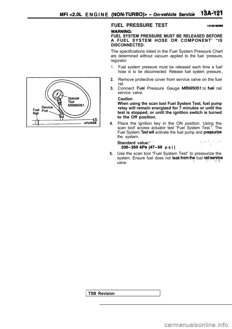
Connect Pressure Gauge to rail
service valve.
Caution
When using the scan tool Fuel System Test, fuel pum p
relay will remain energized for 7 minutes or until the
test is stopped, or until the ignition switch is tu rned
to the Off position.
Place the ignition key in the ON position. Using th e
scan tool! access actuator test “Fuel System Test.“. The
Fuel System
activate the fuel pump and
the system.
Standard value:’
p s i )
Use the scan tool “Fuel System Test” to pressurize the
system. Ensure fuel does not fuel
valve.
TSB Revision
Page 502 of 2103

ENGINE
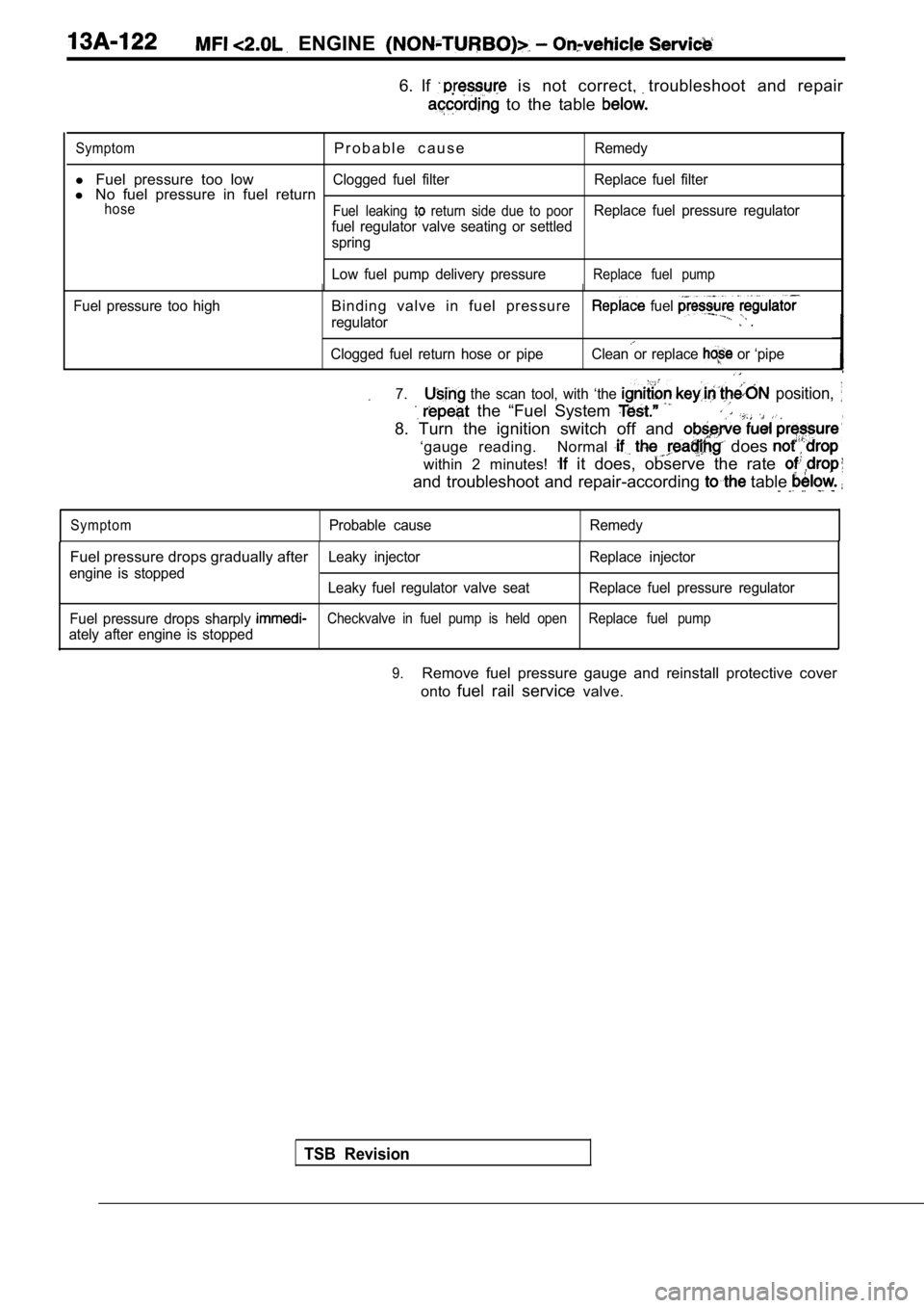
6. If is not correct, troubleshoot and repair
to the table
SymptomP r o b a b l e c a u s eRemedy
l Fuel pressure too lowClogged fuel filter Replace fuel filterl No fuel pressure in fuel returnhose
Fuel leaking return side due to poorReplace fuel pressure regulator
fuel regulator valve seating or settled
spring
Low fuel pump delivery pressure
Replace fuel pump
Fuel pressure too highBinding valve in fuel pressure
regulator
fuel .
Clogged fuel return hose or pipeClean or replace or ‘pipe
7. the scan tool, with ‘the position,
the “Fuel System ,
8. Turn the ignition switch off and
‘gauge reading. Normal does
within 2 minutes! it does, observe the rate
and troubleshoot and repair-according table
SymptomProbable cause Remedy
Fuel pressure drops gradually afterLeaky injector Replace injector
engine is stopped Leaky fuel regulator valve seat Replace fuel pressur e regulator
Fuel pressure drops sharply
Checkvalve in fuel pump is held open Replace fuel pu mp
ately after engine is stopped
TSB Revision
9.Remove fuel pressure gauge and reinstall protective cover
onto fuel rail service valve.
Page 515 of 2103
ENGINE (NON-TURBO)>
REMOVAL SERVICE POINT,
F U E L
Remove the fuel rail the attached’
,
Do not drop the injector.
INSTALLATION SERVICE POINTS
INJECTORS INSTALLATION
(1) Apply a small amount of clean engine oil to the O-ring.
Caution
Donot let the engine oil get into the fuel rail.
(2) While turning the injector to the left and righ t, install it
to the fuel rail.
(3) Check to be sure that the injector turns smooth ly.
If it does not turn smoothly, the O-ring may be tra pped,
remove the injector and then reinsert it into the f uel
and check again.
HIGH-PRESSURE FUEL HOSE CONNECTION
When connecting the high-pressure fuel hose to the fuel rail,
apply a small amount of engine oil to the hose union, and
then insert, being careful not to damage the O-ring .
Caution
Do not let the engine get .
TSB Revision
Page 517 of 2103
ENGINE (NON-TURBO)> Throttle Body
DISASSEMBLY AND REASSEMBLY
2.2
2I
. .
1. .
steps
1. motor assembly2. Throttle body
DISASSEMBLY SERVICE POINT
MOTOR REMOVAL
Do not disassemble the motor.
2.Do not immerse solvent to clean the sensor and moto r.
Clean them with shop towel.
THROTTLE BODY REMOVAL
1. Do not remove the throttle valve.
2. Check if the vacuum port or passage is clogged. Use
compressed air to clean the vacuum passage.
TSB Revision
Page 571 of 2103
![MITSUBISHI SPYDER 1990 Service Repair Manual ENGINE (TURBO)
AND ENGINE> Troubleshooting
Code No. Power Steering Pressure Sensor CircuitProbable cause
[Comment] Power pressure switch Backgroundl Open or shorted power steering MITSUBISHI SPYDER 1990 Service Repair Manual ENGINE (TURBO)
AND ENGINE> Troubleshooting
Code No. Power Steering Pressure Sensor CircuitProbable cause
[Comment] Power pressure switch Backgroundl Open or shorted power steering](/manual-img/19/57345/w960_57345-570.png)
ENGINE (TURBO)
AND ENGINE> Troubleshooting
Code No. Power Steering Pressure Sensor CircuitProbable cause
[Comment] Power pressure switch Backgroundl Open or shorted power steering pressurelWhen the steering wheel is kept in the position during driving, the power
s w i t c h or steering pressure switch will be momentarily turned off. E n g i n e c o n t r o l f a i l e d ’lThe enginecontrol module checks whetherthe powerste ering pressure switch momentarilyturns off during driving.
Check Area Engine coolant temperature is or higher.
l Driving and stopping ‘2 are repeated times or more.“1: Engine speed is 2,500 or higher, volumetric efficiency is 55% or higher, and this
condition continues for 2 seconds or more.
l 2: Engine speed is 600 or lower.
Judgement Criterial Power steering pressure switch stays on without cha nging.
NGCheck the power steering press On-vehicle Service) Replace
lDisconnect the connector and measure at the harness side.
NG
between ECM and power pressure switch
NG
the ECM. Replace the ECM.
Code No. Transmission Range Sensor Circuit
Malfunction (RPNDL Input)
[Comment]
Background
lWhen a malfunction of the park/neutral position swi tch is detected, the transaxle control
module outputs amalfunction signal to the engine control module.
Check Area, Judgement Criteria l
control module.
Check the TCM. (Refer to GROUP Troubleshooting.)
Repair
Repair
cause
l Park/neutral position switch failedlOpen or shorted park/neutral position switchcircuit, or loose connector.
l Engine control module failed.
Code No. Turbocharger Waste Gate Actuator
Malfunction
(Turbo)> Probable cause
l
Turbocharger waste gateactuator failed.
l Charging pressure control system failed.
l Engine control module failed.[Comment]
Background
lThe engine control module checks that the engine is not overcharged by always monitoringintake air volume.lThe engine control module protects the engine by shutting off fuel when an overcharged
condition is detected.
Check Area
Engine coolant temperature is higher than
Judgement Criterial Volumetric efficiency has continued to be not lower than 200% for 1.5 sec.
Check the turbocharger supercharging. (Refer to GROUP 15
On-vehicle Service.)
TSB Revision
Page 572 of 2103
![MITSUBISHI SPYDER 1990 Service Repair Manual ENGINE (TURBO)
AND
Code No. Turbocharger Waste Gate Solenoid
Malfunction
Engine (Turbo)>
Probable cause
[Comment]l Turbocharger waste gate solenoid BackgroundlThe engine control modu MITSUBISHI SPYDER 1990 Service Repair Manual ENGINE (TURBO)
AND
Code No. Turbocharger Waste Gate Solenoid
Malfunction
Engine (Turbo)>
Probable cause
[Comment]l Turbocharger waste gate solenoid BackgroundlThe engine control modu](/manual-img/19/57345/w960_57345-571.png)
ENGINE (TURBO)
AND
Code No. Turbocharger Waste Gate Solenoid
Malfunction
Engine (Turbo)>
Probable cause
[Comment]l Turbocharger waste gate solenoid BackgroundlThe engine control module checks current flows in t he turbocharger waste gate solenoidl loose connector.
drive circuit when the solenoid is ON and OFF. l Engine control module failed.
Check Areal Battery voltage is not lower than 10 V.
Judgement CriterialSolenoid coil surge voltage (system voltage V) is not detected when the turbochargerwaste gate solenoid is turned on/off.
Check the turbocharger
NG
(Refer to GROUP 15 On-vehicleService.) Replace
OK
Measure at the turbocharger waste gate pressure sol enoidconnectorlDisconnect the connector and measure at the harnessRepair, if necessary.
.
side.l Voltage between 2 and ground (Ignition switch: ON)
OK: Battery positive voltage
Measureat the ECM connector lDisconnect the connectorand measure at the harness
- 1 N G
Check the following con- Repair A-l 00
lVoltage between 11 and ground (Ignition switch: ON)
OK: Battery positive voltageOK
Check trouble symptom.
NG
,
RepairCheck the harness wire between ECM and Repair, if
Check trouble symptom.
N G
[Replace the ECM. ,
TSB Revision