1990 MITSUBISHI SPYDER service
[x] Cancel search: servicePage 377 of 2103

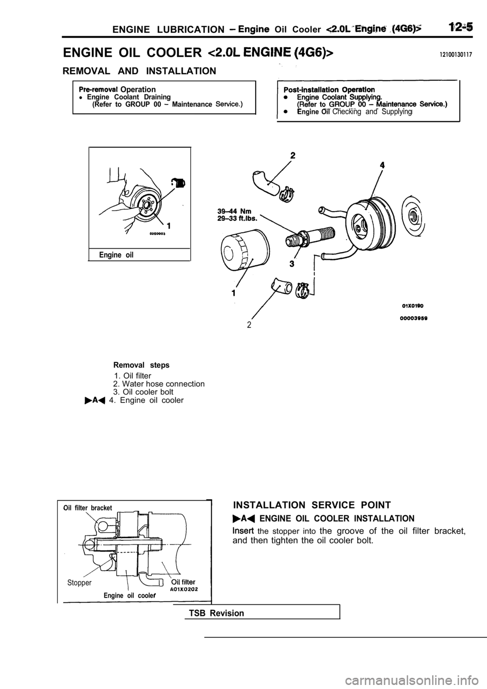
ENGINE LUBRICATION Oil Cooler
ENGINE OIL COOLER 12100130117
REMOVAL AND INSTALLATION
Operationl Engine Coolant Draining(Refer to GROUP 00 Maintenance
Engine oil
Engine Oil Checking and Supplying
2
Removal steps
1. Oil filter
2. Water hose connection
3. Oil cooler bolt
4. Engine oil cooler
Oil filter bracket
Stopper
Engine oil cooler
INSTALLATION SERVICE POINT
ENGINE OIL COOLER INSTALLATION
the stopper into the groove of the oil filter bracket,
and then tighten the oil cooler bolt.
TSB Revision
Page 381 of 2103

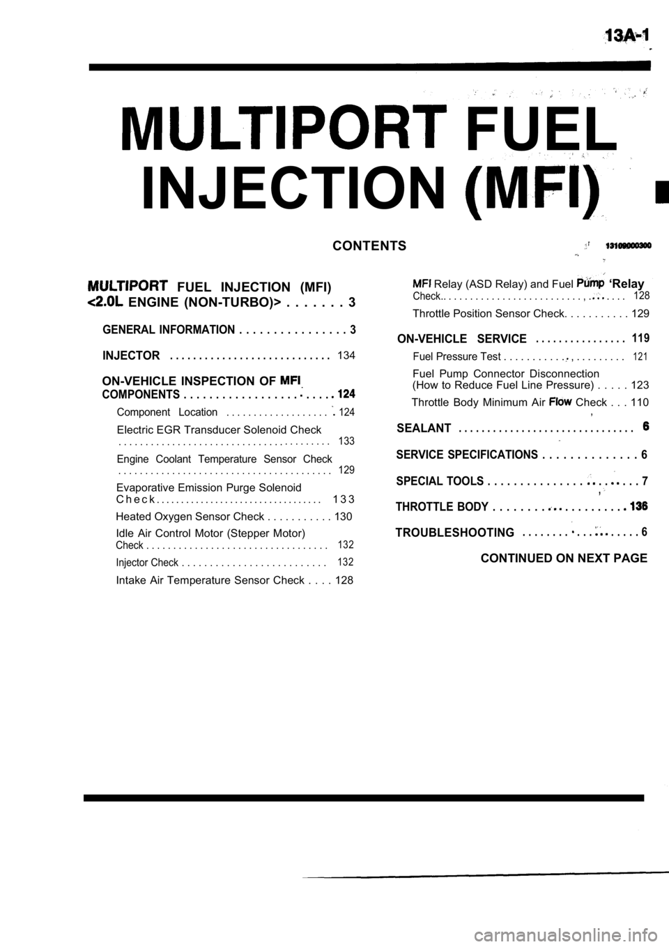
FUEL
INJECTION
CONTENTS
FUEL INJECTION (MFI)
ENGINE (NON-TURBO)> . . . . . . . 3
Relay (ASD Relay) and Fuel ‘Relay
Check.. . . . . . . . . . . . . . . . . . . . . . . . . . , . . . . .128
Throttle Position Sensor Check. . . . . . . . . . .
129
GENERAL INFORMATION . . . . . . . . . . . . . . . . 3ON-VEHICLE SERVICE. . . . . . . . . . . . . . . .119
INJECTOR. . . . . . . . . . . . . . . . . . . . . . . . . . . .134Fuel Pressure Test . . . . . . . . . . . , . . . . . . . . .121
ON-VEHICLE INSPECTION OF
COMPONENTS . . . . . . . . . . . . . . . . . . . . . .
Component Location. . . . . . . . . . . . . . . . . . . 124
Electric EGR Transducer Solenoid Check
. . . . . . . . . . . . . . . . . . . . . . . . . . . . . . .. . . . . . . . .133
Engine Coolant Temperature Sensor Check
. . . . . . . . . . . . . . . . . . . . . . . . . . . . . . . . . . . . . . . .129
Evaporative Emission Purge Solenoid
C h e c k . . . . . . . . . . . . . . . . . . . . . . . . . . . . . . . . . . 1 3 3
Heated Oxygen Sensor Check . . . . . . . . . . . 13 0
Idle Air Control Motor (Stepper Motor)
Check . . . . . . . . . . . . . . . . . . . . . . . . . . . . . . . . . .132
Injector Check . . . . . . . . . . . . . . . . . . . . . . . . . .132
Intake Air Temperature Sensor Check . . . . 128 Fuel Pump Connector Disconnection
(How to Reduce Fuel Line Pressure) . . . . . 123
Throttle Body Minimum Air
Check . . . 110 ,
SEALANT. . . . . . . . . . . . . . . . . . . . . . . . . . . . . . .
SERVICE SPECIFICATIONS . . . . . . . . . . . . . . 6
SPECIAL TOOLS . . . . . . . . . . . . . . .
. . . . . 7,
THROTTLE BODY . . . . . . . . . . . . . . . . .
TROUBLESHOOTING. . . . . . . . . . . . . . . . 6
CONTINUED ON NEXT PAGE
Page 382 of 2103

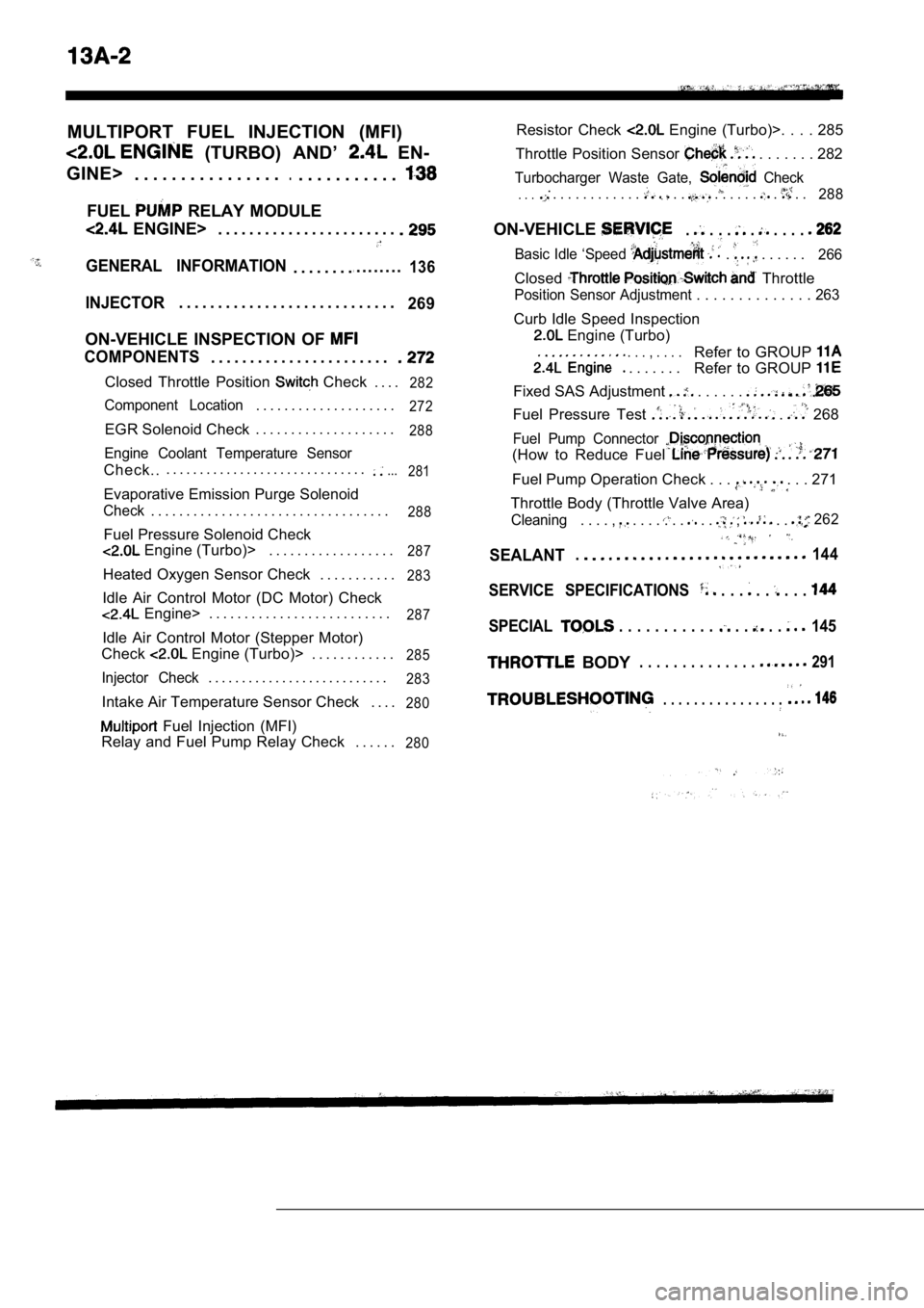
MULTIPORT FUEL INJECTION (MFI)
(TURBO) AND’ EN-
GINE> . . . . . . . . . . . . . . . .
.. . . . . . . . . . .
FUEL RELAY MODULE
ENGINE> . . . . . . . . . . . . . . . . . . . . . . .
GENERAL INFORMATION. . . . . . . ... . . . . . . .136
INJECTOR. . . . . . . . . . . . . . . . . . . . . . . . . . . .269
ON-VEHICLE INSPECTION OF
COMPONENTS. . . . . . . . . . . . . . . . . . . . . . .
Closed Throttle Position Check . . . .282
Component Location. . . . . . . . . . . . . . . . . . . .272
EGR Solenoid Check . . . . . . . . . . . . . . . . . . . .288
Engine Coolant Temperature Sensor
Check... . . . . . . . . . . . . . . . . . . . . . . . . . . . . ....
281
Evaporative Emission Purge Solenoid
Check. . . . . . . . . . . . . . . . . . . . . . . . . . . . . . . . . .288
Fuel Pressure Solenoid Check
Engine (Turbo)> . . . . . . . . . . . . . . . . . .287
Heated Oxygen Sensor Check . . . . . . . . . . .283
Idle Air Control Motor (DC Motor) Check
Engine> . . . . . . . . . . . . . . . . . . . . . . . . . .287
Idle Air Control Motor (Stepper Motor)
Check
Engine (Turbo)> . . . . . . . . . . . .285
Injector Check. . . . . . . . . . . . . . . . . . . . . . . . . . .283
Intake Air Temperature Sensor Check . . . .280
Fuel Injection (MFI)
Relay and Fuel Pump Relay Check . . . . . .
280
Resistor Check Engine (Turbo)>. . . . 285
Throttle Position Sensor
. . . . . . . 282
Turbocharger Waste Gate, Check.. . . . . . . . . . . . . . . . . . . . . . . . . .288
ON-VEHICLE. . . . . . . . .
Basic Idle ‘Speed . . . . . . . 266
Closed Throttle
Position Sensor Adjustment . . . . . . . . . . . . . . 263
Curb Idle Speed Inspection
Engine (Turbo)
. . . , . . . .
. . . . . . .
Refer to GROUP
Refer to GROUP
Fixed SAS Adjustment . . . . . .
Fuel Pressure Test . 268
Fuel Pump Connector
(How to Reduce Fuel
Fuel Pump Operation Check . . . . . . 271
Throttle Body (Throttle Valve Area)
Cleaning. . . . , . . . . . . . . . , . . 262
SEALANT.144
SERVICE SPECIFICATIONS . . . . . . . .
SPECIAL . . . . . . . . . . . . . . . 145
BODY. . . . . . . . . . . . . . 291
. . . . . . . . . . . . . . . .
Page 386 of 2103

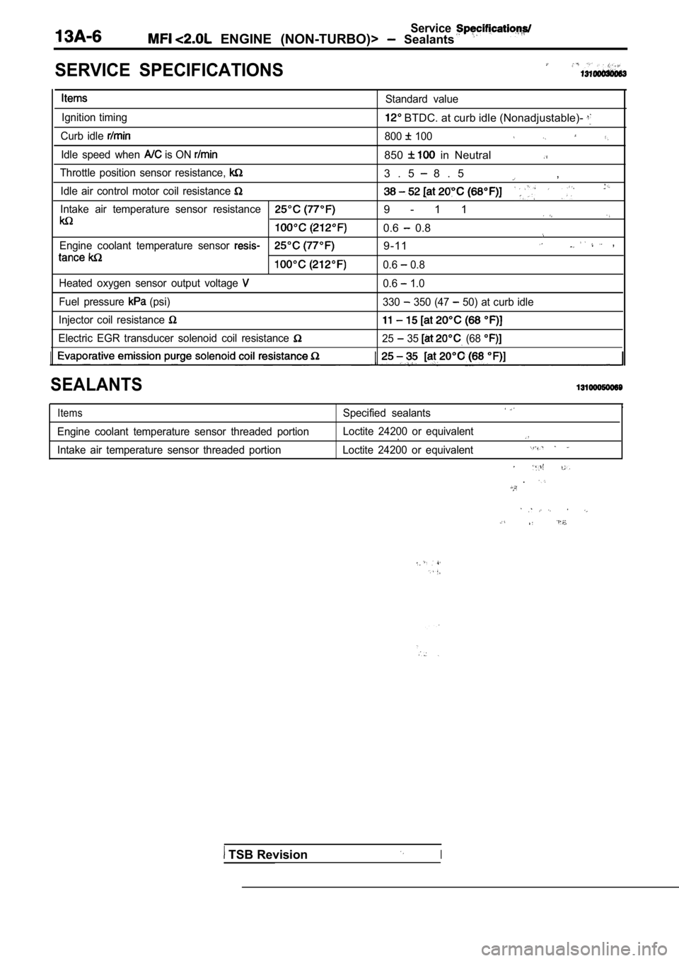
Service ENGINE (NON-TURBO)> Sealants
SERVICE SPECIFICATIONS
Ignition timing
Curb idle
Idle speed when is ON
Standard value
BTDC. at curb idle (Nonadjustable)-
800 100
850 in Neutral
Throttle position sensor resistance,
Idle air control motor coil resistance
Intake air temperature sensor resistance
Engine coolant temperature sensor
Heated oxygen sensor output voltage
Fuel pressure (psi)
Injector coil resistance
Electric EGR transducer solenoid coil resistance
3 . 5 8 . 5 ,
9 - 1 1
0.6 0.8
9-11 ,
0.6 0.8
0.6
1.0
330
350 (47 50) at curb idle
25 35 (68
SEALANTS
Items
Engine coolant temperature sensor threaded portion
Intake air temperature sensor threaded portion
,Specified sealants
Loctite 24200 or equivalent.
Loctite 24200 or equivalent
.
TSB RevisionI
Page 409 of 2103
![MITSUBISHI SPYDER 1990 Service Repair Manual Scan tool 16
General scan tool A/C Clutch Relay Circuit ,.
33
[Comment]Coinpressor clutch relay shortedBackgroundl control circuit defectivel The PCM provides a switched groun MITSUBISHI SPYDER 1990 Service Repair Manual Scan tool 16
General scan tool A/C Clutch Relay Circuit ,.
33
[Comment]Coinpressor clutch relay shortedBackgroundl control circuit defectivel The PCM provides a switched groun](/manual-img/19/57345/w960_57345-408.png)
Scan tool 16
General scan tool A/C Clutch Relay Circuit ,.
33
[Comment]Coinpressor clutch relay shortedBackgroundl control circuit defectivel The PCM provides a switched ground to the clutch relay.
l circuit driver in PCMlThe PCM can prevent operation of the clutch in selected situations such as duringwide-open or for a period at start-up.l This DTC indicates an open or short-circuit conditi on in the circuit.Range of Checkl Ignition ONl Battery voltage: or morel 30 seconds or more after starting engineSet ConditionlOpen or short circuit is detected in the A/C clutch relay control circuit for 3 seconds.
N G relay. Replace
. .
. 55 On-vehicle Service) me (Refer to GROUF
OK
Measure at the PCM connectors and lDisconnect the connector, and measure at the harnes s side.
l Voltage between 36 and ground, and 64 and ground
(Ignition switch: ON)
switch: ON)
OK: Battery positive
l Connect a jumper wire between and the ground.
(Ignition switch: ON)
(A/C switch: ON)
OK:
compressor clutch is turned on
N G
Check the system (Refer to GROUP 55 Troubleshooting) Check trouble symptom.
NG
Replace the . ,
I ,
TSB Revision
Page 428 of 2103
![MITSUBISHI SPYDER 1990 Service Repair Manual E N G I N E
Scan tool 46
Code General scan toolEGR System Failure c a u s e No.
32
[Comment]Backgroundl EGR valve
l Once per vehicle trip the PCM monitors the EGR syst em fi MITSUBISHI SPYDER 1990 Service Repair Manual E N G I N E
Scan tool 46
Code General scan toolEGR System Failure c a u s e No.
32
[Comment]Backgroundl EGR valve
l Once per vehicle trip the PCM monitors the EGR syst em fi](/manual-img/19/57345/w960_57345-427.png)
E N G I N E
Scan tool 46
Code General scan toolEGR System Failure c a u s e No.
32
[Comment]Backgroundl EGR valve
l Once per vehicle trip the PCM monitors the EGR syst em fiow rate.. t u b e l harness and lIf the flow rate is above or below the acceptable l
imits, the PCM stores a’ diagnostic
l Vacuum hoses’ failed
trouble code.
Range of Check
l Engine temperature is greater than
l More than three minutes have passed since start-up.
l Engine is between 1952 and 2400.
l MAP voltage is between and 2.70.
l TPS voltage is between 0.6 and
Vehicle speed exceeds 3 mph. Short term fuel compensation value is exhibiting l ess than During air/fuel ratio closed loop control ConditionThe measured change in the short-term fuel compensa tion value shift during the test is
less than 7.4% or greater than 20.5%.
Check the idle running.
l Idle running after warming up
lRemove the vacuum hose from the EGR valve nipple an d plugit.lConnect a hand vacuum pump to the EGR valve nipple, and
apply a 12 (3.5 of vacuum.
OK: Idle speed becomes unstable or the engine stalls.
NG.lCheck the EGR valve and replace if lCheck the EGR tube for and clean or it . .
OK
OK
Repair
Check the EGR solenoid circuit. (Refer to INSPECTIONP R O C E D U R E F O R D I A G N O S T I C T R O U B L E C O D E S
Scan tool 46
Code General scan tool PCM Failure
No.SRI Mile Not Stored
62
Revision
[Comment]lUnsuccessful attempt to update service reminder ind icator (SRI or mileage in the
control module EEPROM.
Replace the PCM.I
Probable cause
Page 445 of 2103
![MITSUBISHI SPYDER 1990 Service Repair Manual ENGINE (NON-TURBO)>
Scan tool 114
Code General scan tool Park/Neutral Position (PNP)
No.Switch (transaxle range cause
Failure
37
[Comment]l range sensor failed Backgroundll
The d MITSUBISHI SPYDER 1990 Service Repair Manual ENGINE (NON-TURBO)>
Scan tool 114
Code General scan tool Park/Neutral Position (PNP)
No.Switch (transaxle range cause
Failure
37
[Comment]l range sensor failed Backgroundll
The d](/manual-img/19/57345/w960_57345-444.png)
ENGINE (NON-TURBO)>
Scan tool 114
Code General scan tool Park/Neutral Position (PNP)
No.Switch (transaxle range cause
Failure
37
[Comment]l range sensor failed Backgroundll
The diagnostics for the transaxle range sensor are divided into two categories.Transaxle range sensor l f a i l e d ’lThe first is trying to identify if the transaxle range sensor is indicating park or neutral
while driving.
lThe second involves identifying a condition in whic h the vehicle is in park or neutral butthe PCM indicates drive or reverse.Range of Check
l Vehicle speed greater than 80 (50 mph)
l Engine speed between 1984 and 4480
lThrottle position sensor voltage is greater than 0. 49 volts above minimum throttle position
sensor.
l MAP is greater than 66% of barometric pressure
Set Condition
l Transaxle range sensor output voltage: Low
Range of Check
l relay (ASD relay): ON
l Engine is cranking
Set conditionl Transaxle range sensoroutput voltage: High
,Check the transaxle range sensor
(Refer to GROUP On-vehicle Service.)
Measure at the transaxle range sensor connector lDisconnect the connector, and measure at the harnes s side.
1. Voltage between and ground
(Ignition switch: ON)
OK: Battery positive voltage
2. Voltage between
and ground
l Ignition switch: START
l Disconnect the PCM connector.
OK: Battery positive voltage
I
OK
Check the followingconnector:
the PCM.
Check the harness wire between the PCM and the tran saxle rangesensor connector.
Replace the PCM.
Check the following connectors:
Repair
Check the harness wire between the transaxle range sensor and
the ianition switch connector.
OKNG
Revision
Repair
Page 451 of 2103
![MITSUBISHI SPYDER 1990 Service Repair Manual ( N O N - T U R B O ) >
Scan tool 133
Code General scan tool Timing Belt Skipped 1 Tooth or
No.More
11 ,,
[Comment]l Timing belt improperly BackgroundlThe PCM uses voltage signal MITSUBISHI SPYDER 1990 Service Repair Manual ( N O N - T U R B O ) >
Scan tool 133
Code General scan tool Timing Belt Skipped 1 Tooth or
No.More
11 ,,
[Comment]l Timing belt improperly BackgroundlThe PCM uses voltage signal](/manual-img/19/57345/w960_57345-450.png)
( N O N - T U R B O ) >
Scan tool 133
Code General scan tool Timing Belt Skipped 1 Tooth or
No.More
11 ,,
[Comment]l Timing belt improperly BackgroundlThe PCM uses voltage signals generated by the camsh aft position sensor and l C r a n k s h a f t s e n s o r
position sensors to determine engine synchronizatio n.
l lif these signals become out of sync, this DTC is pr oduced.
l Range of Check connected l With the engine running, every 44 ms an inhibit con dition is looked for as follows:lwide-open throttle, large change in MAP, cold engine, insufficient start to run time, Crankshaft position sensor eriy connected outside given windowslCamshaft’s relative position not lif an inhibit condition does not exist, the misalignment between the camshaft and crankshaftone of the following have been serviced:
is monitored.
Set Condition camshaft, timing. ten-
When the camshaft position sensor is offset from th e crankshaft position sensor one tooth
sprocket,or more.PCM the
NGCheck the following Repair
,Check the camshaft position sensor.
(Refer to GROUP 16 Ignition System.)
OK
Check the crankshaft position se
(Refer to GROUP 16 IgnitionSystem.)
OK
I
NG Repair
,
Check the timing belt. (Refer to GROUP 11
Timing Belt.)
Caution
When the following parts arereplaced with new ones, be sure to use the scan to
the camshaft position sensor with the crankshaft po sition sensor again or disconnect the negative
battery cable for 10 seconds or more:
camshaft, camshaft sprocket, timing belt, tensioner, cylinder head, head gasket, crankshaft sprocket,
crankshaft, cylinder block, etc.
TSB Revision