1988 PONTIAC FIERO stop start
[x] Cancel search: stop startPage 1194 of 1825
REPAIR PROCEDURES
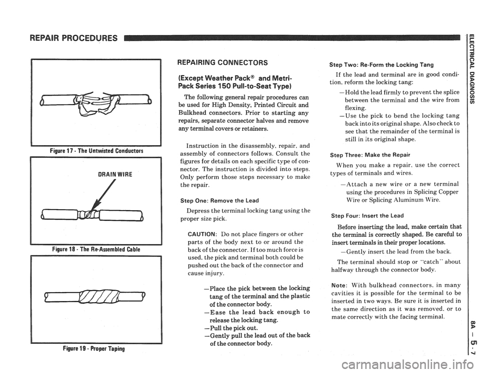
Figure 18 - The ReAssernbled Gable
Figure
19 - Proper Taping
REPAIRING CONNECTORS
(Except
mather Pack@ and Metri-
Pack Series 150 Pull-to-Seat Type)
The following general repair procedures can
be used for Nigh Density, Printed Circuit and
Bulkhead connectors. Prior to starting any
repairs, separate connector halves and remove
any terminal covers or retainers.
Instruction in the disassembly, repair, and
assembly of connectors follows. Consult the
figures for details on each specific type of con-
nector. The instruction is divided into steps.
Only perform those steps necessary to make
the repair.
Step One: Remove the Lead
Depress the terminal locking tang using the
proper size pick.
CAUTION: Do not place fingers or other
parts of the body next to or around the
back of the connector. If too much force is
used, the pick and terminal both could be
pushed out the back of the connector and
cause injury.
-Place the pick between the locking
tang of the terminal and the plastic
of the connector body.
-Ease the lead back enough to
release the locking tang.
-Pull the pick out.
-Gently pull the lead out of the back
of the connector body. Step
Two: Re-Form the Locking Tang
If the lead and terminal are in good condi-
tion, reform the locking tang:
-Hold the lead firmly to prevent the splice
between the terminal and the wire from
flexing.
-Use the pick to bend the locking tang
back into its original shape. Also check to
see that the remainder of the terminal is
still in its original shape.
Step Three: Make the Repair
When you make a repair, use the correct
types of terminals and wires.
-Attach a new wire or a new terminal
using the procedures in Splicing Copper
Wire or Splicing Aluminum Wire.
Step Four: Insert the Lead
Before inserting the lead, make certain that
the terminal is correctly shaped. Be
careful to
insert terminals in their proper locations.
-Gently insert the lead from the back.
The terminal should stop or
"catch" about
halfway through the connector body.
Note: With bulkhead connectors. in many
cavities it is possible for the terminal to be
inserted in two ways. Be sure it is inserted in
the same direction as it was removed. or to
mate correctly with the facing terminal.
Page 1209 of 1825
POWER DISTRIBUTION
CIRCUIT OPERATION
Electrical power for the car is provided by the
Generator when the engine is running. The
schematic diagram shows how each circuit gets
its power. For more details about the Gener-
ator, and connections to the Battery and
Starter, see Starter and Charging System, Sec-
tion
8A-30.
The car's Power Distribution System con-
sists of Fusible Links, Fuses, Circuit Breakers,
the Light Switch and the Ignition Switch. Fusi-
ble Links are short pieces of wire to which they
supply power. They are covered with a special
high-temperature insulation. When conducting
a high current, the Fusible Link will melt and
stop current flow. They are designed to protect
the car's electrical system from electrical
shorts where it is not protected by the Circuit
Breakers and Fuses. See Fuse Block Details
and Light Switch Details for complete wiring to
the first component in each circuit.
The Ignition Switch has six positions, five of
which have detents. The BULB TEST position
is after the RUN position and just before the
START position. BULB TEST does not have a
detent. As shown in the schematic, circuits
which are supplied from the Ignition Switch are
On (Hot) for different switch positions. Indi-
vidual schematics show their fuses supplied
from headings such as "Not In Run. "The head-
ing corresponds to the Ignition Switch position
in which power is On.
Page 1397 of 1825
WARNINGS AND ALARMS: CHIMES
GlRGUlT OPERATION
The Warnings and Alarms System sounds a
chime to bring attention to one or more of
several conditions. These conditions are:
1) the
lights are on and the Ignition Switch is not in
RUN, BULB TEST, or START;
2) the Igni-
tion key is in the Ignition Switch when the
driver's door is open; and
3) the seatbelt is un-
buckled when the Ignition Switch is in RUN,
BULB TEST, or START.
Voltage is applied at all times through the
STOP
HAZ Fuse to terminal B, to power the
solid state Audio Alarm Assembly.
IGNITION KEY VVARNING
Voltage is applied to the Audio Alarm As-
sembly by the STOP HAZ Fuse. Whenever the
key is in the Ignition Switch and the Ignition
Switch is in LOCK, OFF, or ACCY with the
driver's door open, terminal C of the module is
grounded. This sounds the alarm.
LIGHTS-ON WARNING
When the Light Switch is in HEAD or
PARK, voltage
is applied to the Audio Alarm
Assembly. When the Ignition Switch
is in
RUN, BULB TEST, or START, voltage is
applied through the Gages Fuse to the module.
These two voltages are sensed and the alarm is
not sounded.
When the Ignition Switch is not in RUN,
BULB TEST, or START, the Gages Fuse loses
voltage. The Audio Alarm Assembly senses the
change. If voltage is still available from the
Light Switch, the Lights-On Warning alarm
will sound. The alarm can be turned off by
turning the Light Switch to the OFF setting.
The module no longer senses voltage from the
Light Switch, so the alarm does not sound.
SEATBELT WARNING
With the Ignition Switch in RUN, BULB
TEST, or START, voltage is applied through
the Gages Fuse to the Audio Alarm Assembly.
With the driver's
seatbelt unbuckled, terminal
H of the module is grounded through the Seat-
belt Switch. The FASTEN BELTS Indicator
always goes on for about
5 seconds when the
Ignition Switch is set to RUN, BULB TEST,
or START. The Fasten Belts Chime, however,
only sounds if the
seatbelt is unbuckled and
the Ignition Switch
is in RUN, BULB TEST
or START
Page 1411 of 1825
(Continued from previous page)
If the Speedometer reads correctly, refer to
Vehicle Speed Sensor, Section
8A-33 for fur-
ther diagnosis.
If the Speedometer reads incorrectly, check
LT GRN (537) wire and the Instrument Clus-
ter Printed Circuit for opens. Replace the
Speedometer Assembly if the wire and
Printed Circuit are good (see Section
8C).
O: UPSHIFT INDICATOR WIRE TEST
Disconnect ECM connector C207. Put the Igni-
tion Switch in RUN and measure the voltage at
terminal
H (see section 8A-21 or 22).
If battery voltage is present, see section
6E
for ECM diagnosis.
If battery voltage is not present, check the
TANIBLK (422) wire for an open or short to
Ground.
CIRCUIT OPERATION
The operation of an indicator is explained in
the operation of the circuit it is apart of. See the
circuit referred to for a complete description of
that indicator and the other components that
work with it. Only the gages and indicators that
do not appear in other schematics are described
in this section.
Tachometer
The Tachometer displays engine speed in
rpm. Voltage pulses are taken from the Ignition
System and sent to the Tachometer. Solid State
circuits process these pulses into a signal that
drives the pointer of the meter. The Tachometer
responds to the frequency of the voltage pulses.
These pulses increase with engine speed.
Fuel Gage
The pointer of the Fuel Gage is moved by the
magnetic field of two coils. The coils are at right
angles to each other. Battery voltage is applied
to the E coil and the circuit divides at the
opposite end of this coil. One path continues to
ground through the F coil. Another goes to
ground through the variable resistor of the Fuel
Gage Sender Unit.
When the tank is low, the resistance of the
Fuel Gage Sender is low. A large flow of current
passes through the E coil and the Fuel Gage
Sender resistor. This moves the pointer
towards E on the scale. When the tank is
full,
the sender resistance is high. More current
flows through the F coil, moving the pointer
toward F on the scale.
With two coils operating the pointer, the Fuel
Gage is not affected by changes in the voltage
of the system.
011 Pressure Gage
The engine oil pressure is displayed by the Oil
Pressure Gage. The pointer of the gage is
moved by two coils, and its operation is similar
to that of the Fuel Gage. The
Oil Pressure Sender is connected to the
junction of the two coils.
It has low resistance
when the oil pressure is low, and 90 ohms
resistance when the oil pressure is high. This
changing resistance changes the current flow
through the coils. The magnetic fields of the
coils move the pointer to indicate high or low
coolant temperature.
Voltmeter
The Voltmeter measures the electrical sys-
tem voltage with the Ignition Switch in RUN,
BULB TEST, or START. With the engine
stopped, the Voltmeter indicates battery condi-
tion. With the engine
running, the Voltmeter
indicates Charging System operation.
Coolant Temperature Gage
The Coolant Temperature Gage is also oper-
ated by two coils. Battery voltage is applied to
both coils. One is grounded directly
and the
other is grounded through the Coolant Tem-
perature Sender. This has 54 ohms resistance at
260
OF, 130 "C (hot coolant) and its resistance
becomes greater at lower temperatures. It is
appr~ximately 1284 ohms at 100 OF (40 '6). This
causes the current through the sender and one
coil to vary as the coolant temperature charges
and this moves the pointer.
Page 1476 of 1825
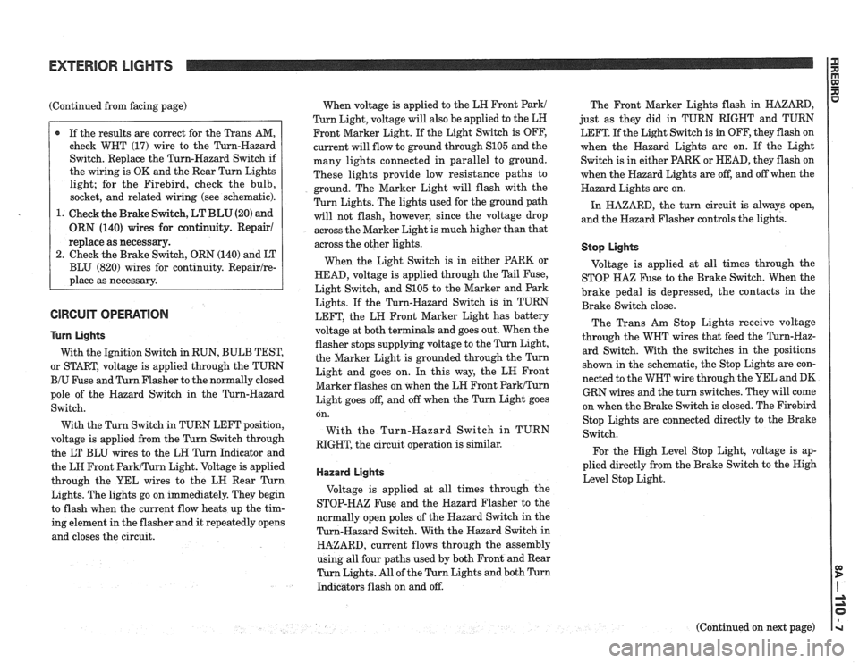
(Continued from facing page)
@ If the results are correct for the Trans AM,
check WHT (17) wire to the Turn-Hazard
Switch. Replace the Turn-Hazard Switch if
the wiring is OK and the Rear Turn Lights
light; for the Firebird, check the bulb,
socket, and related wiring (see schematic).
1. Check the Brake Switch,
LT BLU (20) and
ORN (140) wires for continuity. Repair1
replace as necessary.
2. Check the Brake Switch, ORN (140) and LT
BLU (820) wires for continuity.
Repairlre-
place as necessary.
GlRGUlT OPERATION
Turn Lights
With the Ignition Switch in RUN, BULB TEST,
or START, voltage is applied through the TURN
BIU Fuse and Turn Flasher to the normally closed
pole of the Hazard Switch in the Turn-Hazard
Switch.
With the Turn Switch in TURN LEFT position,
voltage is applied from the Turn Switch through
the LT BLU wires to the LH Turn Indicator and
the LH Front
ParWTurn Light. Voltage is applied
through the YEL wires to the LH Rear Turn
Lights. The lights go on immediately. They begin
to flash when the current flow heats up the tim-
ing element in the flasher and it repeatedly opens
and closes the circuit. When
voltage is applied to the LH Front
Park1
Turn Light, voltage will also be applied to the LH
Front Marker Light. If the Light Switch is OFF,
current will flow to ground through
S105 and the
many lights connected in parallel to ground.
These lights provide low resistance paths to
ground. The Marker Light will flash with the
Turn Lights. The lights used for the ground path
will not flash, however, since the voltage drop
across the Marker Light is much higher than that
across the other lights.
When the Light Switch is in either PARK or
HEAD, voltage is applied through the Tail Fuse,
Light Switch, and
S105 to the Marker and Park
Lights. If the Turn-Hazard Switch is in TURN
LEFT, the LH Front Marker Light has battery
voltage at both terminals and goes out. When the
flasher stops supplying voltage to the Turn Light,
the Marker Light is grounded through the Turn
Light and goes on. In this way, the LN Front
Marker flashes on when the LH Front
ParkITurn
Light goes off, and off when the Turn Light goes The
Front Marker Lights flash in HAZARD,
just as they did in TURN RIGHT and TURN
LEFT. If the Light Switch is in OFF, they flash on
when the Hazard Lights are on. If the Light
Switch is in either PARK or HEAD, they flash on
when the Hazard Lights are off, and off when the
Hazard Lights are on.
In HAZARD, the turn circuit is always open,
and the Hazard Flasher controls the lights.
Stop Lights
Voltage is applied at all times through the
STOP
HA% Fuse to the Brake Switch. When the
brake pedal is depressed, the contacts in the
Brake Switch close.
The Trans Am Stop Lights receive voltage
through the WHT wires that feed the Turn-Haz-
ard Switch. With the switches in the positions
shown in the schematic, the Stop Lights are con-
nected to the WHT wire through the YEL and DK
GRN wires and the turn switches. They will come
on when the Brake Switch is closed. The
Firebird on.
With
RIGHT, Stop
Lights are connected directly to the Brake
the Turn-Hazard Switch in TURN
Switch.
the circuit operation is similar.
For the High Level Stop Light, voltage is ap-
plied directly from the Brake Switch to the Nigh
Hazard Lights Level Stop Light.
Voltage is applied at all times through the
STOP-HAZ Fuse and the Hazard Flasher to the
normally open poles of the Hazard Switch in the
Turn-Hazard Switch. With the Hazard Switch in
HAZARD, current flows through the assembly
using all four paths used by both Front and Rear
Turn Lights. All of the Turn Lights and both Turn
Indicators flash on and off.
(Continued on next page)
Page 1485 of 1825
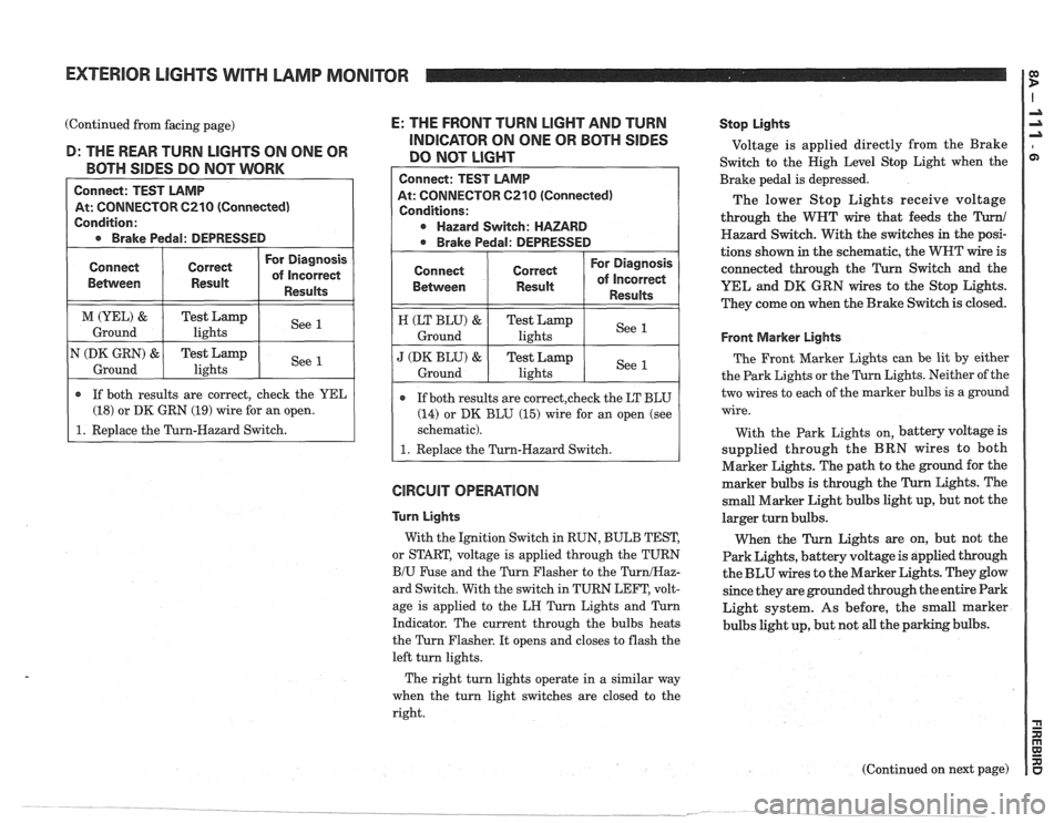
EXTERIOR LIGHTS WITH LAMP MONITOR
(Continued from facing page) E: THE FRONT TURN LIGHT AND TURN -- - INDICATOR ON ONE OR BOTH SIDES D: THE REAR TURN LIGHTS ON ONE OR
DO NOT LIGHT BOTH SIDES DO NOT WORK
Connect: TEST LAMP
At: CONNECTOR C210 (Connected)
Condition:
* Brake Pedal: DEPRESSED
GlRGUlT OPERATION
Connect
Bemeen
M (YEL) &
Ground
N
(DK GRN) &
Ground
Connect: TEST LAMP
At: CONNECTOR
6210 (Connected)
Conditions:
Hazard Switch: HAZARD
* Brake Pedal: DEPRESSED
Turn Lights
With the Ignition Switch in RUN, BULB TEST,
or START, voltage is applied through the TURN
B/U Fuse and the Turn Flasher to the TurnIHaz-
ard Switch. With the switch in TURN LEFT, volt-
age is applied to the
LH Turn Lights and Turn
Indicator. The current through the bulbs heats
the Turn Flasher. It opens and closes to flash the
left turn lights.
Connect
Between
H (LT BLU) &
Ground
J (DK BLU) &
Ground
Stop Lights
Voltage is applied directly from the Brake
Switch to the High Level Stop Light when the
Brake pedal is depressed.
The lower Stop Lights receive voltage
through the WHT wire that feeds the
Turn1
Hazard Switch. With the switches in the posi-
tions shown in the schematic, the WNT wire is
connected through the
Turn Switch and the
YEL and
DK GRN wires to the Stop Lights.
They come on when the Brake Switch is closed.
r If both results are correct, check the YEL
(18) or DK GRN (19) wire for an open.
1. Replace the Turn-Hazard Switch.
Correct
Result
Test Lamp lights
Test Lamp
lights
Front Marker Lights
The Front Marker Lights can be lit by either
the Park Lights or the Turn Lights. Neither of the
two wires to each of the marker bulbs is a ground
wire.
For Diagnosis
of Incorrect
Results
See 1
See 1
If both results are correct,check the LT BLU
(14) or DK BLU (15) wire for an open (see
schematic).
1. Replace the Turn-Hazard Switch.
Correct
Result
Test Lamp lights
Test
Lamp
lights
With the Park Lights on, battery voltage is
supplied through the BRN wires to both
Marker Lights. The path to the ground for the
marker bulbs is through the Turn Lights. The
small Marker Light bulbs light up, but not the
larger turn bulbs.
When the Turn Lights are on, but not the
Park Lights, battery voltage is applied through
the BLU wires to the Marker Lights. They glow
since they are grounded through the entire Park
Light system. As before, the small marker
bulbs light up, but not all the parking bulbs.
For Diagnosis
of Incorrect
Results
See 1
See 1
The right turn lights operate in a similar way
when the turn light switches are closed to the
right.
(Continued on next page)
Page 1600 of 1825
LIGHTING SYSTEMS AND HORNS 8B-I
SECTION 8B
NG SYSTEMS AND HORNS
CONTENTS
........................... GENERAL DESCRIPTION 8B-1
Exterior Lights
....................... ................... Back-up Lights .. 8B- 1
Center High-Mounted Stoplight .................... 8B-1
Exterior Light Monitor .................................. 8B-1
............................ .................... Fog Lights .. 8B-1
Front Parking/Turn Signal Lights ................ 8B-2
............................... Hazard Flashers .. ........ 8B-2 .................................................... Headlights 8B-2
License Plate Lights ..................................... 8B-2
Light Switch ............................................... 8B-2
............... Rear Tail/Stop/Turn Signal Lights 8B-2
Sidemarker Lights ........................................ 8B-2
Turn Signals .......................................... 8B-2
......................... Underhood Light ... ........ 8B-2
Horns .......................................................... 8B-3
....................................... ON-CAR SERVICE 8B-3
Exterior Lights
............................................. Back-up Lights 8B-3
Center High-Mounted Stoplight .................... 8B-3
Fog Lights .................................................... 8B-4
Front Parking/Turn Signal Lights ................ 8B-4
Hazard Flasher .............................................. 8B-5
....................................................... Headlights 8B-5
License Plate Lights ..................................... 8B-7
............... Rear Tail/Stop/Turn Signal Lights 8B-8
.......................................... Sidemarker Lights 8B-8
................... ............... Turn Signal Flasher .. 8B-9
......................................... Underhood Light 8B-9
Horns ................................................................. 8B-9
REPLACEMENT BULB
.................................... SPECIFICATIONS 8B- 10
The following information, previously shown in this section,
has been moved to the sections shown.
Back-up Lights Switch
............................. ... ............................................................................ 7
................................................................................................................................. Fuse Block 8A
Ignition Switch ........................................................................................................................... 3B
Interior Lights
................................................................................................................... 8A, 8C
Neutral Start Switch ..................................................................................................................... 7
Parking Brake Warning Switch
......................... ... .................................................................... 5
........................................................................ Seat Belt, Key and Headlight Warning Alarm 8A
Stoplight Switch .......................... .. ............................................................................................... 5
Windshield
Wipers/Washers .................................................................................................... 8E
GENERAL DESCRIPTION
The exterior lighting system includes the
headlights (and headlight motors to raise or lower the
headlights), front
parkinghurn signal lights, front
cornering lights, fog lights, rear
tail/stop/turn signal
lights, back-up lights, license plate lights, center
high-mounted stoplight, and the underhood light; it
also includes all associated wiring, controls and related
hardware for these lights.
BACK-UP LIGHTS - The back-up lights are
next to the rear license plate. They will come on when
the transmission is shifted to Reverse. On cars with an
automatic transmission, the back-up lights are
activated by the neutral start switch. On cars with a
manual transmission, they are activated by a separate
back-up light switch on the transmission. For more
information, see Section 7.
CENTER HIGH-MOUNTED STOPLIGHT-
The center high-mounted stoplight, in the center of the
rear spoiler, will come on whenever the brake pedal is
pushed down. The light is powered separately from the rear
tail/stop/turn signal
lights through a separate
circuit in the stoplight switch (see Section
8A).
EXTERIOR LIGHT MONITOR - The Driver
Information Center, on cars so equipped, also monitors
certain front and rear lights. When a bulb burns out,
the message
"FRONT LAMP" or "REAR LAMP"
will appear in the DIC display, and a light will come
on to indicate which bulb has burned out. For more
information, see Section
8A.
FOG LIGHTS -The fog light switches are to the
left of the steering column on the edge of the
instrument panel. To use the fog lights, first turn on the
headlights or parking lights. Then, push the middle
switch (with the fog light symbol) to turn on the fog
lights. Push the left
("OFF") switch to turn off the fog
lights.
The fog lights should not be used as a substitute
for the headlights.
Switching to high-beam headlights will turn off
the fog lights; switching back to low-beams will turn
the fog lights on again.
Page 1667 of 1825
VACUUM SUPPLY
Tht vacuum to operate the Cruise Control servo
can come from: manifold vacuum connected straight
to the servo, from manifold through a vacuum storage
tank, or straight from a vacuum pump. For specific
vacuum routing, see On-Car Service.
ELECTRICAL AND VACUUM RELEASE
SWITCHES
These switches are used to disengage the cruise
control system. An electrical release switch mounted
on the brake pedal bracket (and clutch pedal bracket
on cars equipped with manual transaxle) disengages
the system electrically when the brake (or clutch) pedal is
depressed. This is done by interrupting the flow of
current to the controller. A vacuum release valve
mounted on the brake pedal bracket vents the trapped
vacuum in the servo to atmosphere when the brake
pedal is depressed, allowing the servo unit to more
quickly return the throttle to idle position. This is done
by routing a separate hose directly to the servo from
the normally closed vacuum switch. These two types
of switches will also sometimes be combined with stop
light switch, TCC switch, or other switches. For
specific usage and adjustment of these switches, see
On-Car Service.
ELECTRICAL HARNESS
For specific wiring and connector locations, see
Section
8A-34, 'Cruise Control'.
Improper operation can be caused by one or a
CRUISE SYSTEM SURGES t combination of mechanical, electrical and vacuum The servo and throttle linkages should operate problems. In resolving any cruise system operating
problem, first make a visual inspection. Check the freely
and smoothly. This linkage should be
system to ensure there are no bare, broken, or adjusted
as described in the On-Car Service
disconnected wires or any pinched, damaged,
-or portion of this section.
disconnected vacuum hoses. The servo and throttle
e Check hose routing for pinches, leaks or
linkage should operate freely and smoothly. The servo restrictions.
(See vacuum schematics in the
linkage should be adjusted as described in the On-Car On-Car
Service portion of this section).
Service portion of this section. See
Section
8A-34, 'Cruise Control'.
CRUISE SET SPEED HIGH OR LOW
Since any problem in this system is either
vacuum, mechanical, or electrical, the technician
should perform a few initial checks before turning to
Section
8A. This can be done by first eliminating a
vacuum or mechanical problem by starting the engine
and using finger to feel for source vacuum at the servo,
and by visual inspection of vacuum release valve,
throttle linkage, vacuum hoses, etc. If preliminary
inspection reveals no solution and the system is
inoperative, use the diagnostic information in Section
8A-34, 'Cruise Control'.
Several versions of a quick check instrument
similar to tool 5-34185 are available. This quick check
instrument is installed in place of the controller and
determines which part of the system has a problem.
Instructions on the operation of the instrument will be
provided with the unit. Check vacuum hoses for
proper routing,
restrictions or leaks. Adjust or replace as
required. (See vacuum schematics in the On-Car
Service portion of this section.)
e Check servo linkage for excess slack and adjust
as described in the On-Car Service portion of this
section.
s If no system problem is noted, replace the
electronic controller (module).
EXCESSIVE CRUISE SPEED LOSS ON HILLS
e Check hoses for vacuum leaks. (See vacuum
schematics in the On-Car Service portion of this
section).
e Determine if check valve is functional (where
applicable).
CRUISE TAP-UP & TAP-DOWN
If all other functions of cruise control are working
except "tap-up" and "tap-down" the controller
(module) is at fault.