1988 PONTIAC FIERO stop start
[x] Cancel search: stop startPage 1784 of 1825
SEATS - F STYLE 9H-1
SEC"IC"0N 9H
SEATS
NOTICE: Lap belt to floor pan and shoulder belt to roof panel or quarter panel fasteners are important
attaching parts in that they could affect the performance of vital parts and systems, and/or could result in major
repair expense. They must be replaced with one of the same part number or with an equivalent part if replacement
becomes necessary. Do not use a replacement part of lesser quality or substitute design. Torque values must be
used as specified during reassembly to assure proper retention of these parts.
CONTENTS
Restraint Systems ........................................... 9H- 1
Lap and Shoulder Belts
............................... 9H-1
Comfort Lock Operational Checks
and Requirements
.................................... 9H- 1
Front Seat Shoulder Belt Retractor
............ 9H-2
Child Seat
...................................................... 9H-2
............................... .................. -.rant Seats .. 9H-5
Mead Restraint
............................................. 9H-5
Reclining
Seatback ................................... 9H-6
Front
Seatback ........................................... 9H-7
Inertia Lock Check
...................................... 9H-7
............................... Manual Recliner Check 9H-7
........................... Seat Torque Specifications 9H-8
Manual Seat
- Diagnosis Chart ................... 9H-8
..................... Power Seat - Diagnosis Chart 9H-9
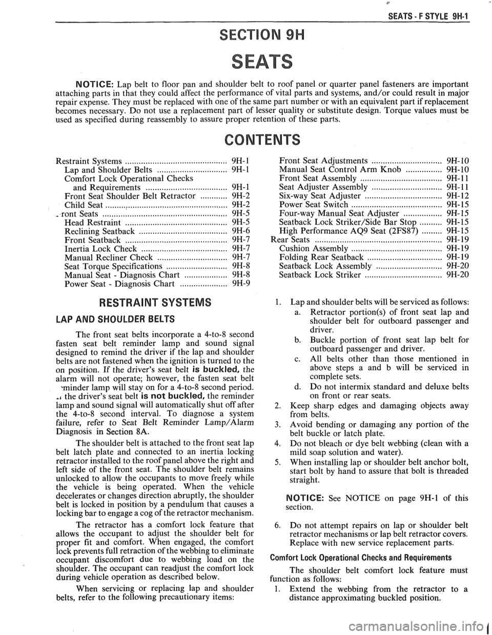
RESTRAINT SYSTEMS
LAP
AND SHOULDER BELTS
The front seat belts incorporate a 4-to-8 second
fasten seat belt reminder lamp and sound signal
designed to remind the driver if the lap and shoulder
belts are not fastened when the ignition is turned to the
on position. If the driver's seat belt
is buckled, the
alarm will not operate; however, the fasten seat belt
xminder lamp will stay on for a 4-to-8 second period.
,, the driver's seat belt is not buckled, the reminder
lamp and sound signal will automatically shut off after
the 4-to-8 second interval. To diagnose a system
failure, refer to Seat Belt Reminder
Lamp/Alarm
Diagnosis in Section 8A.
The shoulder belt is attached to the front seat lap
belt latch plate and connected to an inertia locking
retractor installed to the roof panel above the right and
left side of the front seat. The shoulder belt remains
unlocked to allow the occupants to move freely while
the vehicle is being operated. When the vehicle
decelerates or changes direction abruptly, the shoulder
belt is locked in position by a pendulum that causes a
locking bar to engage a cog of the retractor mechanism.
The retractor has a comfort lock feature that
allows the occupant to adjust the shoulder belt for
proper fit and comfort. When engaged, the comfort
lock prevents full retraction of the webbing to eliminate
occupant discomfort due to webbing load on the
shoulder. The occupant can readjust the comfort lock
during vehicle operation as described below.
When servicing or replacing lap and shoulder
belts, refer to the following precautionary items: Front
Seat Adjustments
............................... 9H- 10
Manual Seat Control Arm Knob
................ 9H-10
Front Seat Assembly
.................................... 9H- 1 1
Seat Adjuster Assembly ............................. 9H-11
Six-way Seat Adjuster .................................. 9H- 12
Power Seat Switch
........................................ 9H-15
Four-way Manual Seat Adjuster
................. 9H-15
Seatback Lock Striker/Side Bar Stop .......... 9H-15
High Performance AQ9 Seat
(2FS87) ......... 9H-15
................. .................................... Rear Seats ... 9H- 19
........................................ Cushion Assembly 9H- 19
................................ Folding Rear Seatback 9H- 19
........................... Seatback Lock Assembly 9H-20
.................................. Seatback Lock Striker 9H-20
1. Lap and shoulder belts will be serviced as follows:
a. Retractor
portion(s) of
front seat lap and
shoulder belt for outboard passenger and
driver.
b. Buckle portion of front seat lap belt for
outboard passenger and driver.
c. All belts other than those mentioned in
above steps a and b will be serviced in
complete sets.
d. Do not intermix standard and deluxe belts
on front or rear seats.
2. Keep sharp edges and damaging objects away
from belts.
3. Avoid bending or damaging any portion of the
belt buckle or latch plate.
4. Do not bleach or dye belt webbing (clean with a
mild soap solution and water).
5. When installing lap or shoulder belt anchor bolt,
start bolt by hand to assure that bolt is threaded
straight.
NOTICE: See NOTICE on page 9H-1 of this
section.
6. Do not attempt repairs on lap or shoulder belt
retractor mechanisms or lap belt retractor covers.
Replace with new service replacement parts.
Comfort Lock Operational Checks and Requirements
The shoulder belt comfort lock feature must
function as follows:
1. Extend the webbing from the retractor to a
distance approximating buckled position.
Page 1798 of 1825
SEATS - F STYLE 9H-15
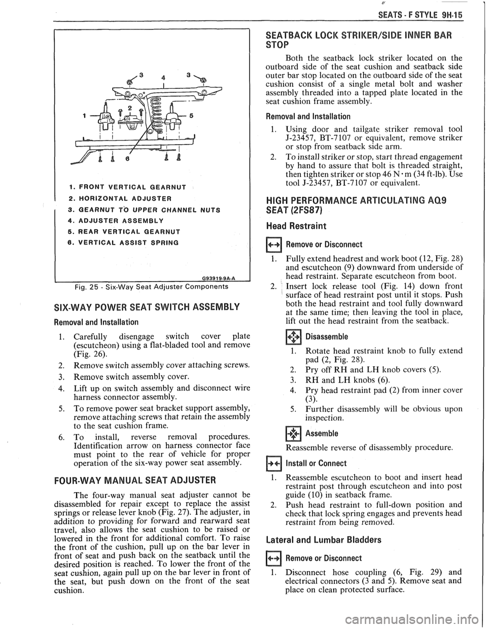
I 1. FRONT VERTICAL GEARNUT I 1 2. HORIZONTAL ADJUSTER
1 3. QEARNUT T'O UPPER CHANNEL NUTS
1 4. ADJUSTER ASSEMBLY I 5. REAR VERTICAL GEARNUT
6. VERTICAL ASSIST SPRING
Fig. 25 - Six-Way Seat Adjuster Components
SIX-WAY POWER SEAT SWITCH ASSEMBLY
Removal and Installation
1. Carefully disengage switch cover plate
(escutcheon)
using a flat-bladed tool and remove
(Fig. 26).
2. Remove
switch assembly cover attaching screws.
3. Remove switch assembly cover.
4. Lift
up on switch assembly and disconnect wire
harness connector assembly.
5. To
remove power seat bracket support assembly,
remove attaching screws that retain the assembly
to the seat cushion frame.
6. To install, reverse removal procedures.
Identification arrow on harness connector face
must point to the rear of vehicle for proper
operation of the six-way power seat assembly.
FOUR-WAY MANUAL SEAT ADJUSTER
The four-way manual seat adjuster cannot be
disassembled for repair except to replace the assist
springs or release lever knob (Fig.
27). The adjuster, in
addition to providing for forward and rearward seat
travel, also allows the seat cushion to be raised or
lowered in the front for additional comfort. To raise
the front of the cushion, pull up on the bar lever in
front of seat and push back on the
seatback until the
desired position is reached. To lower the front of the
seat cushion, again pull up on the bar lever in front of
the seat, but push down on the front of the seat
cushion.
SEATBACK LOCK %%RIMEW/SIDE INNER BAR
STOP
Both the seatback lock striker located on the
outboard side of the seat cushion and
seatback side
outer bar stop located on the outboard side of the seat
cushion consist of a single metal bolt and washer
assembly threaded into a tapped plate located in the
seat cushion frame assembly.
Removal and Installation
1.
Using door and tailgate striker removal tool
J-23457, BT-7107 or equivalent, remove striker
or stop from
seatback side arm.
2. To install striker or stop, start thread engagement
by hand to assure that bolt is threaded straight,
then tighten striker or stop 46
N.m (34 ft-lb). Use
tool J-23457, BT-7107 or equivalent.
HIGH PERFORMANCE ARTICULATING AQ9
SEAT (2FS87)
Head Restraint
Remove or Disconnect
1.
Fully extend headrest and work boot (12, Fig. 28)
and escutcheon
(9) downward from underside of
head restraint. Separate escutcheon from boot.
2. Insert lock release tool (Fig. 14) down front
surface of head restraint post until it stops. Push
both the head restraint and tool fully downward
at the same time;
then leaving the tool in place,
lift out the head restraint from the seatback.
Disassemble
1. Rotate head restraint knob to fully extend
pad
(2, Fig. 28).
2. Pry
off RH and LH knob covers
(5).
3. RH and LH knobs (6).
4. Pry
head restraint pad (2) from inner cover
(3).
5. Further disassembly will be obvious upon
inspection.
+'+ Assemble [I]
Reassemble reverse of disassembly procedure.
Install or Connect
1. Reassemble escutcheon to boot and insert head
restraint post through escutcheon and into post
guide (10) in
seatback frame.
2. Push head restraint to full-down position and
check that lock spring engages and prevents head
restraint from being removed.
Lateral and Lumbar Bladders
Remove or Disconnect
1. Disconnect hose coupling (6, Fig. 29) and
electrical connectors (3 and 5). Remove seat and
place on clean protected surface.
Page 1817 of 1825
2 - CHASSIS INDEX
Backup Lamp Switch (Circuit) .......... 8A- 1 12. 7A 1-5
Backup Lights
..................................................... 8B-1
...................................................... Battery Section 6D 1
............................ Battery Specification Chart 6D 1-7
.................................... Body Identification ... .... OA- 1
Borg Warner Rear Axle .......................... Section 4B1
...................................................... Blower Motor 1A-14
Blower Switch
.................................................... 1 A- 13
Booster Assembly
............................................. 5D2-2
Brakes
- General ......................................... Section 5
Adjustment
.................................................... 5C3-4
Booster Assembly
. Tandem
Diaphragm
................... .... ..................... 5D2- 1
................................................ Components 5C3- 1
Diagnosis and Inspection
................................. 5-3
Disc Brake Caliper Assembly
.................................................... 3548 Series 5B6-1
Drum Brake Assembly ........................ Section 5C3
General Description
.......................................... 5-2
On-Car Service
.................................................... 5-7
Specifications & Special Tools ......................... .5 F. 1
...................................................... Unit Repair 5A3- 1
.......................................... Warning System 8A-4 1-0
............ Brake Pedal Mounting .. ......................... 5-1 7
Bulb Usage Chart
............................................ 8B-10
............................................ Bumpers Section 2B,3 D.6
Bumper Energy Absorbing Units
.................... 2B-2
Bench Testing
................................................ 2B-3
........................................ Damage/Leakage 2B-3
................................ Removal After Collision 2B-2
............................................. Fascia Rub Strips .2 B. 1
.................................................... Front Bumper 2B-2
Assembly
........................................................ 2B-4
Energy Absorber
........................................... 2B-4
............................................................. Fascia .2 B. 1
On-Vehicle Service
...................................... 2B-4
Rear Bumper
.................................... .... ............ 2B-2
........................................................ Assembly 2B-5
Energy Absorber
............................................ 2B-4
............. .................... Fascia Molding Strip .. 2B-5 ........................................... Service Procedures .2 B. 1
.................................................. Specifications 2B-5
C
Caliper Assembly . Disc Brake
.............................................. 3000/3 100 Series 5B 1-2
3548 Series
...................................................... 5B6-2
Caliper Overhaul
....................... 3000/3 100 Series .. ............... 5B 1-4
3548 Series
.................................................... 5B6-5
Caster and Camber Adjustment
........................ 3A- 1
............................................. Catalytic Converter 6F-2
Center High-Mounted Stoplight
....................... ... 8B- 1
Charging System
...................... 8A.30.7, Section 6D3
Chassis Electrical
.................................... Section 8B
Center High Mounted Stoplight
...................... 8B-1 ................................. Exterior Light Monitor .8 B. 1
................................................................ Chimes 8A-77
................................ Cigar Lighter (Circuit) 8A- 1
14-0
.............................. Circuit Breaker Details Section 8A
Power ACC Circuit Breaker .... 8A- 10.1.10.3.10.5.
11-3
.... Window Circuit Breaker 8A~10~1,10~3.10~5.1 1.4
Clutch
........................................................ Section 7C
......................................... General Description .7 C. 1 ........................................................... Diagnosis 7C-2 Bleeding
Hydraulic Clutch System
................. .7 C.2
Preliminary Checks ..................................... ... 7C-2
On-Vehicle Service
........................................... 7C-5
Clutch Hydraulic System
.................................. 7C-5
Clutch Pedal ...................................................... 7C-6
Pilot Bearing
..................................................... 7C-6
Pressure Plate and Disc
.................................... 7C-6
Special Tools
......................... ....... ................ 7C-8
Specifications
................................................... 7C-8
Coil Springs and Insulators .............................. 3D-1
Component Fluid Capacities
................................ OB-6
Component Location Views
........................ 8A-201-0
Composite Master Cylinder
................... Section 5A3
Compression Test
.................. .. ............................. 6-5
Condenser Mounting
....................................... 1B 1-24
Connectors
.................................................... 8A-202-0
Coolant Fan Temperature Switch
...................... 8A-3 1
Cooling and Radiator
................................ Section 6B
Cooling System Capacities
................................. OB-6
Cooling System Diagnosis
.................................... 6B-3
Cranking System
...................................... Section 6P*
Diagnosis ..................................................... 6~2
General Description ................................ 6D2- 1
Cranking System
........................................ 6D2- 1
Solenoid
................................................... 6D2- 1
Starter Motor ......................................... 6D2-1
On-Vehcile Service
...................................... 6D2-4
Specifications
............................................ 6D2- 1
Starter
........................................................ 6D2-4
Unit Repair
............................................ 6D2-6- 11
Service Procedures
...................................... 6D2-3
Cruise Control
.............................. 8A-34-0, Section 9B
Diagnosis
............................................................ 9B-4
Cruise Set Speed High or Low
.................... 9B-4
Cruise System Surges
.................................. 9B-4
Cruise Tap-Up and Tap-Down
...................... 9B-4
Excessive Cruise Speed Loss on
Hills
........................................................... 9B-4
General Description
........................................ 9B-1
Electrical and Vacuum Release
Switches
...................................................... 9B-4
Electrical Harness
.......................................... 9B-A
Electronic Controller (Module) .................... 9B .
Off/On/Resume/Accel Switch
Operation
.................................................. .91 B-
Servo Unit
.................................................... 9B-2
Set/Coast Button Switch .............................. 9B-1
................................................ Speed Sensors 9B-3
Vacuum Supply
............................................ 9B-4
On-Car Service
.................................................. 9B-6
................................ Cruise Release Switches 9B-6
.......................................... Servo Mounting 9B-10
Vacuum Harness and Cable Routing
VIN
E ................................. .. .................. 9B,7
.................................................... VIN F, 8 9B-9
....................................................... VIN S 9B-8
........................ Vacuum Tank - VIN S,F,E, 9B-10
.............................. Cruise Control (Circuit) 8A-34-0
D
......................................... Defogger (Circuit) $A-6 1-0
..................... ...... Defroster Duct Assembly ... .812 C-
Diagnosis
Air Conditioning
- General ........................... 1B-5
.................... Automatic Transmission - General 7A
Automatic Transmission
- ................ HD-700-R4-2
Page 1821 of 1825
6- CHASSIS INDEX
Upper Air Outlet Deflectors ...................... 8C-12
Interior Lights ............................................. 8A- 1 17-0
Intermediate Shaft (Steering Column)
.............. 3B5-3
J
Jump Starting .................................................... 6D 1-4
Junction Block
((2238) ................................. 8A-202-2
L
Lamp Monitoring ......................................... 8A- 1 1 1-0
License Plate Lights .............................................. 8B-2
Light Switch
.................................................... 8A- 12-0
Lighting Systems and Horns
...................... Section 8B
General Description ......................................... .8 B- 1
Exterior Lights
............................................ 8B- 1
Horns ....................... .. ................................. 8B-3
On-Car Service
.................................................. 8B-3
Exterior Lights 8B-3
Horns
.............................................................. 8B-9
Replacement Bulb Specifications .................... 8B-10
Lights (Exterior) Electrical Diagnosis
Back-up
...................................................... 8A- 1 12-0
Fog ............................................... 8A- 100.3,10 3.0
Front
Marker/Park/Hazard .................... 8A-110-0
Hazard with Lamp Monitor .................... 8A-103-0
Headlights .................................................. 8A- 100-0
High Level Stop
..................................... 8A-110-0
License .................................................. .8A.110.3, 4
Rear Marker
........................................... .8 A. 1 10.3, 4
Stop ........................................................... 8A-110-1
Tail ......................................................... .8 A. 1 10.3, 4
Tail with Monitor
................ .... ........... 8A- 1 1 1-2
Turn
......................................................... 8A- 1 10-0
Lights (Interior) Electrical
Diagnosis Cargo Compartment
............................. 8A- 1 14- 1
Courtesy
................................................. 8A- 1 14-0
Dome
.................................. .. ...................... 8A- 1 14-0
Glove Box .................................................. 8A- 1 14-0
Lights Dimming
...................................... 8A- 1 17-0
Reading
...................................................... 8A- 1 14-0
Lower Heater Outlet
........................................ 1A-14
Lubrication Fitting Locations .............................. OB-6
M
Maintenance and Lubrication .................... Section OB
Manual Transmission
. 5 Speed 77 mm .... Section 7B
Diagnosis
........... .. ............................................ 7B-2
On-Vehicle Service
.......................................... 7B-3
Repairs
................................... .... .................... 7B- 12
Special Tools
................................................. 7B-20
. Specifications .............................................. 7B 19
Maintenance Items
................................................ OB-2
Master Cylinder
........................................ Section 5A3
General Description
...................................... ..5A 3.2
On-car Sevice
................................................ 5A3-2
Unit Repair ..................................................... .5A 3.2
Master Cylinder Overhaul
......................... .5A 3.2
Master Cylinder Reservoir
......................... .5A 3.3
Metric Fasteners
................................................ OA- 1
Metric-English Conversion Table ..................... .O A. 10
Miscellaneous Accessories
........................ Section 9G
Diagnosis
.......................................................... 9G-2
Dash/Console Mounted Accessory
Switches
.................................................... 9G-4 Electric
Rear Window Defogger
................ 9G-2
Power Remote Control
Rearview
......................... Mirror ...................... .. 9G-2
Rally Gages
................................................. 9G-2
Tachometer
.................................................. 9G-2
..................................... General Description 9G-4
Electric Glare Control Monitor
.................. 9G-4
Electric Rear Window Defogger
................ 9G-2
Power Remote Control
Rearview
Mirror ..................................................... 9G-2
Rally Gages
................................................. 9G-1
Tachometer
................................................. 9G-1
Trip Odometer
............................................ 9G-1
............................................. On-Car Service 9G-4
Power Remote Control Mirror
.................... 9G-4
Rally Gages. Tach
..................................... 9G-4
Rear Window Defogger
.............................. 9G-4
Mirrors..Power ............................................ 8A- 141-0
Automatic
Day/Night ............................. 8A- 143-0
..................................... Defogger. Mirror 8A-61-0
.......................................... Model Identification OA-'
Muffler ................................................................. 6Fi
N
Neutral Start and Back-Up Lamp
Switch
...................................... ..
0
On-Vehicle Service
Air Conditioning
.................................... ... . 1B-20
Automatic Transmission
............................... .7A 1.3
Battery
........................................................ 6D1-5
................................ ......................... Brakes ... 5-7
Bumpers
......................................................... 2B-4
Charging System
.............................. ... ........... 6D3-2
Chassis Sheet Metal
.......................................... 2C-7
Clutch
................................................................ 7C-5
Cranking System
............................................ 6D2-4
Cruise Control ............................................... 9B-6
Disc Brake Caliper Assembly,
3000/3 100 Series .......................................... 5BliC
Disc Brake Caliper Assembly,
3548 Series
................................................... 5B6-3
Drum Brake Assembly .................................... 5C3-1
Engine (V-6) .................................................... 6A2-7
Engine (V-8) ................................................ -6A3-5
Engine Cooling ....................................... .. .... 6B- 14
Front Suspension
........................................... 3C-1
Horns and Lighting System .............................. 8B-3
Ignition System
.............................................. 6D4-5
Instrument Panel, Gages and
Console
.......................................................... 8C-4
Lighting System and Horns
.......................... .... 8B-3
Miscellaneous Accessories
.......................... .... 9G-4
Power Head Assembly
. Tandem
Diaphragm
................................................. 5D-2
Power Steering Gear and Pump
.................... 3B7-3
Propeller Shaft
............................................. 4A-1
.......................... Radio Systems and Antennas 9A-9
Rear Axle
.......................................................... 4B-8
Rear Axle (Borg Warner)
........................... ... 4B 1-7
Steering Linkage ............................................. 3B6-2
........................ Steering Wheels and Columns 3B5-2
Wheel Alignment
......................................... 3A-2
Windshield Wiper
- Washer System ................ 8E-3
Page 1823 of 1825
8- CHASSIS INDEX
Recommended Fluids and Lubricants ................ OB-6
Relay Rod
......................................................... 3B6-2
Remote Mirror Control
...... See Body Service Section
5H.1. 15
Repair Procedures
.......................................... 88-50
S
........................................ Scheduled Maintenance OB- 1
Seats (Power) ....................................... Lumbar Support 8A- 145-0
............................. Sequential Fuel Injection 6E3-C2- 1
Service Engine Soon Light
.................................... 8C-3
Sheet Metal and Grille
................................ Section 2C
......................................... General Description .2 C. 1
........................................... Service Procedures .2 C. 1
................................................................. Hood .2 C. 1
...................................................... Hood Hinge 2C-2
Hood Latch and Cable
...................................... 2C-2
Paint
.............................................. Color Matching 2C-5
................................................ Identification -32-6
Interior Plastic Parts ...................................... 2C-6
................................................ Shock Absorbers 3D-
1
Shoe and Lining Assembly
. Brake
............................................ 3000/3 100 Series 5B1-3
3548 Series ...................................................... 5B6-4
Side Marker Lights
.............................................. 8B-2
........ Speakers See 8A- 150-0 & Body
Manual Section
6H- 1
.................... Spark Plug Gap .. .................. 6E3-13-3
................................ Speaker and Speaker Grille 9A-9
Special Tools
............................................ Air Conditioning 1 B-3 5
Air Conditioning Compressor
................................................. Overhaul 1D1-21
........................ Automatic Transaxle AT-700-R4-64
................................................................ Brakes SF-1
Clutch ................................................................ 7C-8
................................................................ Rear 4B1-20
....................................... Rear (Borg Warner) 4B-20
........................... Driveability and Emissions .6 E. 17
................................................ Engine Cooling 6B- 14
Power Steering Pump
& Gear ...................... 3B7-17
............................................... Propeller Shaft .4 A. 12
Steering Wheels and Columns
.......................... 5-35
Specifications Automatic Transmission Unit
............................................ Repair AT-700-R4-59
..................................................... Battery 6D 1-7
................................................................ Brakes 5F-1
Bumpers
......................................................... 2B-5
Charging System
................ .. ................... 6D3-3
.............................................................. Clutch .7 (2.8
....................................... Cranking System 6D2- 1 1
Driveability and Emissions ............................ 6E-23
................................................ Engine (V-6) ..6A 2.26
Engine (V-8) .................................................. 683-28
........................................ Front Suspension 3C- 10
Power Steering Gear and Pump
.................. 3B7-18 ............................................. Propeller Shaft .4 A. 12 ........................................................ Rear Axle 4B-19 ............................ Rear Axle (Borg Warner) 4B 1- 19
Rear Suspension
.............................................. 3D-9
.......................................... Replacement Bulbs 8Br 10 .............................................. Steering Linkage 3B6-6
Steering Wheels and Columns
...................... 3B5-35
........................................ Wheel Alignments 3A-4
....................................................... Speedometer 8C-2
........................................ Speedometer (Removal) 8C-5
...................................................... Speed Sensors 8C-1
Starter ........................................ Section 6D2. 8A-30-0
............................................. Starter (Circuit) 8A-30-0
Steering Linkage ...................................... Section 3B6
....................................... General Description 3B6-1
........................ Maintenance and Adjustments 3B6-1
................................................ On-Car Service 3B6-2
..................................................... Idler Arm 3B6-4
................................................ Pitman Arm 3B6-5
.................................................... Relay Rod 3B6-3
Tie Rods
...................................................... 3B6-2
.................................................. Specifications 3B6-6
Steering, Suspension, Tires and
Wheels Diagnosis
............................................................. 3-1
Steering Wheels and Columns
............................ 3B5-1
..................................... General Information 3B5- 1
Maintenance and Adjustments
...................... 3B5-'
On-Car Service .............................. .. ........... 3B5
Checking for Accident Damage
.................. 3B5-5
Intermediate Shaft ............... .. .................... 3B5-3
Park Lock Cable .......................................... 3B5-4
Standard Column
............................. Automatic Transaxle 3B5-13
Manual Transaxle ................................. 3B5- 19
Tilt Column
.............................. Automatic Transaxle 3B5-27
.................................. Manual Transaxle 3B5-19
Unit Repair Intermediate Shaft
...................................................... Assembly 3B5-6
................................................. Special Tools 3B5-35
Torque Specifications
.................................... 3B5-35
............................................. Starting System 8A-30-0
........................................ Strut Assembly (Front) 3C-4
.................................... ..... Symbols Chart ... 8A-3-0
T
.......................................................... Tachometer 9G-1
Tail/Stop/Turn Signal/Lights .......................... 8B-2
Temperature Cable
.............................................. 112 A-
Temperature Warning Light ................................ 8C-3
Theft Deterrent (Circuit)
.............................. 8A-133-0
Tie Rods
.............................................................. 3B6-2
Tires and Wheels
........................................ Section 3E
Diagnosis
.................................................. Section 3
General Information
......................................... 3E-1
................................................... Metric Tires 3E-2
....................................... Replacement Tires .31 E-
.................................................... Tire Placard 3E-2
........................................................... Wheels 3E-2
Maintenance and Adjustments
.......................... 3E-2
.......................... Aluminum Wheel Cleaning 3E-9
............................. ......... Inflation of Tires .. 3E-3
........................................ Tire Chain Usage 3E-4
.................................................. Tire Rotation 3E-3
.............................................. Wheel Repair 3E-2
...................................... Wheel Studs/Nuts 3E-3
........................................... Service Operations 3E-4
........................ Aluminum Wheel Cleaning 3E-9
.................................... Balance Precautions 3E-7
............................ Balancing Tire and Wheel 3E-7
.............................................. Compact Spare 3E-6
........................ Correcting Nonuniform Tires 3E-8