1988 PONTIAC FIERO stop start
[x] Cancel search: stop startPage 937 of 1825
NEGATIVE BACKPRESSURE EGR VALVE
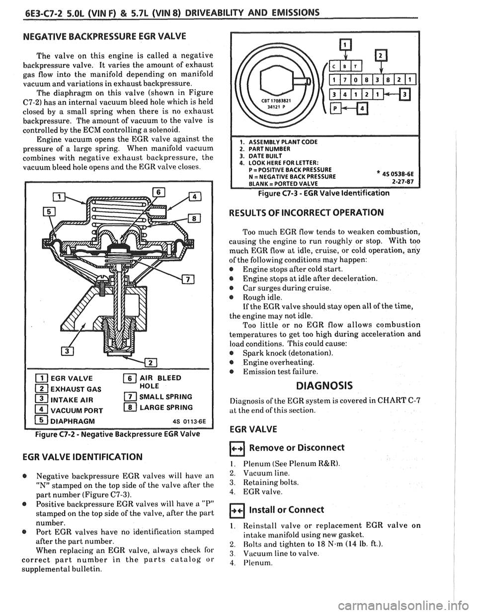
The valve on this engine is called a negative
backpressure valve. It varies the amount of exhaust
gas flow into the manifold depending on manifold
vacuum and variations in exhaust backpressure.
The diaphragm on this valve (shown in Figure
C7-2) has an internal vacuum bleed hole which is held
closed by
a small spring when there is no exhaust
backpressure. The amount of vacuum to the valve is
controlled by the
ECM controlling a solenoid.
Engine vacuum opens the EGR valve against the
pressure of
a large spring. When manifold vacuum
combines with negative exhaust backpressure, the
vacuum bleed hole opens and the EGR valve closes.
EGR VALVE AIR BLEED
EXHAUST GAS HOLE
INTAKE AIR SMALL
SPRING
VACUUM PORT LARGE
SPRING
Figure C7-2 - Negative Backpressure EGR Valve
EGR VALVE IDENTIFICATION
@ Negative backpressure EGR valves will have an
"N" stamped on the top side of the valve after the
part number (Figure
C7-3).
@ Positive backpressure EGR valves will have a "P"
stamped on the top side of the valve, after the part
number.
@ Port EGR valves have no identification stamped
after the part number.
When replacing an
EGIE valve, always check for
correct part number in the parts catalog or
supplemental bulletin.
Figure C7-3 - EGR Valve Identification
RESULTS OF INCORRECT OPERATION
Too much EGR flow tends to weaken combustion,
causing the engine to run roughly or stop. With too
much EGR flow at idle, cruise, or cold operation,
aliy
of the following conditions may happen:
@ Engine stops after cold start.
@ Engine stops at idle after deceleration.
@ Car surges during cruise.
@ Rough idle.
If the EGR valve should stay open all of the time,
the engine may not idle.
Too little or no EGR flow allows combustion
temperatures to get too high during acceleration and
load conditions. This could cause:
@ Spark knock (detonation).
@ Engine overheating.
@ Emission test failure.
DIAGNOSIS
Diagnosis of the EGR system is covered in CHART C-7
at the end of this section.
EGR VALVE
Remove or Disconnect
1. Plenum (See Plenum R&R).
2. Vacuum line.
3. Retaining bolts.
4. EGR valve.
Install or Connect
1. Reinstall valve or replacement EGR valve on
intake manifold using new gasket.
2. Bolts and tighten to 18 N.m (14 Ib. ft.).
3. Vacuum line to valve.
4. I'lenum.
Page 965 of 1825
6E-4 DRIVEABILITY AND EMISSIONS - FUEL INJECnON
and ohms. You should understand what happens in a
circuit with an open or a shorted wire. You should be
able to read and understand a wiring diagram. A
short to ground
is referred to as a ground to
distinguish it from a short between wires.
Use of Circuit Testing Tools
You should know how to use a test light, how to
connect and use
a tachometer, and how to use jumper
wires to by-pass components to test circuits. Care
should be taken to not deform the terminal when
testing.
Use of Digital Volt-Ohm Meter (DVM)
You should be familiar with the digital volt-ohm
Meter, particularly essential tool J-29125-A,
J34029A
or equivalent. You should be able to measure voltage,
resistance, and current, and know how to use the
meter correctly.
The digital volt-ohm meter is covered in the
"Special
ToolsJ'portion of this section.
DIAGNOSTIC INFORMATION
The electronic control module (ECM) is equipped
with a self-diagnosis system which detects system
failure and aids the technician by identifying the
circuit at fault via a trouble code. Below is
information about the way the ECM displays a
problem and how this corresponds to a trouble code in
the ECM. The ECM can also indicate an "Open Loop"
or "Closed Loop" mode.
"'Service Engine Soonw Light
This light is on the instrument panel, and has two
functions:
@ It is used to tell the driver that a problem has
occurred, and that the vehicle should be taken for
service as soon as reasonably possible.
@ It is used by the technician to read out "Trouble
CodesJ' to help diagnose system problems.
As a bulb and system check, the light will come
"ON" with the key "ON" and the engine not running.
When the engine is started, the light will turn "OFF".
If the light remains "ONJ', the self-diagnostic system
has detected a problem. If the problem goes away, the
light will go out in most cases after 10 seconds, but a
Trouble Code will remain stored in the ECM.
Intermittent "Service Engine Soon" Light
The diagnostic charts in Section "A" are set up to
check whether or not a stored trouble code is
"intermittent" or "hard". An
"intermittent" code is one which does not
always reset when the code setting parameters are
met, or is not present while you are working on the
vehicle. This is often caused by
a loose connection.
The facing page will contain diagnostic aids to help in
detecting
intermittents.
A "hard" code is one which is present when you
are working on the vehicle and the condition still
exists while working on the vehicle. The chart with
the stored trouble code number will lead you to the
cause of the problem.
Trouble Codes
The engine control module (ECM) is really a
computer. It uses sensors to look at many engine
operating conditions. It has
a memory and it knows
what certain sensor readings should be under certain
conditions. These conditions are described on the
facing page of each Trouble Code chart. If a sensor
reading is not what the ECM thinks it should be, the
ECM will turn "ON" the "Service Engine Soon" light
on the instrument panel, and will store a Trouble Code
in the memory. The Trouble Code tells which circuit
the trouble is in. A circuit consists of a sensor (such as
coolant temperature), the wiring and connectors to it,
and the ECM.
i
To get a Trouble Code out of the ECM, we use the
assembly line diagnostic link (ALDL) connector.
!
ALDL Connector I
I
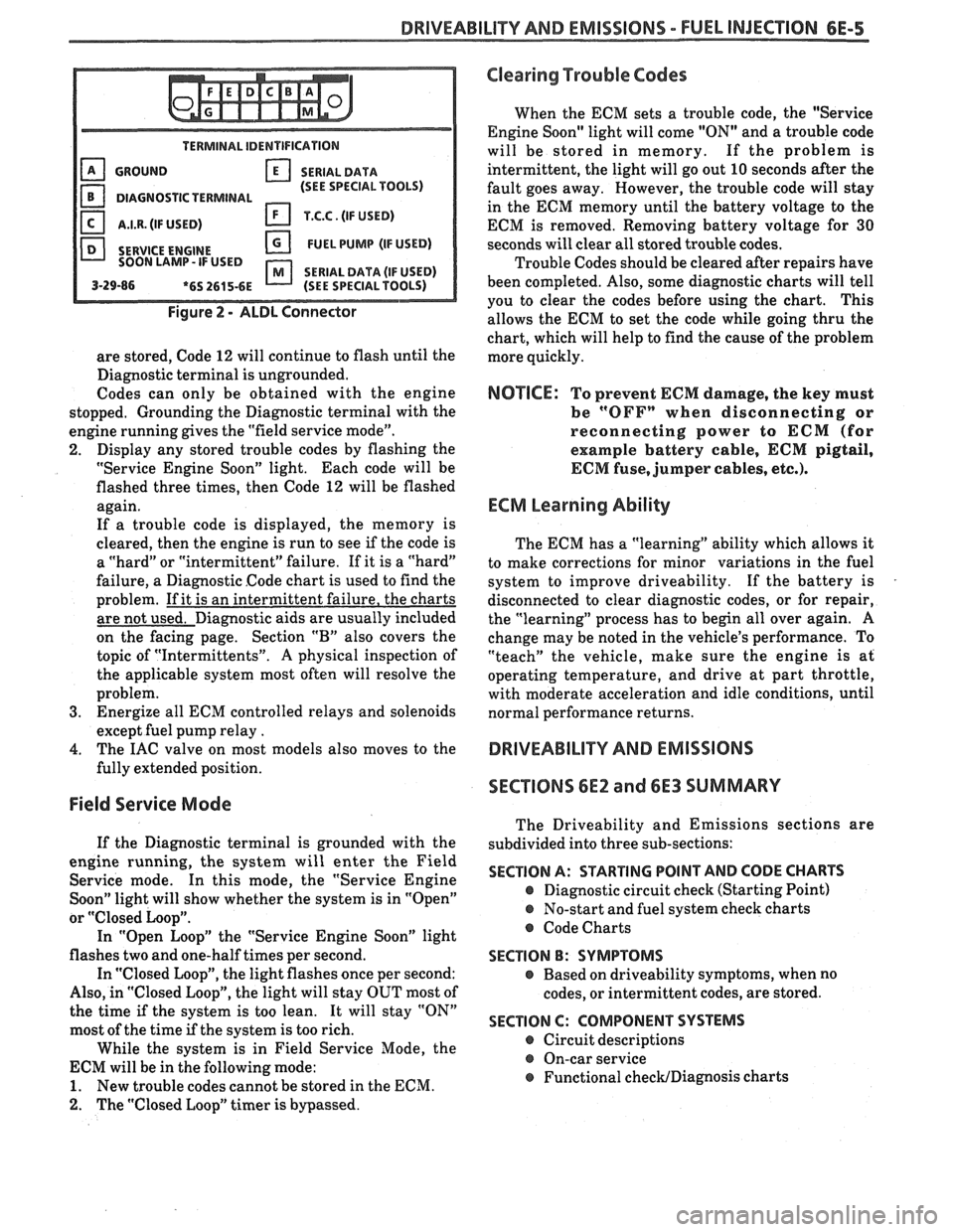
The assembly line diagnostic link (ALDL) is a
diagnostic connector located in the passenger
compartment (Figure 2). It has terminals which are
used in the assembly plant to check that the engine is
operating properly before it leaves the plant.
Terminal "B" is the Diagnostic terminal, and it can be
connected to terminal
"A", or ground, to enter the
Diagnostic mode, or the Field Service Mode.
The ALDL connector is also used by "ScanJ' tools to
read information from the ECM via the Serial Data
Line. Serial Data information
is used extensively
throughout the manual.
Diagnostic Mode
1
If the Diagnostic terminal is grounded with the
ignition "ON" and the engine stopped, the system will
enter the Diagnostic Mode. In this mode the ECM
will:
1. Display a Code 12 by flashing the "Service Engine
Soon" light (indicating the system is operating). A
Code 12 consists of one flash, followed by a short
pause, then two flashes in quick succession. This
code will be flashed three times. If no other codes
Page 966 of 1825
DRIVEABILITY AND EMISSIONS - FUEL INJECTION 6E-5
TERMINAL IDENTIFICATION
GROUND SERIALDATA
(SEE SPECIAL TOOLS)
DIAGNOSTIC TERMINAL
I.I.R. (IF USED) T.C.C. (IF USED)
SERVICE
ENGINE FUEL PUMP (IF USED)
SOON LAMP- IF USED
SERIAL DATA (IF USED) 3-29-86 *6S 2615-6E (SEE SPECIAL TOOLS)
Figure 2 - ALDL Connector
are stored, Code 12 will continue to flash until the
Diagnostic terminal is ungrounded.
Codes can only be obtained with the engine
stopped. Grounding the Diagnostic terminal with the
engine running gives the "field service mode".
2. Display any stored trouble codes by flashing the
"Service Engine Soon" light. Each code will be
flashed three times, then Code
12 will be flashed
again.
If a trouble code is displayed, the memory is
cleared, then the engine is run to see
if the code is
a "hard" or "intermittent" failure. If it is a "hard"
failure, a Diagnostic Code chart is used to find the
problem. If it is an intermittent failure, the charts
are not used. Diagnostic aids are usually included
on the facing page. Section
"B" also covers the
topic of "Intermittents".
A physical inspection of
the applicable system most often will resolve the
problem.
3. Energize all ECM controlled relays and solenoids
except fuel pump relay
.
4. The IAC valve on most models also moves to the
fully extended position.
Field Service Mode
If the Diagnostic terminal is grounded with the
engine running, the system will enter the Field
Service mode. In this mode, the "Service Engine
Soon" light will show whether the system is in "Open"
or
"Closed Loop".
In "Open Loop" the "Service Engine Soon" light
flashes two and one-half times per second.
In "Closed Loop", the light flashes once per second:
Also, in "Closed Loop", the light will stay OUT most of
the time
if the system is too lean. It will stay "ON"
most of the time if the system is too rich.
While the system is in Field Service Mode, the
ECM will be in the following mode:
1. New trouble codes cannot be stored in the ECM.
2. The "Closed Loop" timer is bypassed.
Clearing Trouble Codes
When the ECM sets a trouble code, the "Service
Engine Soon" light will come "ON" and a trouble code
will be stored in memory. If the problem is
intermittent, the light will go out
10 seconds after the
fault goes away. However, the trouble code will stay
in the ECM memory until the battery voltage to the
ECM is removed. Removing battery voltage for
30
seconds will clear all stored trouble codes.
Trouble Codes should be cleared after repairs have
been completed. Also, some diagnostic charts will tell
you to clear the codes before using the chart. This
allows the ECM to set the code while going thru the
chart, which will help to find the cause of the problem
more quickly.
NOTICE: To prevent ECM damage, the key must
be
"OFFn when disconnecting or
reconnecting power to
ECM (for
example battery cable,
ECM pigtail,
ECM fuse, jumper cables, etc.).
ECM Learning Ability
The ECM has a "learning" ability which allows it
to make corrections for minor variations in the fuel
system to improve driveability. If the battery is
disconnected to clear diagnostic codes, or for repair,
the "learning" process has to begin all over again.
A
change may be noted in the vehicle's performance. To
"teach" the vehicle, make sure the engine is at
operating temperature, and drive at part throttle,
with moderate acceleration and idle conditions, until
normal performance returns.
DRIVEABILITY AND EMISSIONS
SECTIONS
6E2 and 6E3 SUMMARY
The Driveability and Emissions sections are
subdivided into three sub-sections:
SECTION A: STARTING POINT AND CODE CHARTS
@ Diagnostic circuit check (Starting Point)
@ No-start and fuel system check charts
@ Code Charts
SECTION B: SYMPTOMS
e Based on driveability symptoms, when no
codes, or intermittent codes, are stored.
SECTION C: COMPONENT SYSTEMS
@ Circuit descriptions
@ On-car service
@ Functional checWDiagnosis charts
Page 969 of 1825
6E-8 DRIVEABILITY AND EMISSIONS - FUEL INJECTION
Throttle Position Sensor (TPO) Coolant Q~erature
Values read will be the voltage as seen by the Engine
temperature is displayed in Celsius
ECM. The voltage should be the TPS specification degrees.
After the engine is started, temperature
with the throttle closed and go up to about 5 volts should
rise steadily to about
85-95" C, then stabilize
with throttle wide open
(WOT). when the thermostat opens.
Throttle Angle
Displayed, in percent, is the amount the throttle is
open. 0% is closed throttle, 100% is wide open throttle.
Oxygen (Of) Sensor
The reading will be read out in millivolts (mv)
with a range from 1 to 999 mv. If the reading is
consistently below 350 (350 mv), the fuel system
is
running lean as seen by the ECM; and if the reading is
consistently above 550 (550 mv), the system is
running rich.
In this position, information is used for assembly
verification only. PROM ID is useful only when the
vehicle
is equipped with the original ECM and PROM
or Mem-Cal.
Reading displays engine rpm. It is often useful if
extra reference pulses are suspected. A sudden high
rpm indication while at a steady throttle would
indicate electrical interference
(EMI) in the reference
circuit. This interference
is usually caused by ECM
wires too close to ignition secondary wires or an open
distributor ground circuit.
Displayed is vehicle speed, useful in checking TCC
application speed or speedometer accuracy.
MAF
This displays the amount of air passing the Mass
Air Flow
(MAF) sensor, in grams per second. It is
useful when comparing the airflow between a problem
vehicle and a known good one. Normal readings at
idle are about
4 to 8 grams. If a MAF code is set, this
reading will display the ECM default value.
This display should be the same as MAF when
there are no failures in the MAP sensor circuit. When
an MAF code is set, however, this value will not
change, and will indicate the
grn/sec that the failure
has detected.
Manifold Air Temperature (MAT) Sensor
This displays temperature of the intake manifold
air. It should read close to ambient air temperature
when the engine is cold, and rise as underhood and
engine temperatures increase.
Manifold Absolute Pressure (MAP)
The MAP sensor produces a low signal voltage
when manifold pressure is low (high vacuum) and a
high voltage when the pressure is high (low vacuum).
With the ignition "ON" and the engine stopped,
I
the manifold pressure is equal to atmospheric
pressure, and the signal voltage will be high. This 1
information is used by the ECM as an indication of
vehicle altitude and is referred to as BARO.
Comparison of this
BARO reading with a known good
vehicle with the same sensor is a good way to check
accuracy of a "suspect" sensor
*. Readings should be
the same
+ .4 volt. I
* A MAP sensor has a colored plastic insert visible I I
in the connector cavity. Sensors with the same insert I
color are identical in calibration. The harness I
I
electrical connector color also should be the same as 1 the sensor insert color.
I Vacuum (Differential Pressure) Sensor
The vacuum sensor produces a low signal voltage
when manifold vacuum is low, and a high voltage
when the vacuum is high.
With the ignition "ON" and the engine stopped,
there is no vacuum, so the voltage is low (under
1
volt). With the engine idling the vacuum is high so the
voltage is high (over
3 volts).
A vacuum sensor has a colored plastic insert
visible in the connector cavity. Sensors with the same
insert color are identical in calibration. The harness
electrical connector color also should be the same as
the sensor insert color.
This displays barometric pressure. The ECM uses
this information to adjust for altitude and pressure.
This value will vary depending on barometric
pressure and altitude. Some vehicles use a dedicated
bar0 sensor, while others take a MAP reading before
the engine is started, and at various times during
engine operation.
Page 971 of 1825
6E-18 DRIVEABILITY AND EMISSIONS - FUEL INJECRON
CCP (Carbon Canister Purge)
This displays "ON" when the canister purge
solenoid is commanding purge. Some display duty
cycle from
0-1008.
2nd Gear
This displays the state of the 2nd gear switch.
Yes=2nd gear applied. It remains applied in 3rd and
4th gears.
3rd Gear
This displays the state of the 3rd gear switch.
Yes= 3rd gear applied. It remains applied in 4th gear.
4th Gear
This displays the state of the 4th gear switch.
Yes
= 4th gear applied.
Fan Request
State of the AJC fan control switch is displayed. It
should read "yes" when fan is requested. Some
engines may display the state of the 2nd fan, if used.
Power Steering Pressure Switch
This reading displays the state of switch, and may
vary with the tool used, and the type of switch
installed on the vehicle. The important thing is that
the reading changes state (switches) when the
steering is moved against the stops.
Electronic Control Module (ECM)
This section describes the ECM and the
information sensors in the system. Figure
4 shows
the operating conditions which the ECM may sense
and the systems that the ECM may control. (See
specific engines to determine which are applicable
to
that engine.)
Fuel Control System
The ECM controls the aidfuel delivery to the
combustion chamber by controlling the fuel flow
through the
injector(s).
Electric Fuel Pump (In-tank)
The in-tank fuel pump is controlled by the ECM.
When ignition is turned "ON", the pump will run for 2
seconds, then stop unless the ECM is receiving
ignition pulses, as when cranking or running.
Evaporative Emission ControI
This system has a canister which stores fuel vapor
from the fuel tank. The fuel vapor is removed from the
canister and consumed in the normal combustion
process when the engine is running. This system is
used on all engines and may or may not be controlled
by the ECM.
ilectronic Spark Timing (EST)
This system is controlled by the ECM, which
controls spark advance (timing), and is used on all
engines.
SECTION B - DRIVEABILIW SYMPTOMS Electronic Spark
Control (ESC)
Always start with Section "A" "Diagnostic Circuit
Check" before proceeding to the driveability
symptoms or an emissions test failure. Section "A"
checks the ECM, which may cause the driveability
problem. A definition of each symptom is included.
This will then lead to the most probable causes of the
driveability problem.
SECTION C - COMPONENT SYSTEMS
There are many component systems that are used
to control fuel and emissions. Section
"C" introduces
each component system or control with a general
description, diagnosis, and on-vehicle service.
Each of the Section "C" diagnosis sections contain
information on how the "ScanJ' tool can be used for
diagnosing a particular component when a trouble
code has not been set. (example: Section
"Cl" under
diagnosis will explain how the "Scan" tool can be used
for diagnosis as well as what the normal readings
would be for the
ECM sensors.) This
system uses a knock sensor in connection
with the ECM to control spark timing, to allow the
engine to have maximum spark advance without
spark knock. This improves driveability and fuel
economy, but will retard spark
if detonation (spark
knock) is detected.
Air Injection Reaction (A.I.R.)
The system provides additional oxygen to the
exhaust gases to continue the combustion process.
The system also supplies additional air to the catalytic
converter under certain conditions. The A.I.R. system
is not on all engines.
Early Fuel Evaporation (EFE)
The EFE system heats the engine induction
system electrically or with exhaust gas during cold
Page 991 of 1825

700-R4-2 HYDRAULIC DIAGNOSIS
R - Reverse allows the vehicle to be operated in
a rearward direction.
N - Neutral allows the engine to be started and
operated without driving the vehicle. If necessary this
position may be selected if the engine must be restarted
with the vehicle moving.
D - Overdrive is used for all normal driving
conditions. It provides four gear ratios plus converter
clutch operation. Downshifts are available for safe
passing by depressing the accelerator.
D - Drive position is used for city traffic, hilly
terrain, and trailer towing. It provides three gear
ranges. Again, downshifts are available by depressing
the accelerator.
2 - Manual second is used to provide acceleration
and engine braking. This range may be selected at any
vehicle speed.
1 - Manual Lo is used to provide maximum
engine
brlking. This range may also be selected at any
vehicle speed.
DIAGNOSIS INFORMATION
ROAD TEST PROCEDURE
e Perform the road test following the sequence
given
e MPH (KPH) shift points will vary with actual
throttle position and driver habits
e Compare the results of the test with speed shift
chart information. Use these results with the
diagnosis information contained in this
Automatic Transmission Hydraulic Diagnosis
Section to evaluate the transmission.
e This test should only be performed when traffic
and road conditions permit
e Observe all traffic safety regulations
Drive and Reverse Engagement Shift Check
1. Start engine
2. Depress brake pedal
3. Move gear selector:
- "Park" (P) to "Reverse" (R)
- "Reverse" (R) to "Neutral"
(N) to "Drive" (D)
Gear selections should be immediate and
not harsh.
Upshifts and Torque Converter Clutch (TCC)
Apply (Figure
2)
With gear selector in "Overdrive" (D)
1. Accelerate using a steady increasing throttle
pressure
2. Note the shift speed point gear engagements for:
- 2nd gear
- 3rd gear
- Overdrive
3. Note the speed shift point for TCC apply. This
should occur while in third gear or overdrive. If
the apply is not noticed, refer to the Preliminary
Torque Converter Clutch Diagnosis information
contained in this section of the Service Manual.
Important
The torque converter clutch will not engage if
engine coolant has not reached a minimum
operating temperature of approximately 54°C
(1 30°F).
Part Throttle Downshift
At vehicle speeds of 40-55 MPH (64-88
KPH) quickly depressed the accelerator to
a half open position and observe:
- TCC releases
- Transmission downshift to 3rd gear
immediately
Full Throttle (Detent) Downshift
At vehicle speeds of 48-55 MPH (77-88
KPH) quickly depress the accelerator to a
wide open position and observe:
- TCC releases
- Transmission downshifts to 2nd gear
immediately
Manual Downshift
1. At vehicle speeds of 40-55 MPH (64 to 88 KPH)
release the accelerator pedal while moving the
gear selector to "Third" gear (D) and observe:
- TCC release
- Transmission downshift to 3rd gear should
be immediate
- Engine should slow vehicle down
2. Move gear selector to "Overdrive" and accelerate
to 40-45 MPH (64-72 KPH). Release the
accelerator pedal while moving the gear selector
to "Second" gear (2) and observe.
- TCC release
- Downshift to second gear should be
immediate
- Engine should slow vehicle down
3. Move gear selector to "Overdrive" (D) and
accelerate to 25 MPH (40 KPH). Release the
accelerator pedal while moving the gear selector
to "First" gear (1) and observe:
- TCC release
- Transmission downshift to 1st gear should
be immediate
- Engine should slow vehicle down
Coastdown Downshift
1. With the gear selector in "Overdrive" (D)
accelerate to 4th gear with TCC applied.
2. Release the accelerator pedal and lightly apply
the brakes to observe:
- TCC release
- Shift points for downshifts.
Manual Gear Range Selection
MANUAL THIRD (D)
1. With vehicle stopped, place gear selector in
"Third" (D) and accelerate to observe:
Page 1168 of 1825
INDEX
Page
................... Front Marker 110-0
...................... Frontpark 110-0
......................... Hazard 110-0
........ Hazard with Lamp Monitor 111-0
..................... Headlights 100-0
........................ Doors 102-0
............ With Lamp Monitor 103-0
................. Nigh Level Stop 110-0
................... License 110.3,11 0.4
Park
........................... 110-0
............... Rear Marker 110.3,11 0.4
stop
........................... 110-1
...................... Tail 110.3,11 0.4
................ Tail with Monitor 111-2
Turn ........................... 110-0
Lights (Interior)
.............. Cargo Compartment 114-1
....................... Courtesy 114-0
.......................... Dome 114-0
...................... Glove Box 114-0
................. Lights Dimming 117-0
........................ Reading 114-0
................ Light Switch Details 12-0
.................... Mirrors (Power) 141-0
Automatic
DayINight ............ 143-0
................. Power Distribution 10-0
Radio
...................... With UK3 150-0
With
UK3 and Subwoofer
..................... Amplifier 15 0-2
Without Subwoofer Amplifier and
with
UK3 ..................... 150-5 With
Subwoofer Amplifier and
without UK3
..................
.................. Repair Procedures
Seats (Power)
Lumbar Support
.................
Starter ............................
........................... Symbols
........... Theft Deterlent (Passkey)
......... Troubleshooting Procedures
.................. Hatch Pull-Down
..................... Hatch Release
............... Vehicle Speed Sensor
Warnings (Audible)
Chime
.........................
................... Windows (Power)
WiperIWasher
With Pulse .....................
................... Without Pulse
Page
Page 1186 of 1825
TROUBLESHOOTING TESTS m r rn 0
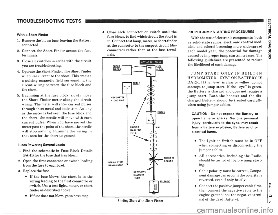
With a Short Finder
1. Remove the blown fuse, leaving the Battery
connected.
2. Connect the Short Finder across the fuse
terminals.
3. Close all switches in series with the circuit
you are troubleshooting.
4. Operate the Short Finder. The Short Finder
will pulse current to the short. This creates
a pulsing magnetic field surrounding the
circuit wiring between the fuse block and
the short.
5. Beginning at the fuse block. slowly move
the Short Finder meter along the circuit
wiring. The meter will show current pulses
through sheet
inetal and body trim. As long
as the meter is between the fuse block and
the short, the needle will move with each
current pulse. When you have
moved the
meter past the point of the short. the needle
will stop
moving. Examine the wiring in
that area for the short to ground.
Fuses Powering Several Loads
1. Find the schematic in Fuse Block Details
(8A-11) for the fuse that has blown.
2. Open the first connector or switch leading
from the fuse to each load.
3. Replace the fuse.
@ If the fuse blows, the short is in the
wiring leading to the first connector or
switch. Use a test light, meter, or short
finder as described above.
@ If fuse does not blow, go to next step.
4. Close each connector or switch until the PROPER JUMP STARTING PROCEDURES
fuse blows, to find which circuit the short is
With the use of electronic components (such
in. Connect test lamp, meter, or short finder
as solid-state radios, electronic control
mod- at the connector to the suspect circuit (dis- ules, and others) becoming more wide-spread
connected) rather than at the fuse termi- each model year, the potential for damage nals. caused by improper jump starts increases. The
SHORT FUSE FINDER - BLOCK -
MOVE METER
NEEDLE STOPS
MOVING HERE
NO PULSING
MAGNETIC
FIELD
Cb
SHORT TO
GROUND
w-
Finding Short With Short Finder
following guidelines are presented to reduce
the likelihood of such damage.
JUMP START ONLY IF BUILT-IN
HYDROMETER "EYE" ON BATTERY IS
DARK. If the "eye" is clear or yellow, do not
attempt to jump start. If the "eye" is green,
the Battery is charged and does not require a
jump start. Both the booster and the dis-
charged Battery should be treated carefully
when using jumper cables.
CAUTION: Do not expose the Battery to
open flame or sparks. Serious personal
injury, particularly
to the eyes, may result
from
a Battery explosion, Battery acid, or
electrical burns.
The Ignition Switch must be in OFF
when connecting or disconnecting the
jumper cables.
All accessories. including the Radio.
should be turned off before jump start-
ing.
Cable polarity must be correct. Compo-
nent damage can occur
if the polarity is
re~~ersed. even if only briefly.
a Connect the positive jumper cable first.
then connect the negative cable to the
engine ground (not the negative termi-
nal of the dead Battery).