1988 PONTIAC FIERO stop start
[x] Cancel search: stop startPage 349 of 1825
6-4 ENGINE GENERAL INFORMATION
Bent connecting rod.
HEAVY KNOCK H0"FVVI"F TORQUE APPLIED
Broken balancer, or pulley hub. Replace parts as e Exhaust system grounded. Reposition as
necessary. necessary.
Loose torque converter bolts. Flywheel
cracked.
e Excessive main bearing clearance. Replace as
Accessory belts too tight or nicked. Replace
necessary.
and/or tension to specs as necessary.
e Excessive rod bearing clearance. Replace as
necessary.
LIGHT KNOCK HOT
Detonation or spark knock. Check operation of e Loose torque converter bolts.
EST or ESC (See Section
6D or 6E). Check e Exhaust leak at manifold. Tighten bolts and/or
engine timing and fuel quality.
replace gasket.
8 Excessive rod bearing clearance. Replace
bearings as necessary.
KNOCKS ON INITIAL START-UP BUT ONLY LASTS A FEW SECONDS
Noisy mechanical fuel pump. Replace pump.
When the engine is stopped, some valves
will be open. Spring pressure against lifters
Improper oil viscosity. Install proper oil viscosity will
tend to bleed lifter down. Attempts to
for expected temperatures. See Owner's Manual. repair
should be made only if the problem
is consistent.
Hydraulic lifter bleed down. Clean, test and @ Excessive crankshaft end clearance. Replace
replace as necessary. crankshaft
thrust bearing.
@ Excessive front main bearing clearance. Replace
worn parts.
KNOCKS AT IDLE HOT
Loose or worn drive belts. Tension and/or @ Excessive piston pin clearance. Ream and install
replace as necessary. oversize pins. (VIN R and 2) or replace piston
A/C Compressor or generator bearing. Replace and
pin.
as necessary.
e Connecting rod alignment. Check and replace
rods as necessary.
Noisy mechanical fuel pump. Replace pump.
8 Insufficient piston to bore clearance. Hone bore
Valve train. Replace parts as necessary. and
fit new piston.
@ Loose crankshaft balancer. Torque and/or
Improper oil viscosity. Install proper viscosity oil
replace worn parts.
for expected temperature4 See Owner" e Piston pin offset to wrong side. Install correct
ENGINE OVERHEATS
Coolant system leak, oil cooler system leak, or
2. Belt slipping or damaged. Replace tensioner, or
coolant recovery system not operating. Check for belt, as required.
leaks and correct as required. Check coolant
3. Thermostat stuck closed. Check and replace if
recovery tank, hose and radiator cap.
required.
4. Electrical cooling fan operation. See the
ELECTRICAL TROUBLESHOOTING
MANUAL.
5. Head gasket leaking. Check and repair as
required.
Page 372 of 1825
2.8 LITER V-6 6A2-21
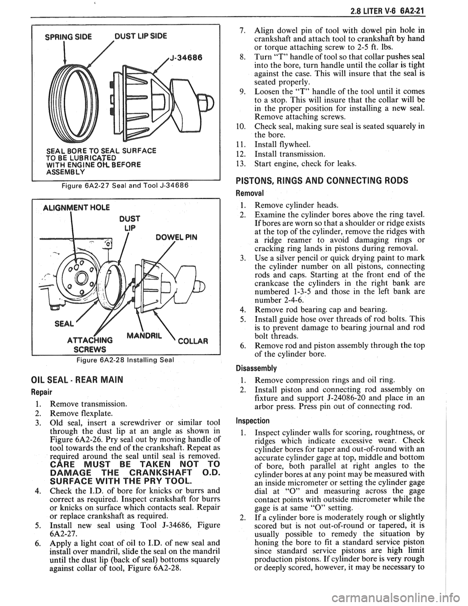
SEAL BORE TO SEAL SURFACE
TO BE LUBRICATED
WlTH ENGINE OK BEFORE I ASSEMBLY
Figure
6A2-27 Seal and Tool J-34686
ALIGNMENT HOLE
DUST
LIP
I SCREWS I
Figure 6A2-28 Installing Seal
OIL SEAL - REAR MAIN
Repair
1. Remove transmission.
2. Remove flexplate.
3. Old
seal, insert a screwdriver or similar tool
through the dust lip at an angle as shown in
Figure
6A2-26. Pry seal out by moving handle of
tool towards the end of the crankshaft. Repeat as
required around the seal until seal is removed.
CARE MUST BE TAKEN NOT TO
DAMAGE THE CRANKSHAFT O.D.
SURFACE
WlTH THE PRY TOOL.
4. Check
the I.D. of bore for knicks or burrs and
correct as required. Inspect crankshaft for burrs
or knicks on surface which contacts seal. Repair
or replace crankshaft as required.
5. Install new seal using Tool J-34686, Figure
6A2-27.
6. Apply a
light coat of oil to I.D. of new seal and
install over mandril, slide the seal on the mandril
until the dust lip (back of seal) bottoms squarely
against collar of tool, Figure
6A2-28.
7. Align dowel pin of tool with dowel pin hole in
crankshaft and attach tool to crankshaft by hand
or torque attaching screw to 2-5 ft. lbs.
8. Turn
"T" handle of tool so that collar pushes seal
into the bore, turn handle until the collar is tight
against the case. This will insure that the seal is
seated properly.
9. Loosen the "T" handle of the tool until it comes
to a stop. This will insure that the collar will be
in the proper position for installing a new seal.
Remove attaching screws.
10. Check seal,
making sure seal is seated squarely in
the bore.
1
1. Install flywheel.
12. Install transmission.
13. Start
engine, check for leaks.
PISTONS, RINGS AND CONNECTING RODS
Removal
1. Remove cylinder heads.
2. Examine the cylinder bores above the ring tavel.
If bores are worn so that a shoulder or ridge exists
at the top of the cylinder, remove the ridges with
a ridge reamer to avoid damaging rings or
cracking ring lands in pistons during removal.
3. Use a silver pencil or quick drying paint to mark
the cylinder number on all pistons, connecting
rods and caps. Starting at the front end of the
crankcase the cylinders in the right bank are
numbered 1-3-5 and those in the left bank are
number 2-4-6.
4. Remove rod bearing
cap and bearing.
5. Install
guide hose over threads of rod bolts. This
is to prevent damage to bearing journal and rod
bolt threads.
6. Remove rod
and piston assembly through the top
of the cylinder bore.
Disassembly
1. Remove compression rings
and oil ring.
2. Install piston and connecting rod assembly on
fixture and support J-24086-20 and place in an
arbor press. Press pin out of connecting rod.
Inspection
1. Inspect cylinder walls for scoring, roughtness, or
ridges which indicate excessive wear. Check
cylinder bores for taper and out-of-round with an
accurate cylinder gage at top, middle and bottom
of bore, both parallel at right angles to the
cylinder bores at any point may be measured with
an inside micrometer or setting the cylinder gage
dial at
"0" and measuring across the gage
contact points with outside micrometer while the
gage is at same
"0" setting.
2. If a cylinder bore is moderately rough or slightly
scored but is not out-of-round or tapered, it is
usually possible to remedy the situation by
honing the bore to fit a standard service piston
since standard service pistons are high limit
production pistons. If cylinder bore is very rough
or deeply scored, however, it may be necessary to
Page 453 of 1825
6D2-2 CRANKING SYSTEM
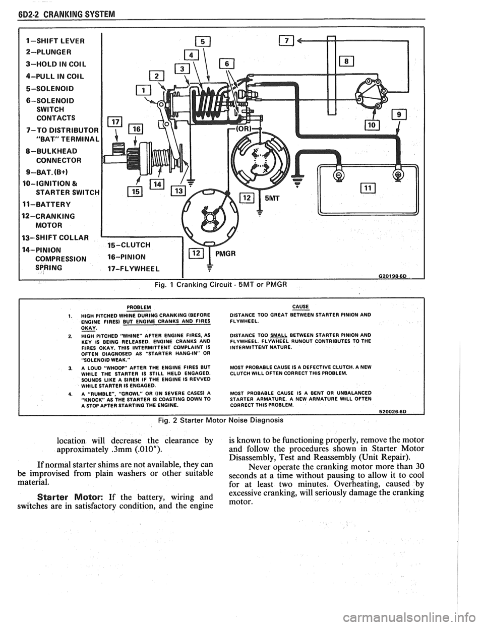
1-SWIFT LEVER m
SPRING 17-FLYWHEEL I
I G20198-6D
Fig. 1 Cranking Circuit - 5MT or PMGR
PROBLEM CAUSE - 1. HIGH PITCHED WHINE DURING CRANKING (BEFORE DISTANCE
TOO GREAT BETWEEN STARTER PINION AND
ENGINE FIRES) BUT ENGINE CRANKS AND FIRES FLYWHEEL.
OKAY - 2. HlGH PITCHED "WHINE"
AFTER ENGINE FIRES, AS
KEY IS BEING RELEASED. ENGINE CRANKS AND
FIRES OKAY. THlS INTERMITTENT COMPLAINT IS
OFTEN DIAGNOSED AS "STARTER HANG-IN"
OR "SOLENOID WEAK."
3. A LOUD "WHOOP" AFTER THE ENGINE FIRES BUT
WHILE THE STARTER IS STILL HELD ENGAGED.
SOUNDS
LIKE A SIREN IF THE ENGINE IS REVVED
WHILE STARTER IS ENGAGED.
4. A "RUMBLE. "GROWL" OR (IN SEVERE CASES) A
"KNOCK" AS THE STARTER IS COASTING DOWN TO
A STOP AFTER STARTING THE ENGINE. DISTANCE
TOO
SMALL BETWEEN STARTER PINION AND
FLYWHEEL. FLYWHEEL RUNOUT CONTRIBUTES TO THE
INTERMITTENT NATURE.
MOST PROBABLE CAUSE IS A DEFECTIVE CLUTCH. A NEW
CLUTCH
WlLL OFTEN CORRECT THlS PROBLEM.
MOST PROBABLE CAUSE IS A BENT OR UNBALANCED
STARTER ARMATURE. A NEW ARMATURE
WlLL OFTEN
CORRECT THlS PROBLEM.
620026.60
Fig. 2 Starter Motor Noise Diagnosis
location will decrease the clearance by is known to be functioning properly, remove the motor
approximately
.3mm (.01OU). and follow the procedures shown in Starter Motor
Disassembly, Test and Reassembly (Unit Repair).
If normal starter shims are not available, they can
Never operate the cranking motor more than 30
be improvised from plain washers or other suitable
seconds at a time without pausing to allow it to cool material.
for at least two minutes. Overheating, caused by
excessive cranking, will seriously
damage the cranking Starter Motor: If the battery, wiring and motor, switches are in satisfactory condition, and the engine
Page 454 of 1825
CRANKING SYSTEM 882-3
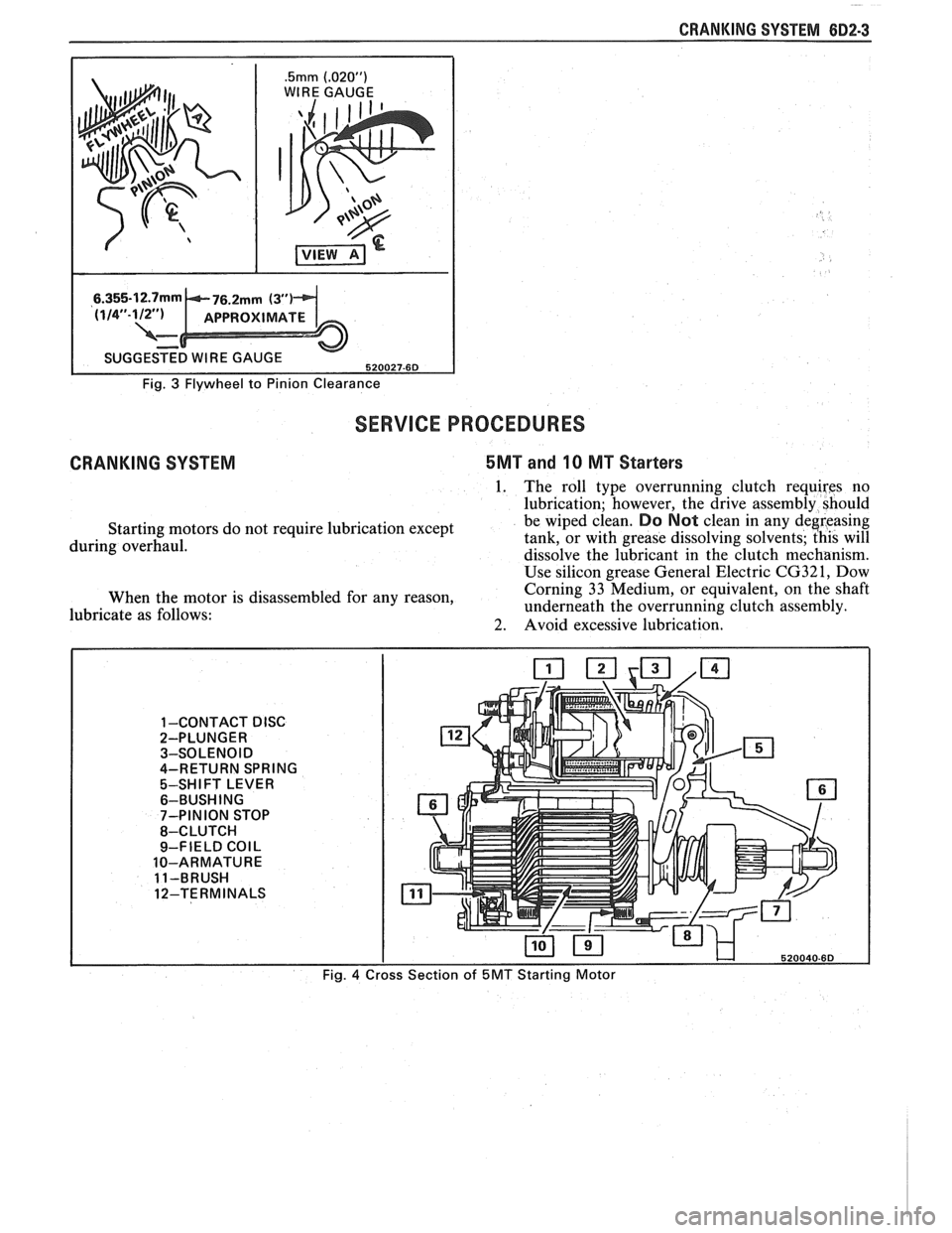
.5mm (.02OU)
WIRE GAUGE
I
Fig. 3 Flywheel to Pinion Clearance
SERVICE PROCEDURES
CRANKING SYSTEM 5MT and 10 MT Starters
1. The roll type overrunning clutch requires no
lubrication; however, the drive assembly should
Starting motors do not require lubrication except be wiped clean.
Do Not clean in
any deereasing
during overhaul. tank, or
with grease dissolving solvents; this will
dissolve the lubricant in the clutch mechanism.
Use silicon grease General Electric
CG321, Dow
When the motor is disassembled for any reason, Corning
33 Medium, or equivalent, on the shaft
lubricate as follows: underneath
the overrunning clutch assembly.
2. Avoid excessive lubrication.
1 -CONTACT DISC 2-PLUNGER
3-SOLENOID
4-RETURN SPRING
5-SHIFT LEVER
6-BUSH ING
7-PINION STOP
8-CLUTCH
9-FIELD
COIL
10-ARMATURE
11-BRUSH
12-TERMINALS
Fig.
4
Page 455 of 1825
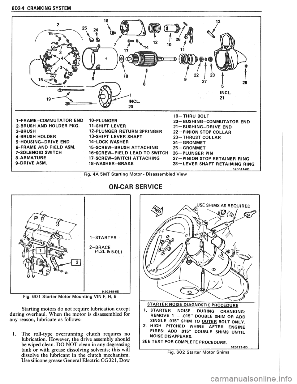
(iD2.4 CRANKING SYSTEM
1-FRAME-COMMUTATOR END
2-BRUSH AND HOLDER PKG.
3-BRUSH
4BRUSH HOLDER
5-HOUSING-DRIVE END
6-FRAME AND FIELD ASM.
7-SOLENOID SWITCH
8-ARMATURE
9-DRIVE ASM. 10-PLUNGER
1 1-SHIFT
LEVER
12-PLUNGER RETURN SPRINGER
13-SHIFT LEVER SHAFT
14-LOCK WASHER
15-SCREW-BRUSH ATTACHING
16-SCREW-FIELD LEAD TO SWITCH
17-SCREW-SWITCH ATTACHING
18-WASHER-BRAKE 19-THRU
BOLT
20- BUSHI NG-COMMUTATOR END
21- BUSHING-DRIVE END
22- PINION STOP COLLAR
23-THRUST COLLAR
24-GROMMET
25-GROMMET
26-PLUNGER PIN
27-PINION STOP RETAINER
RING
28-LEVER SHAFT RETAINING RING
Fig. 4A 5MT Starting Motor - Disassembled View
ON-CAR
H20248-6D
Fig. 601 Starter Motor Mounting VIN F, H, 8
Starting motors do not require lubrication except
during overhaul. When the motor is disassembled for
any reason, lubricate as follows:
1. The roll-type overrunning clutch requires no
lubrication. However, the drive assembly should
be wiped clean. DO NOT clean in any degreasing
tank or with grease dissolving solvents; this will
dissolve the lubricant in the clutch mechanism.
Use silicone grease General Electric
CG32 1, Dow
SERVICE
. - . . . - - . REMOVE 1 - ,015" DOUBLE SHIM OR ADD
SINGLE
.015" SHIM TO OUTER BOLT ONLY.
2. HIGH PITCHED WHINE AFTER ENGINE
FIRES: ADD
.015" DOUBLE SHIMS UNTIL
NOISE DISAPPEARS.
SEE TEXT FOR COMPLETE PROCEDURE.
Fig. 602 Starter Motor Shims
Page 505 of 1825
6E2-A-114 5.OL (VIN E) DRIVEABILITY AND EMISSIONS
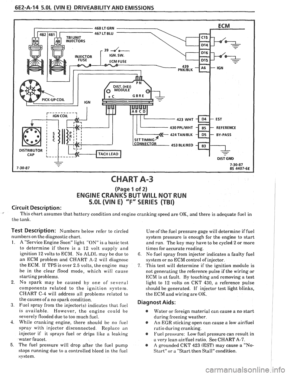
CHART A-3
(Page I of 2)
ENGINE CRANKS BUT WILL NQ"TRUN
5.OL (VIM E) "F"" SERlES (TBI)
Circuit Description:
This chart assumes that battery condition and engine cranking speed are OK, and there is adequate fuel in
the tank.
Test Description: Numbers below refer to circled
numbers on the diagnostic chart.
1. A "Service Engine Soon" light "ON" is a basic test
to determine if there is a 12 volt supply and
ignition 12 volts to ECM. No
ALIII, may be due to
an ECM problem and CHART A-2 will diagnose
the ECM. If TPS is over 2.5 volts, the engine may
be in the clear flood mode, which will cause
starting problems.
2. No spark may be caused by one of several
components related to the ignition system.
CHART
C-4 will address all problems related to
the causes of a no spark condition.
3. Fuel spray from the injector(s) indicates that fuel
is available. However, the engine could be
severely flooded due to too much fuel.
4. While cranking engine, there should be no
f~lel
spray with injector disconnected. Replace an
injector if it sprays fuel or drips like a leaking
water faucet.
5, The fuel pressure will drop after the fuel pump
stops running due to
a controlled bleed in the fuel
system. Use
of the fuel pressure gage will determine
if fuel
system pressure is enough for the engine to start
and run. The key may have to be cycled
2 or more
times for accurate reading.
6. No fuel spray from injector indicates a faulty fuel
system or no ECM control of injector.
7. This test will determine if the ignition module is
not generating the reference pulse if the wiring or
ECM is at fault. By touching and removing
a test
light to 12 volts on CKT 430,
a reference pulse
should be generated. If
injector test light blinks,
the ECM and wiring are
OK.
Diagnost Aids:
@ Water or foreign material can cause a no start
during freezing weather.
@ An EGR sticking open can cause a low airlfuel
ratio during cranking.
@ Fuel pressure: Low fuel pressure can result in
a very lean airlfuel ratio. See CHART A-7.
@ A grounded CKT 423 (EST) may cause a "No-
Start" or a "Start then Stall" condition.
Page 511 of 1825
6EZ-A-20 5.0L (VIN E) DRIVEABILITY AND EMISSIONS
FUEL PRESSURE
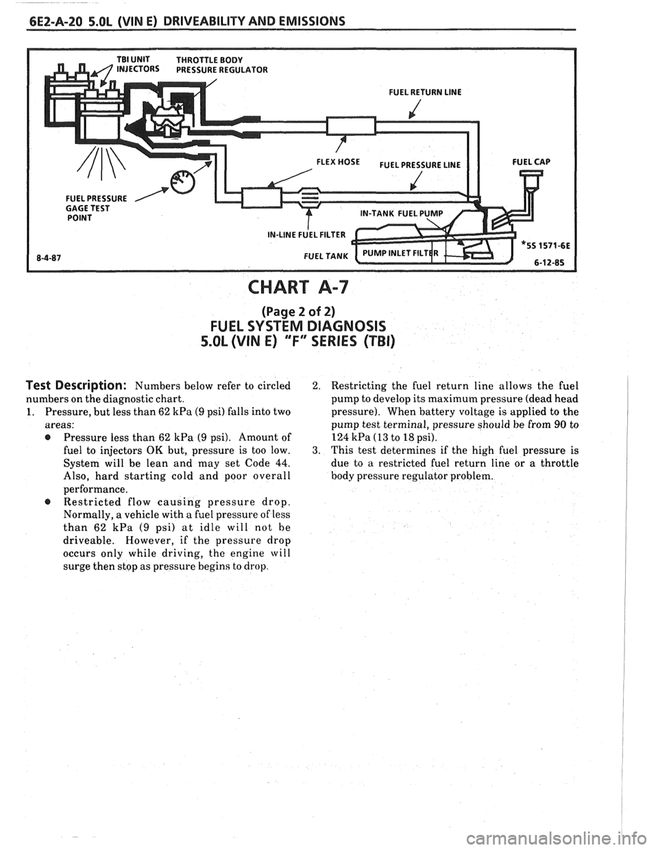
CHART A-7
(Page 2 of 2)
FUEL SYSTEM DIAGNOSIS
5.OL (VIN E) "F" SERIES (TBI)
Test Description: Numbers below refer to circled
numbers on the diagnostic chart.
1. Pressure, but less than 62 kPa (9 psi) falls into two
areas:
@ Pressure less than 62 kPa (9 psi). Amount of
fuel to injectors
OK but, pressure is too low.
System will be lean and may set Code
44.
Also, hard starting cold and poor overall
performance. Restricted flow causing pressure drop.
Normally, a vehicle with a fuel pressure of less
than 62
kPa (9 psi) at idle will not he
driveable. However, if the pressure drop
occurs only while driving,
the engine will
surge then stop as pressure begins to drop.
2. Restricting the fuel return line allows the fuel
pump to develop its maximum pressure (dead head
pressure). When battery voltage is applied to the
pump test terminal, pressure should be from
90 to
124
kPa (13 to 18 psi).
3. This test determines if the high fuel pressure is
due to a restricted fuel return line or a throttle
body pressure regulator problem.
Page 549 of 1825
6EZ-B-2 5.OL (VIN E) DRIVEABILITY AND EMISSIONS
Problem may or may not turn "ON" the "Service Engine Soon" light, or store a code.
DO NOT use the trouble code charts in Section
"A" for intermittent problems. The fault must be
present to locate the problem. If a fault is
intermittent, use of trouble code charts may result
in replacement of good parts.
@ Most intermittent problems are caused by faulty
electrical connections or wiring. Perform
careful check of suspect circuits for:
- Poor mating of the connector halves, or
terminals, not fully seated in the connector
body (backed out).
I - Improperly formed or damaged terminals.
All connector terminals in problem circuit
should be carefully reformed to increase
contact tension.
- Poor terminal to wire connection. This
requires removing the terminal from the
connector body to check as outlined in the
Introduction to Section
"6E".
@ If a visual (physical) check does not find the
cause of the problem, the car can be driven with
a voltmeter connected to a suspected circuit or a
"Scan" tool may be used. An abnormal voltage
reading, when the problem occurs, indicates the
problem may be in that circuit. If the wiring
and connectors check OK, and a trouble code was
stored for a circuit having a sensor, except
for Codes 44 and 45, substitute a known good
sensor and recheck.
@ Loss of trouble code memory. To check,
disconnect TPS and idle engine until "Service
Engine Soon" light comes
"ON". Code 22 should
be stored, and kept in memory, when ignition is
turned "OFF" for at least 10 seconds. If not, the
ECM
is faulty.
@ An intermittent "SES" light, and no trouble
codes, may be caused by:
- Electrical system interference caused by a
defective relay, ECM driven solenoid, or switch.
They can cause a sharp electrical surge.
Normally, the problem will occur when the
faulty component is operated.
- Improper installation of electrical options, such
as lights, 2-way radios, etc.
- EST wires should be routed away from spark
plug wires, ignition system components, and
generator. Wire for CKT 453 from ECM to
ignition system should be a good ground.
- Ignition secondary shorted to ground.
- CKTs 419 ("SES" light) or 451 (Diagnostic Test)
intermittently shorted to ground.
- ECM power grounds.
HARD START
Definition: Engine cranks OK, but does not start for a long
time. Does eventually run, or may start but immediately dies.
, <
@ CHECK: 4. Connect a radiator test pump to the line and
- For water contaminated fuel. apply 103 kPa (15 psi) pressure. If the
- Fuel system pressure CHART A-7. pressure will hold for 60 seconds, the check
- TPS for sticking or binding should read less than
valve is OK.
1.25 volts on a "Scan" tool. @ Check ignition system for:
- No crank signal; see CHART C-1B. - Proper output with ST-125.
- EGR operation; CHART C-7. - Worn shaft.
- Fuel System - CHART A-7. - Rare and shorted wires.
- For a faulty in-tank fuel pump check valve, - Pickup coil resistance and connections.
which would allow the fuel in the lines to drain
- Loose ignition coil connections.
back to the tank after the engine is stopped. To
- Moisture in distributor cap.
check for this condition:
- Spark plugs, wet plugs, cracks, wear,
1. Ignition "OFF".
improper gap, burned electrodes, or heavy
2. Disconnect fuel line at the filter
deposits.
3. Remove the tank filler cap. @ If engine starts but then, immediately stalls,
open distributor bypass line. If engine then
starts, and runs OK, replace distributor pickup
coil.
@ Check CKT 423 (EST) for short to ground.