1988 PONTIAC FIERO stop start
[x] Cancel search: stop startPage 821 of 1825
6E3-A-18 5.OL (WIN F) & 5.7L(VIN 8) DRIVEABILITY AND EMISSIONS
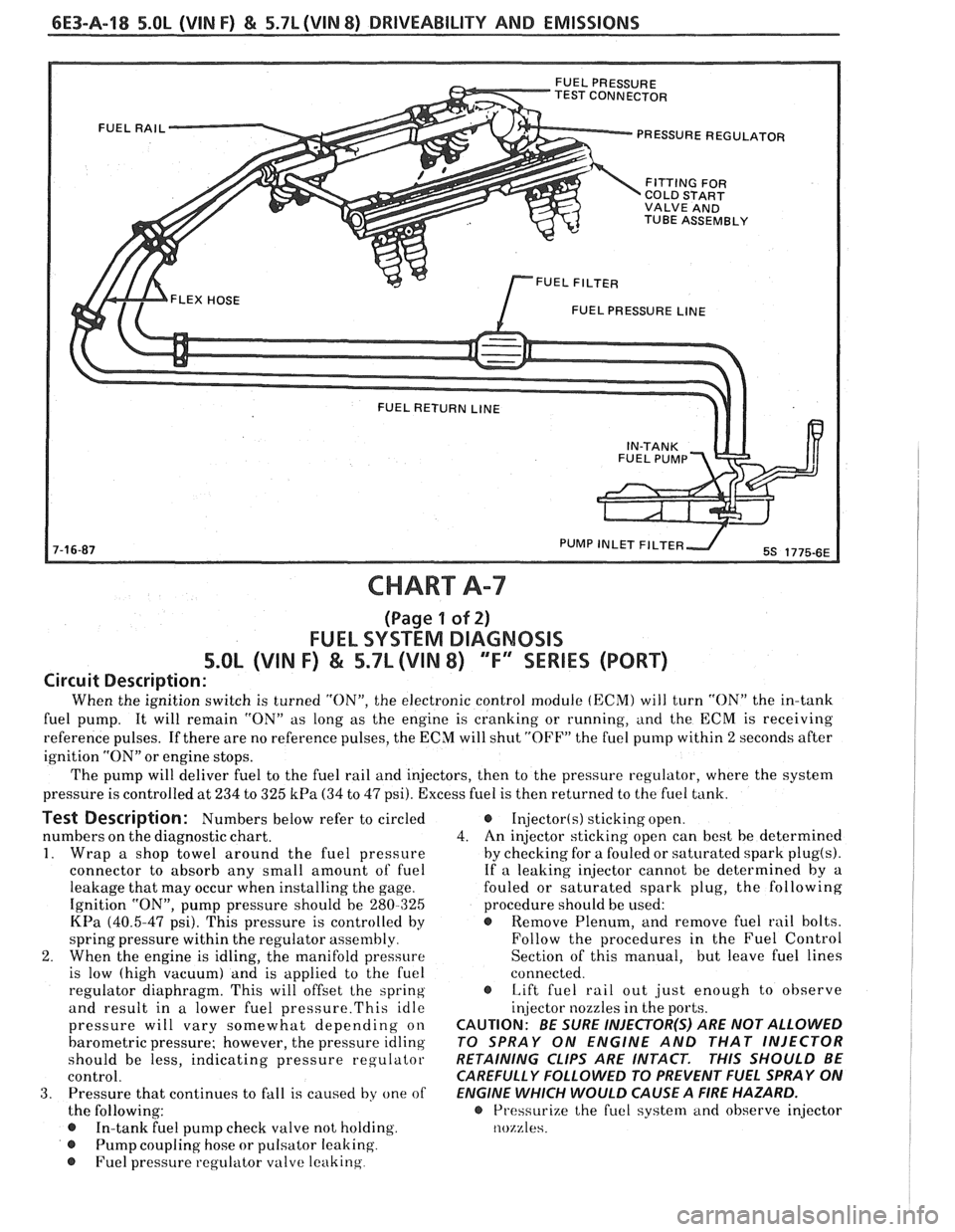
PRESSURE REGULATOR
COLD START
TUBE ASSEMBLY
FUEL PRESSURE
LINE
CHART A-7
(Page 1 of 2)
FUEL SYSTEM DIAGNOSIS
5.OL (VIN F) & 5.7L (VIN 8) 'TF'3SERlES (PORT)
Circuit Description:
When the ignition switch is turned "ON", the electronic control module (ECM) will turn "ON" the in-tank
fuel pump. It will remain "ON" as long as the engine is cranking or running, and the
ECM is receiving
reference pulses. If there are no reference pulses, the ECM will shut "OFF" the fuel pump within 2 seconds after
ignition "ON" or engine stops.
The pump will deliver fuel to the fuel rail and injectors, then to the pressure regulator, where the system
pressure is controlled at 234 to 325
kPa (34 to 47 psi). Excess fuel is then returned to the fuel tank.
Test Description: Numbers below refer to circled
numbers on the diagnostic chart.
1. Wrap a shop towel around the fuel pressure
connector to absorb any small amount of fuel
leakage that may occur when installing the gage.
Ignition "ON", pump pressure should be 280-325
KPa (40.5-47 psi). This pressure is controlled by
spring pressure within the regulator
assenlbly
2. When the engine is idling, the manifold pressure
is low (high vacuum) and is applied to the fuel
regulator diaphragm. This will offset
the spring
and result in a lower fuel
pressure.This idle
pressure will vary somewhat depending on
barometric pressure; however, the pressure idling
should be less, indicating pressure regulator
control.
3. Pressure that continues to fall is caused by one of
the following:
In-tank fuel pump check valve not holding.
@ Pump coupling hose or pulsator leaking
@ Fuel pressure regulator valve leaking
Injector(s) sticking open.
4. An
injector sticking open can best be determined
by checking for a fouled or saturated spark
plug(s).
If a leaking injector cannot be determined by a
fouled or saturated spark plug, the following
procedure should be used:
@ Remove Plenum, and remove fuel rail bolts.
Follow the procedures in the Fuel Control
Section of this manual, but leave fuel lines
connected.
s Lift fuel rail out just enough to observe
injector nozzles in the ports.
CAUTION: BE SURE INJECTOR(S) ARE NOT ALLOWED
TO SPRAY ON ENGINE AND THAT INJECTOR
RETAINING CLIPS ARE INTACT.
THIS SHOULD BE
CAREFULLY FOLLOWED TO PREVENT FUEL SPRAY ON
ENGINE WHICH WOULD CAUSE A
FIRE HAZARD.
@ Pressurize the fuel syste~rl and observe injector
nozzles.
Page 823 of 1825
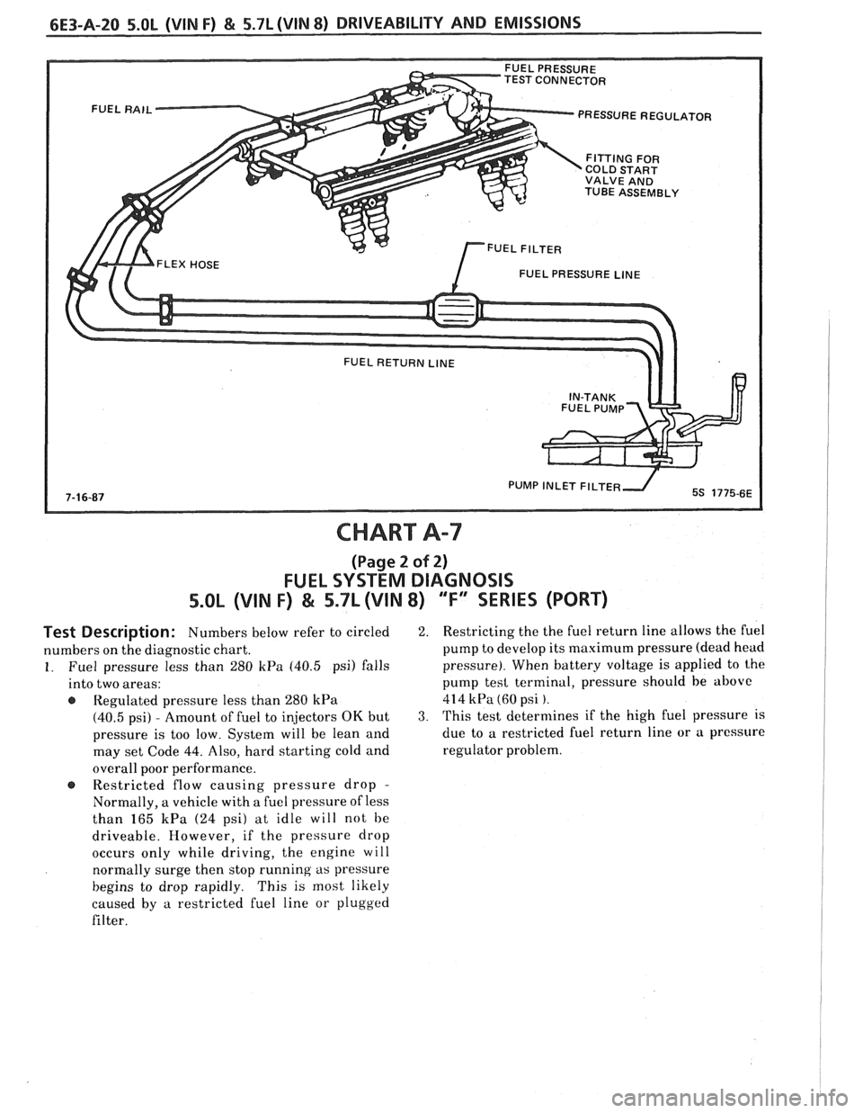
TEST CONNECTOR PRESSURE REGULATOR
COLD START
VALVE AND
TUBE ASSEMBLY
FUEL PRESSURE
LINE
PUMP INLET FlLTE
CHART A-7
(Page 2 of 2)
FUEL SYSTEM DIAGNOSIS
5.OL (VIN F) & 5.7L (VIN 8) "F" SERIES (PORT)
Test Description: Numbers below refer to circled
numbers on the diagnostic chart.
1. Fuel pressure less than 280 kPa (40.5 psi) falls
into two areas:
Regulated pressure less than
280 kPa
(40.5 psi) - Amount of fuel to injectors OK but
pressure is too low. System will be lean and
may set Code
44. Also, hard starting cold and
overall poor performance.
@ Restricted flow causing pressure drop -
Normally, a vehicle with a fuel pressure of less
than
165 kPa (24 psi) at idle will not be
driveable. However, if the pressure drop
occurs only while driving, the engine will
normally surge then stop running
as pressure
begins to drop rapidly. This is most likely
caused by
a restricted fuel line or plugged
filter.
2. Restricting the the fuel return line allows the fuel
pump to develop its maximum pressure (dead head
pressure). When battery voltage is applied to the
pump
tesl terminal, pressure should be above
414 kPa (60 psi ).
3. This test determines if the high fuel pressure is
due to
a restricted fuel return line or a pressure
regulator problem.
Page 843 of 1825
CODE 32
EXHAUST GAS RECBRCULATION (EGR) CIRCUIT
%.OL (VIN F) & 5.7L (VIN 8) "F" SERIES (PORT)
Circuit Description:
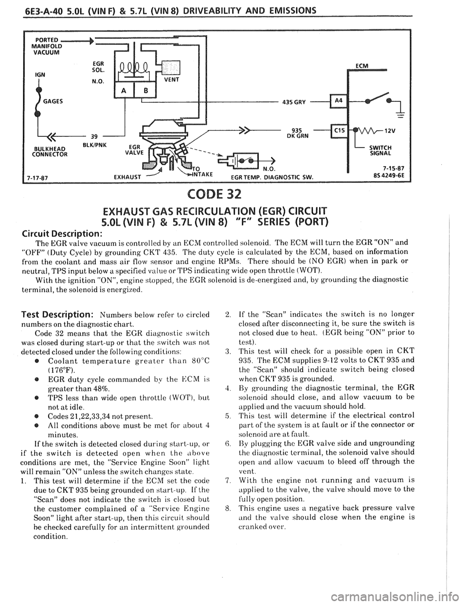
The EGR valve vacuum is controlled by an ECM controlled solenoid. 'I'he ECM will turn the EGR "ON" and
"OFF" (Duty Cycle) by grounding CKT 435. 'I'he duty cycle is calculated by the ECM, based on information
from the coolant and mass air flow sensor and engine
RPMs. 'I'here should be (NO EGR) when in park or
neutral,
TPS input below a specified value or TPS indicating wide open throttle (WOT).
With the ignition "ON", engine stopped, the EGR solenoid is de-energized and, by grounding the diagnostic
terminal, the solenoid is energized.
Test Description: Numbers below refer to circled
numbers on the diagnostic chart.
Code 32 means that the
EGR diagnostic switch
was closed during start-up or that the switch was not
detected closed under the following conclilions:
@ Coolant temperature greater than 80°C
( 176°F).
@ EGR duty cycle commanded by the ISCM is
greater than
48%.
@ TPS less than wide open throttle (WO'I'), but
not at idle.
@ Codes 21,22,33,34 not present.
@ All conditions above must be met for about 4
minutes.
If the switch is detected closed during start-up, or
if the switch is detected open when the
,lbove
conditions are met, the "Service Engine Soon" light
will remain
"ON" unless the switch changes state.
1. This test will determine if the ECM set the code
due to CKT 935 being grounded on start-up.
If the
"Scan" does not indicate the switch is closed but
the customer complained of a "Service Engine
Soon" light after start-up, then this circuit should
be checked carefully for an intermittent grounded
condition.
2. If the "Scan" indicates the switch is no longer
closed after disconnecting it, be sure the switch is
not closed due to heat.
(EGR being "ON" prior to
test).
3. 'I'his test will check for
u possible open in CKT
935. 'I'he EXM supplies 9-12 volts to CKrl' 935 and
the "Scan" should indicate switch being closed
when CK'P 935 is grounded.
4. By grounding the diagnostic terminal, the EGR
solenoid should close, and allow vacuum to be
applied and the vacuum should hold.
5. This test will determine if the electrical control
part of the system is at fault or if the connector or
solenoid are at fault.
6. I3y plugging the EGR valve side and ungrounding
the diagnostic terminal, the solenoid valve should
open and allow vacuum to bleed off through the
vent.
7. With the engine not running and vacuum is
applied to the valve, the valve should
move to the
fully open position.
8. 'I'his engine uses a negative back pressure valve
and the valve should close when the engine is
cranked over.
Page 868 of 1825
DRIVEABILITY AND EMISSIONS 5.OL (VIN F) & 5.7L (VIN 8) 6E3-8-3
@ A faulty in-tank fuel pump check valve will @
allow the fuel in the lines to drain back to the
tank after the engine is stopped. To check for
this condition:
e
Perform Fuel System Diagnosis, CHART A-7.
@ Remove spark plugs. Check for wet plugs,
cracks, wear, improper gap, burned electrodes,
@
or heavy deposits. Repair or replace as
necessary. If
engine starts but then immediately stalls
open distributor by-pass line. If engine then
starts and runs OK, replace pickup coil.
If engine starts and stalls disconnect MAF
sensor. If engine then
r~lns and sensor
connections are OK, replace
thr. )t.ft+rl'.
Basic engine problem.
HESITATION, SAG, STUMBLE
Definition: Momentary lack of response as the accelerator i., pl,ihcc! dowt-
Can occur at all car speeds. Usually most severe when first tryine, lo m,tlir. LII~.
car move, as from a stop sign. May cause the engine to sta!! 1, e er., riu~~~!~
s Perform careful visual check as described at
start of Section
"B".
@ CHECK:
- Fuel pressure. See CHART A-7. Also, check
for water contaminated fuel.
- Air leaks at air duct between MAF sensor and
throttle body.
- Spark plugs for being fouled or faulty wiring.
- Mem-Cal number. Also check service bulletins
for latest Mem-Cal.
- TPS for binding or sticking. Voltage should
increase at
a steady rate as throttle is moved
toward WOT.
- Ignition timing. See emission control
information label.
- Generator output voltage. Repair if less than 9
or more than 16 volts.
- HE1 ground, CKT 453.
- Canister purge system for proper operation.
See CHART C-3.
- EGR - See CHART C-7.
e Perform injector balance test CHART C-2A.
SURGES AND/OR CHUGGLE
Definition: Engine power variation under steady
throttle or cruise. Feels like the car speeds up and
slows down with no change in the accelerator pedal.
@ Be sure driver understands transmission
converter clutch and
AJC compressor operation
in owner's manual.
Perform careful visual inspection as described
at start of Section
"B".
e CHECK:
- Loose or leaking air duct between MAF sensor
and throttle body.
- Generator output voltage. Repair if less than 9
or more than 16 volts.
- EGR - There should be no EGR at idle. See
CHART C-7.
- Vacuum lines for kinks or leaks.
- Ignition timing. See emission control
information label.
- In-line fuel filter. Replace if dirty or plugged.
- Fuel pressure while condition exists. See
CHART A-7.
@ Inspect oxygen sensor for silicon contamination
from fuel, or use of improper RTV sealant. The
sensor may have a white, powdery coating and
result in a high but false signal voltage (rich
exhaust indication). The ECM will then reduce
the amount of fuel delivered to the engine,
causing a severe driveability problem.
@ Remove spark plugs. Check for cracks, wear,
improper gap, burned electrodes, or heavy
deposits. Also check condition of distributor
cap, rotor, and spark plug wires.
@ To help determine if the condition is caused by a
rich or lean system, the car should be driven at
the speed of the complaint. Monitoring block
learn at the complaint speed will help identify
the cause of the problem.
If the system is lean
(block learn greater than
1381, refer to
"Diagnostic Aids"
on facing page of Code 44. If
the system is running rich (block learn less than
1181, refer to "Diagnostic Aids" on facing page
of Code
45.
Page 900 of 1825
DRIVEABILITY AND EMISSIONS 5.OL (VIN F) & 5.7b (VIN 8) 6E3-CZ-13
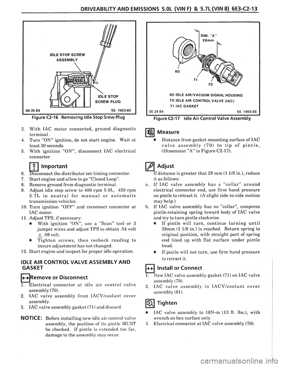
IDLE STOP SCREW
ASSEMBLY
IDLE STOP
SCREW PLUG
Figure C2-16 Removing Idle Stop Srew Plug
60 IDLE AIR/VACUUM SIGNAL HOUSING
70 IDLE AIR CONTROL VALVE (IAC)
71 IAC GASKET
Figure C2-17 Idle Air Control Valve Assembly
3. With IAC motor connected, ground diagnostic
terminal. Measure
4. Turn "ON" ignition, do not start engine. Wait at @ Distance from gasket mounting surface of IAC
least 30 seconds. valve assembly
(70) to tip of pintle,
5. With ignition
"ON", disconnect IAC electrical (Dimension
"A" in Figure C2-17).
connector.
Important
6. Disconnect
the distributor set-timing connector.
7. Start
engine and allow to go "Closed Loop".
8. Remove
ground from diagnostic terminal.
9. Adjust idle stop screw to 400 rpm 5.01,, 450 rpm
5.7L in neutral for manual or automatic
transmission vehicles.
10. Turn ignition "OFF" and reconnect connector at
IAC motor.
11. Adjust TPS, if necessary:
@ With ignition "ON", use a "Scan" tool or 3
jumper wires and adjust TPS to obtain .54 volt
+ .08 volt. - @ Tighten screws, then recheck reading to
insure adjustment has not changed.
12. Start engine and inspect for proper idle operation.
IDLE AIR CONTROL VALVE ASSEMBLY AND
CASKET
ORemove or Disconnect
1. Electrical connector at idle air control valve
assembly (70).
2. IAC valve assembly from IACVIcoolant cover
assembly.
3. IAC valve assembly gasket (71) and discard.
NOTICE: Before installing new idle air control valve
assembly, the position of its
pinlle MUST
be checked. If pintle is extended too far,
damage to the assembly
may occur
Adjust
If distance is greater that 28 mm (1 118 in.), reduce
it as follows:
a. If IAC valve assembly has a "collar" around
electrical connector end, use firm hand pressure
on pintle to retract it. (A slight side-to-side motion
may help.)
b. If
IAC valve assembly has no "collar", compress
pintle-retaining spring toward body of IAC valve
and try to turn pintle clockwise.
@ If pintle will turn, continue turning until
28mm
(1 118 in.) is reached. Return spring to
original position, with straight part of spring
end lined up with flat surface under pintle
head.
@ If pintle will not turn, use firm hand pressure
to retract it.
Install or Connect
1. New IAC valve assembly gasket (71) on IAC valve
assembly
(70).
2. IAC valve assembly in IACVIcoolant cover
assembly (61).
Tighten
IAC valve assembly to 18N.m (13 ft. Ibs.), with
wrench on hex surface only.
3. Electrical connector at IAC valve assembly (70).
Page 902 of 1825
DRIVEABILITY AND EMISSIONS 5.OL (WIN F) & 5.7L (WIN 8) 6E3-C2-15
Important
No physical adjustment is made to the IAC
assembly after installation. IAC
valve resetting
occurs after reinstallation on the vehicle, and is
reset after the engine is started and then the
ignition turned "OFF".
THROTTLE BODY
PARTS INFORMATION
FIGURE CZ-18
PART NAME PART #
. Gasket Flange ......................... 1
Throttle Body Assembly .................. 10
Plug . Idle Stop Screw .................... 15
Screw Assembly - Idle Stop. ................ 16
Spring
- Idle Stop Screw ................... 17
Sensor - Throttle Position (TPS) ............. 20
Screw Assembly
- TPS Attaching ............ 21
Retainer
- TPS Attaching Screw ............. 22
Cover-CleanAir........................ 41
Screw Assembly
- Clean Air Cover
Attaching...
.......................... 42
Gasket
- Clean Air Cover .................. 43
IACVICoolant Cover Assembly ............. 61
Screw Assembly
- IACV Cover
Assembly to Throttle Body
................ 62
Gasket
- IACVICoolant Cover to
Throttle Body..
........................ 63
Valve Assembly
- ldle Air Control
(IAC) ................................ 70
Gasket
- IAC Valve Assembly .............. 71
CLEAN AIR COVER AND GASKET
ORemove or Disconnect
1. Clean
air cover attaching screw assemblies (42)
2. Clean air cover (41).
3. Clean air cover gasket (43).
@ Cover mounting surface to ensure a good seal.
Install and Connect
1. New clean air cover gasket (43) on throttle body
assembly
(10).
2. Clean air cover (41).
3. Clean air cover attaching screw assemblies (42).
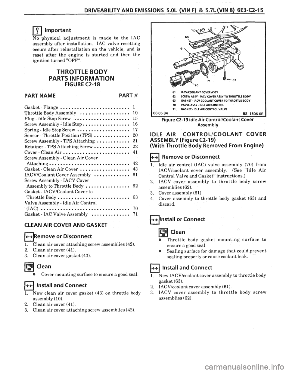
61 IACVICOOLANT COVER ASSV 62 SCREW ASSY . IACV COVER ASSY TO THROrRE BODV 63 GASKET. IACV COOLANT COVER TO THROTTLE BODY 70 VALVE ASSV -IDLE AIR CONTROL 71 GASKET - IDLE AIR COHTROLVALVE
Figure C2-19 ldle Air Control/Coolant Cover
Assembly
IDLE AIR CONTRBLICOOLANT COVER
ASSEMBLY (Figure
CZ-19)
(With Throttle Body Removed From Engine)
a Remove or Disconnect
1. Idle
air control (IAC) valve assembly (70) from
IACVIcoolant cover assembly. (See "Idle Air
Control Valve and Gasket" instructions.)
2. IACV
cover assembly to throttle body screw
assemblies
(62).
3. Cover assembly (61).
4. Cover
assembly to throttle body gasket (63) and
discard.
alnstall or Connect
Clean
e Throttle body gasket mounting surface to
ensure a good seal.
e Sealing surface for damage that could prevent
sealing properly or
cause coolant leak.
a Install and Connect
1. New IACVIcoolant cover
assembly to throttle body
gasket
(63).
2. IACV/coolant cover assembly (61).
3. IACV
cover assembly to throttle body screw
assemblies
(62).
Page 907 of 1825
6E3-C2-20 5.0L (VIN F) & 5.7L (WIN 8) DRIVEABILITY AND EMISSIONS
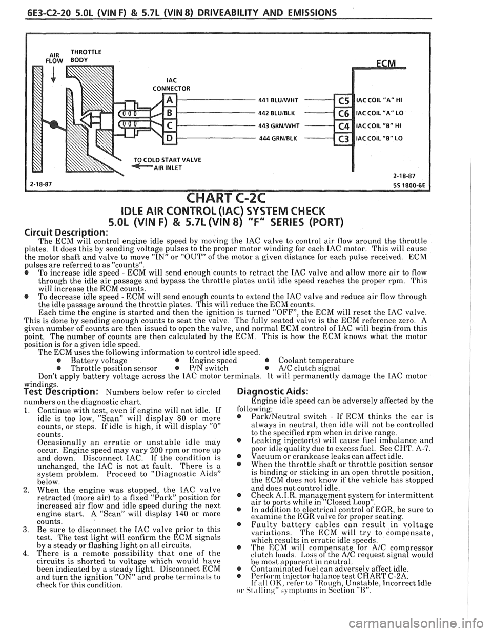
CONNECTOR - 441 BLUMlHT C5 IAC C0lL1'A" HI - 442 BLUIBLK C6 IAC COIL "A" LO - 443 GRNMlHT C4 IAC COIL "B" HI - 444 GRNIBLK C3 lAC COIL "B" LO v
START VALVE
CHART C-2C
IDLE AIR CONTROL (IAC) SYSTEM CHECK
S.OL (VIN F) & 5.7L (VIN 8) "F'" SERIES (PORT)
Circuit Description:
The ECM will control engine idle speed by moving the IAC valve to control air flow around the throttle
plates. It does this by sending voltage pulses to the proper motor winding for each IAC motor. This will cause
the motor shaft and valve to move
"IN" or "OUT" of the motor a given distance for each pulse received. ECM
pulses are referred to as "counts".
@ To increase idle speed - ECM will send enough counts to retract the IAC valve and allow more air to flow
through the idle air passage and bypass the throttle plates until idle speed reaches the proper rpm. This
will increase the ECM counts.
e To decrease idle speed - ECM will send enough counts to extend the IAC valve and reduce air flow through
the idle passage around the throttle plates. This will reduce the ECM counts.
Each time the engine is started and then the ignition is turned "OFF", the ECM will reset the IAC valve.
This is done by sending enough counts to seat the valve.
The fully seated valve is the ECM reference zero. A
given number of counts are then issued to open the valve, and normal ECM control of IAC will begin from this
point. The
number of counts are then calculated by the ECM. This is how the ECM knows what the motor
position is for a given idle speed.
The ECM uses the following information to control idle speed.
@ Battery voltage @ Engine speed @ Coolant temperature @ Throttle position sensor @ PIN switch e A/C clutch signal
Don't apply battery voltage across the IAC motor terminals. It will permanently damage the IAC motor
windin s. Test 6escription: Numbers below refer to circled
numbers on the diagnostic chart.
1. Continue with test, even if engine will not idle. If
idle is too low, "Scan" will display 80 or more
counts, or steps. If idle is high, it will display
"0"
counts.
Occasionally an erratic or unstable idle
[nay occur. Engine speed may vary 200 rpm or more up
and down. Disconnect IAC. If the condition is
unchanged, the IAC is not at fault.
There is a
system problem. Proceed to "Diagnostic Aids"
below.
2. When the engine was stopped, the IAC valve
retracted (more air) to
a fixed "Park" position for
increased air flow and idle speed during the next
engine start. A "Scan" will display 140 or more
coiints. 3. Be sure to disconnect the IAC valve prior to this
test.
The test light will confirm the ECM signals
by a steady or flashing light on all circuits.
4. There is a remote possibility that one of the
circuits is shorted to voltage which would have
been indicated by a steady light. Disconnect ECM
and turn the ignition "ON" and probe terminals to
check for this condition.
Diagnostic Aids:
Engine idle speed can be adversely affected by the
following:
@ ParMNeutral switch - If ECM thinks the car is
always in neutral, then idle will not be controlled
to the specified rpm when in drive range.
@ Leaking injector(s) will cause fuel imbalance and
poor idle quality due to excess fuel. See CHT.
A-7. @ Vacuum or crankcase leaks can affect idle. @ Whenthethrottleshaftorthrottlepositionsensor
is binding or sticking in an open throttle position,
the ECM does not know if the vehicle has stopped
and does not control idle.
@ Check A.I.R. management s stem for intermittent
air to orts while in "~losed~oo~". @ In ad&tion to electrical control of EGR, be sure to
examine the EGR valve for proper seating.
@ Faulty battery cables can result in voltage
variations. The ECM will try to compensate,
which results in erratic idle speeds.
@ 'I'he ECM will com ensate for A/C com ressor
clutch loacls. [.ass ofthe NC request sign8 would
he 11lost apparent, in neutral. @ Contalninatecl fuel can adverse1 affect idle. @ Perform i~!jector balance test C~ART C-2A. If ,111 OK, refer to "Rough, Unstable, Incorrect Idle or St ,tllinqW SJ tnptcfinsiin S~'ction "11''.
Page 913 of 1825
6E3-C3-4 5.OL (VIN F) & 5.7L (VIN 8) DRIVEABILITY AND EMISSIONS
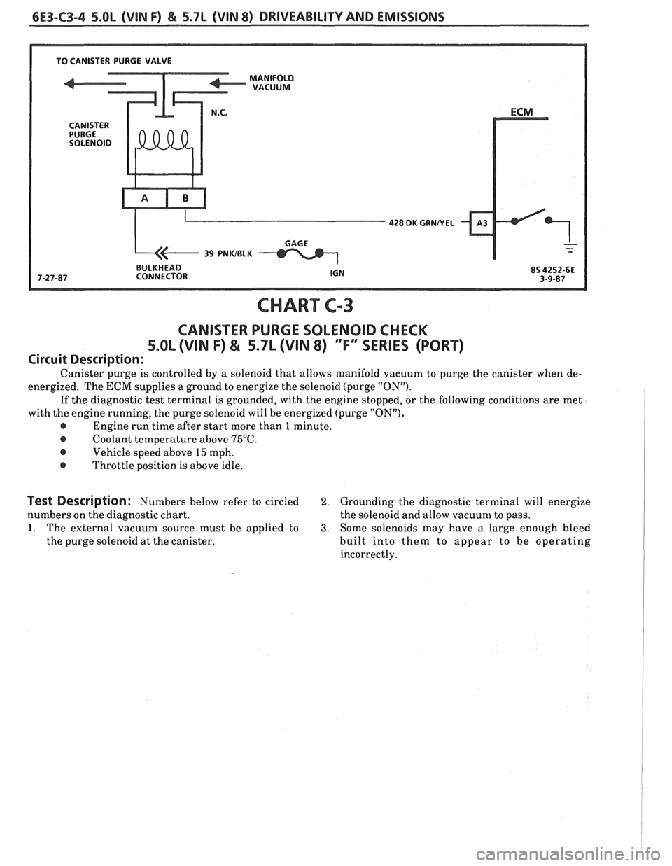
428 DK GUNNEL
BULKHEAD
CHART
CANISTER PURGE SOLENOID CHECK
5.OL (VIN F) & 5.7L (VIN 8) ""FYSERIES (PORT)
Circuit Description:
Canister purge is controlled by a solenoid that allows manifold vacuum to purge the canister when de-
energized. The
ECM supplies a ground to energize the solenoid (purge "ON").
If the diagnostic test terminal is grounded, with the engine stopped, or the following conditions are met
with the engine running, the purge solenoid will be energized (purge "ON").
@ Engine run time after start more than 1 minute.
@ Coolant temperature above 75°C.
@ Vehicle speed above 15 mph.
@ Throttle position is above idle.
Test Description: Numbers below refer to circled 2. Grounding the diagnostic terminal will energize
numbers on the diagnostic chart. the solenoid and allow vacuum to pass.
1. The external vacuum source must be applied to 3. Some solenoids may have a large enough bleed
the purge solenoid at the canister. built into them to appear to be operating
incorrectly.