1988 PONTIAC FIERO stop start
[x] Cancel search: stop startPage 673 of 1825
6E3-A-28 2.8b (VIN 9) DRIVEABILITY AND EMISSIONS
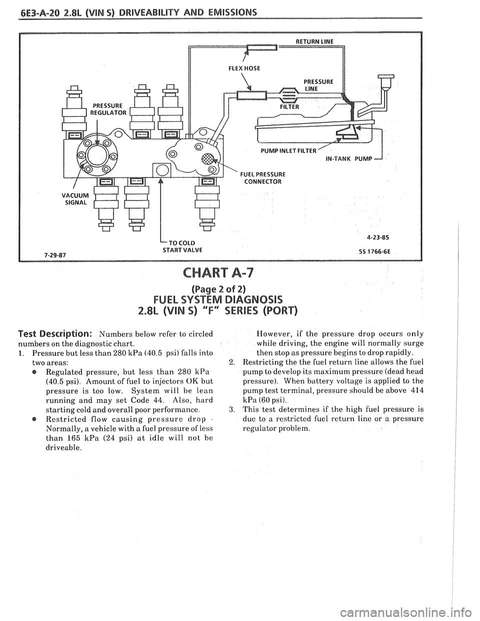
PUMP INLET FILTER
IN-TANK PUMP
FUEL PRESSURE CONNECTOR
CHART A-7
(Page 2 sf 2)
FUEL SYSTEM DIAGNOSIS
2.8L (VIN S) ""FYSEWlES (PORT)
Pest Description: Numbers below refer to circled
numbers on the diagnostic chart.
1. Pressure but less than 280
kPa (40.5 psi) falls into
two areas:
@ Regulated pressure, but less than 280 kPa
(40.5 psi). Amount of fuel to injectors OK but
pressure is too low. System will be lean
running and may set Code 44. Also, hard
starting cold and overall poor performance.
Restricted flow causing pressure drop
-
Normally, a vehicle with a fuel pressure of less
than 165
kPa (24 psi) at idle will not he
driveable. However,
if the pressure drop occurs only
while driving, the engine will normally surge
then stop as pressure begins to drop rapidly.
2. Restricting the the fuel return line allows the fuel
pump to develop its
maximum pressure (dead head
pressure). When battery voltage
is applied to the
pump test terminal, pressure should be above 414
kPa (60 psi).
3. This test determines if the high fuel pressure is
due to a restricted fuel return line or a pressure
regulator problem.
Page 693 of 1825
6E3-A-40 2.8L (VIN 5) DRIVEABILITY AND EMISSIONS
VENT FILTER
450 BLWHT ITCH SIGNAL -
CODE 32
EGR SYSTEM FAILURE
2.8L (VIN S) "F" "SERIES (PORT)
Circuit Description:
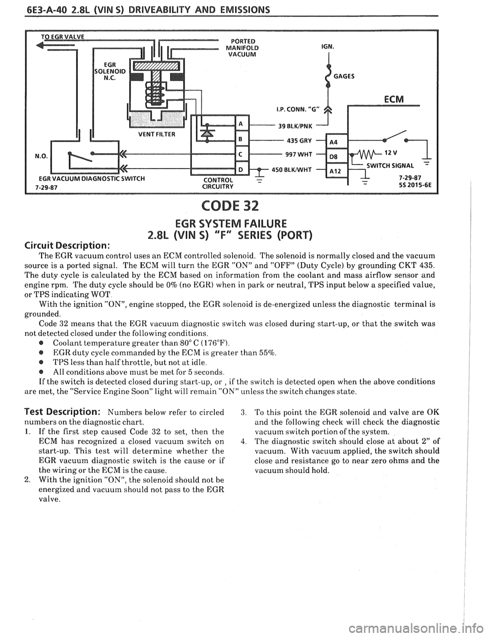
The EGR vacuum control uses an ECM controlled solenoid. The solenoid is normally closed and the vacuum
source is a ported signal. The ECM will turn the EGR "ON" and "OFF" (Duty Cycle) by grounding CKT
435.
The duty cycle is calculated by the ECM based on information from the coolant and mass airflow sensor and
engine rpm. The duty cycle should be
0% (no EGR) when in park or neutral, TPS input below a specified value,
or TPS indicating WOT
With the ignition
"ON", engine stopped, the EGR solenoid is de-energized unless the diagnostic terminal is
grounded. Code 32 means that the EGR vacuum diagnostic switch was closed during start-up, or that the switch was
not detected closed under the following conditions.
@ Coolant temperature greater than 80" C (176°F).
@ EGR duty cycle commanded by the ECM is greater than 55%.
@ TPS less than half throttle, but not at idle.
@ All conditions above must be met for 5 seconds.
If the switch is detected closed during start-up, or
, if the switch is detected open when the above conditions
are met, the "Service Engine Soon" light will remain "ON" unless the switch changes state.
Test Description: Numbers below refer to circled 3. 'Po this point the EGR solenoid and valve are OK
numbers on the diagnostic chart. and the following check will check the diagnostic
1. If the first step caused Code 32 to set, then the vacuutn switch portion of the system.
ECM has recognized a closed vacuum switch on
4. The diagnostic switch should close at about 2" of
start-up. This test will determine whether the
vacuum. With vacuum applied, the switch should
EGR vacuum diagnostic switch is the cause or if close and resistance go to near zero ohms and the
the wiring or the ECM is the cause. vacuum should hold.
2. With the ignition "ON", the solenoid should not be
energized and vacuum should not pass to the EGR
valve.
Page 698 of 1825
DRIVEABILITY AND EMISSIONS 2.8L (VIN S) 6E3-A-45
START AND IDLE ENGINE FOR 1 MINUTE OR
DISCONNECT MAF SENSOR ELECTRICAL CONNECTOR.
IGNITION "ON", ENGINE STOPPED.
CONNECT VOLTMETER BETWEEN HARNESS
CLEAR CODES AND CONFIRM "CLOSED LOOP" OPERATION AND NO "SERVICE ENGINE SOON" LIGHT.
Page 712 of 1825
DRIVEABILITY AND EMISSIONS 2.8L (VIN S) 6E3-B-3
e A faulty in-tank fuel pump check valve will @ If engine starts but then immediately stalls,
allow the fuel in the lines to drain back to the open
distributor by-pass line. If engine then
tank after the engine is stopped. To check for starts
and runs OK, replace pickup coil.
this condition:
@ If engine starts and stalls, disconnect MAF
Perform Fuel System Diagnosis, CHART A-7. sensor. If engine then runs and sensor
@ Remove spark plugs. Check for wet plugs, connections are OK, replace the sensor.
cracks, wear, improper gap, burned
f lectrodes,
or heavy deposits. Repair or replace as
necessary.
HESITATION, SAG, STUMBLE
Definition: Momentary lack of response as the accelerator is pushed down. Can
occur at all car speeds.
Usually most severe when first trying to make the car move, as
from a stop sign. May cause the engine to stall if severe enough.
Perform careful visual check as described at
start of Section
"B".
a CHECK:
- Fuel pressure. See CHART A-7. Also check for
water contaminated fuel.
- Air leaks at air duct between MAF sensor and
throttle body.
- Spark plugs for being fouled or faulty wiring.
- PROM (2.8L) or MEM-CAL (5.OL & 5.7L)
number. Also check service bulletins for latest
MEM-CAL or PROM.
- TPS for binding or sticking. Voltage should
increase at a steady rate as throttle is moved
toward WOT.
- Ignition timing. See Emission Control
Information label.
- Generator output voltage. Repair if less than 9
or more than 16 volts.
- HE1 ground, CKT 453.
- Canister purge system for proper operation.
See CHART C-3.
- EGR - See CHART C-7.
@ Perform injector balance test CHART C-2A.
SURGES AND/OR CHUGGLE
Definition: Engine power variation under steady
throttle or cruise. Feels like the car speeds up and
slows down with no change in the accelerator pedal.
Be sure driver understands transmission
converter clutch and
A/C compressor operation
in Owner's Manual.
e Perform careful visual inspection as described
at start of Section
"B".
CHECK:
- TCC and 4th gear switch operation - See
CHART C-8A.
- Loose or leaking air duct between MAF sensor
and throttle body.
- Generator output voltage. Repair if less than 9
or more than 16 volts.
- EGR - There should be no EGR at idle. See
CHART C-7. Also check for plugged EGR
solenoid filter.
- Vacuum lines for kinks or leaks.
- Ignition timing. See Emission Control
Information label.
- In-line fuel filter. Replace ifdirty or plugged.
- Fuel pressure while condition exists. See
CHART A-7.
@ Inspect oxygen sensor for silicone contamination
from fuel, or use of improper RTV sealant. The
sensor may have a white, powdery coating and
result in a high but false signal voltage (rich
exhaust indication). The ECM will then reduce
the amount of fuel delivered to the engine,
causing a severe driveability problem.
@ Remove spark plugs. Check for cracks, wear,
improper gap, burned electrodes, or heavy
deposits. Also check condition of distributor cap,
rotor, and spark plug wires.
@ To help determine if the condition is caused by a
rich or lean system, the car should be driven at
the speed of the complaint. Monitoring block
learn at the complaint speed will help identify the
cause of the problem. If the system is runnig lean
(block learn greater than
138), refer to
"Diagnostic Aids" on
facing page of Code 44. If
the system is running rich (block learn less than
118), refer to "Diagnostic Aids" on facing page of
Code 45.
Page 749 of 1825
6E3-CZ-14 2.8L (VIN S) DRlVEABlLlTV AND EMISSIONS
MINIMUM IDLE SPEED ADJUSTMENT
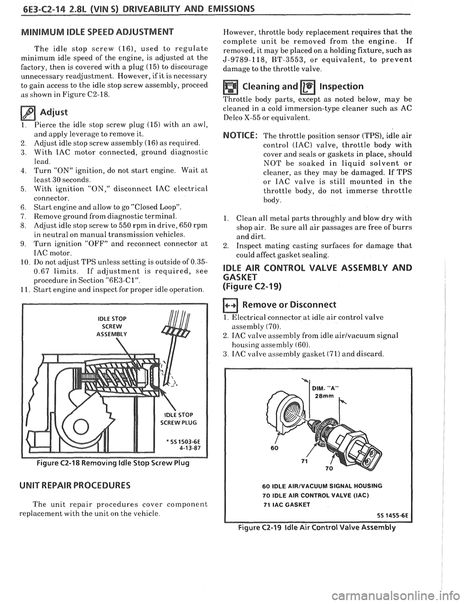
The idle stop screw (16), used to regulate
minimum idle speed of the engine, is adjusted at the
factory, then is covered with a plug
(15) to discourage
unnecessary readjustment. However,
if it is necessary
to gain access to the idle stop screw assembly, proceed
as shown in Figure C2-18.
Adjust
1. Pierce
the idle stop screw plug (15) with an awl,
and apply leverage to remove it.
2. Adjust idle
stop screw assembly (16) as required.
3. With IAC motor connected, ground diagnostic
lead.
4. Turn "ON" ignition, do not start engine. Wait at
least 30 seconds.
5. With ignition "ON," disconnect IAC electrical
connector.
6. Start engine and allow to go "Closed Loop".
7. Remove ground from diagnostic terminal.
8. Adjust idle stop screw to 550 rpm in drive, 650 rpm
in neutral on manual transmission vehicles.
9. Turn ignition "OFF7' and reconnect connector at
IAC motor.
10.
110 not adjust TPS unless setting is outside of 0.35-
0.67 limits. If adjustment is required, see
procedure in Section
"6l33-Cl".
11. Start engine and inspect for proper idle operation.
IDLE STOP
SCREW
ASSEtVIBLY
SCREW PLUG
* 55 1503-6E
Figure C2-18 Removing ldle Stop Screw Plug
UNIT REPAIR PROCEDURES
The unit repair procedures cover component
replacement with the unit on the vehicle. However,
throttle body replacement requires that the
complete unit be removed from the engine. If
removed, it may be placed on a holding fixture, such as
5-9789-118, BT-3553, or equivalent, to prevent
damage to the throttle valve.
Cleaning and Inspection
Throttle body parts, except as noted below, may be
cleaned in
a cold immersion-type cleaner such as AC
Delco X-55 or equivalent.
NOTICE: The throttle position sensor (TPS), idle air
control
(IAC) valve, throttle body with
cover and seals or gaskets in place, should
NOT be soaked in liquid solvent or
cleaner, as they may be damaged. If TPS
or IAC valve is still mounted in the
throttle body, do not immerse throttle
body.
1. Clean
all metal parts throughly and blow dry with
shop air. Be sure all air passages are free of burrs
and dirt.
2. Inspect mating casting surfaces for damage that
could affect gasket sealing.
IDLE AIR CONTROL VALVE ASSEMBLY AND
GASKET
(Figure
CZ-19)
Remove or Disconnect
1. Electrical connector at idle air control valve
assembly
(70).
2. IAC valve assembly from idle airlvacuum signal
housing assembly
(60).
3. IAC valve assembly gasket (71) and discard.
60 IDLE AIRIVACUUM SIGNAL HOUSING
70 IDLE AIR CONTROL VALVE
(IAC)
71 IAC GASKET
Figure C2-19 ldle Air Control Valve Assembly
Page 755 of 1825
6E3-C2-20 2.8L (VIN S) DRIVEABILITY AND EMISSIONS
AIR THROTTLE FLOW BODY
LD START VALVE
8-5 BLUNVHT
BLUIBLK
GRMNVHT
. GRNIBLK
ECM
.
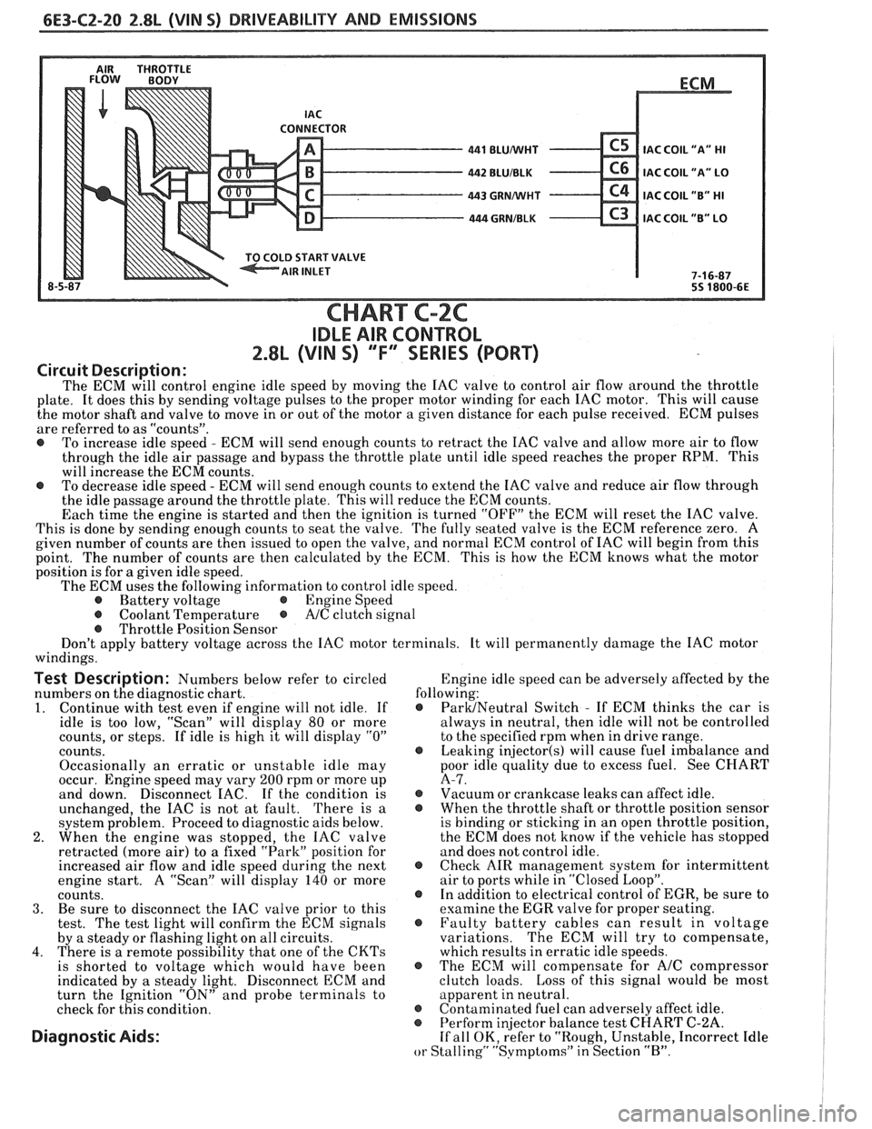
IAC COIL
"A" HI
IAC COIL "A" LO
IAC COIL "B" HI
C3 IAC COIL "B" LO
7-1 6-87
55 1800-6E
CHART C-2C
IDLE AIR CONTROL
2.8L (VIN S) ""F-SERIES (PORT)
Circuit Description:
The ECM will control engine idle speed by moving the IAC valve to control air flow around the throttle
plate. It does this by sending voltage pulses to the proper motor winding for each IAC motor. This will cause
the motor shaft and valve to move in or out of the motor a given distance for each pulse received. ECM pulses
are referred to as "counts".
@ To increase idle speed - ECM will send enough counts to retract the IAC valve and allow more air to flow
through the idle air passage and bypass the throttle plate until idle speed reaches the proper RPM. This
will increase the ECM counts.
@ To decrease idle speed - ECM will send enough counts to extend the IAC valve and reduce air flow through
the idle passage around the throttle plate. This will reduce the ECM counts.
Each time the engine is started and then the ignition is turned "OFF" the ECM will reset the IAC valve.
This is done by sending enough counts to seat the valve. The fully seated valve is the ECM reference zero. A
given number of counts are then issued to open the valve, and normal ECM control of IAC will begin from this
point. The
number of counts are then calculated by the ECM. This is how the ECM knows what the motor
position is for
a given idle speed.
The ECM uses the following information to control idle speed.
@ Battery voltage @ Engine Speed
@ Coolant Temperature @ A/C clutch signal
@ Throttle Position Sensor
Don't apply battery voltage across the IAC motor terminals. It will permanently damage the IAC motor
windings.
Test Description: Numbers below refer to circled Engine
idle speed can be adversely affected by the
numbers on the diagnostic chart. following:
1. Continue
with test even if engine will not idle. If @ ParUNeutral Switch - If ECM thinks the car is
idle is too low, "Scan" will display
80 or more always
in neutral, then idle will not be controlled
counts, or steps. If idle is high it will display
"0" to the specified rpm when in drive range.
counts.
@ Leaking injector(s) will cause fuel imbalance and
Occasionally an erratic or unstable idle may poor
idle quality due to excess fuel. See CHART
occur. Engine speed may vary
200 rpm or more up A-7.
and down. Disconnect
EAC. If the condition is @ Vacuum or crankcase leaks can affect idle.
unchanged, the IAC is not at fault. There is
a @ When the throttle shaft or throttle position sensor
system problem. Proceed to diagnostic aids below. is
binding or sticking in an open throttle position,
2. When the engine was stopped, the IAC valve the
ECM does not know if the vehicle has stopped
retracted (more air) to a fixed "Park" position for and does not control idle.
increased air flow and idle speed during the next
@ Check AIR management system for intermittent
engine start. A "Scan" will display
140 or more air
to ports while in "Closed Loop".
counts. @ In addition to electrical control of EGR, be sure to
3. Be sure to disconnect the IAC valve prior to this examine the
EGR valve for proper seating.
test. The test light will confirm the ECM signals @ Faulty battery cables can result in voltage
by a steady or flashing light on all circuits. variations. The
ECM will try to compensate,
4. There is a remote possibility that one of the CKTs which results in erratic idle speeds.
is shorted to voltage which would have been @ The ECM will compensate for A/C compressor
indicated by a steady light. Disconnect ECM and clutch
loads. Loss of this signal would be most
turn the Ignition "ON" and probe terminals to apparent
in neutral.
check for this condition.
@ Contaminated fuel can adversely affect idle. @ Perform in
or Stalling" "Svmptoms" in Section "B".
Page 761 of 1825
6E3-C3-4 2.8L (VIN S) DRIVEABILITY AND EMISSIONS
TO CANISTER
I.P. HARNESS CONNECTOR (FRONT VIEW)
428 DK GRNNEL
CHART C-3
CARIISXE PURGE VALVE CHECK
2.88 (VIN S) ""F4 SERIES (PORT)
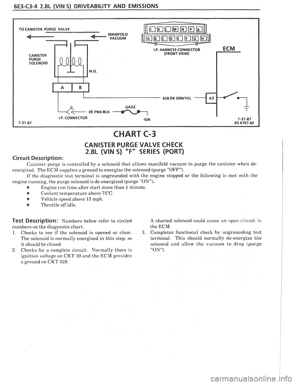
Circuit Description:
Canister purge is controlled by a solenoid that allows manifold vacuum to purge the canister when cle-
energized. The ECM supplies
a ground to energize the solenoid (purge "OFFJ').
If the diagnostic test terminal is ungrounded with the engine stopped or the following is met with the
engine running, the purge solenoid is de-energized (purge
"ON").
Engine run time after start more than 1 minute.
@ Coolant temperature above 75°C.
Vehicle speed above 15 mph.
@ Throttle off idle.
Test Description: Numbers below refer to circled
numbers on the diagnostic chart.
1. Checks to see if the solenoid is opened or close.
The solenoid is normally energized in this step;
so
it should be closed.
2. Checks for a complete circuit. Normally there is
ignition voltage on CKT
39 and the ECM provicles
a ground on CKT
428.
A shorted solenoid could cause an opet! circuit i11
the ECM.
3. Completes functional check by ungrounding test
terminal. This should normally de-energize the
solenoid
and allow the vacuum to drop (purge
"ON").
Page 779 of 1825
EXHAUST GAS VALVE OPEN
INTAKE AIR
171 VALVE CLOSED
VACUUM PORT
/ SPRING 4s 05366E
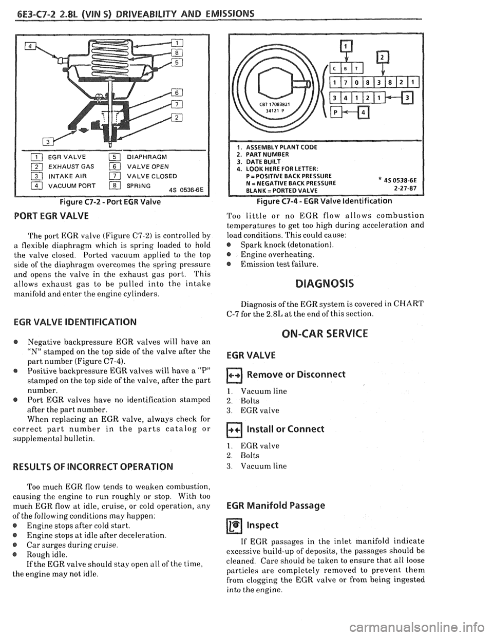
Figure C7-2 - Port EGR Valve
PORT EGR VALVE
The port EGR valve (Figure C7-2) is controlled by
a flexible diaphragm which is spring loaded to hold
the valve closed. Ported vacuum applied to the top
side of the diaphragm overcomes the spring pressure
and opens the valve in the exhaust gas port. This
allows exhaust gas to be pulled into the intake
manifold and enter the engine cylinders.
* 45 0538-6E 2-27-87
Figure C7-4 - EGR Valve Identification
Too little or no EGR flow allows combustion
temperatures to get too high during acceleration and
load conditions. This could cause:
@ Spark knock (detonation).
@ Engine overheating.
@ Emission test failure.
Diagnosis of the EGR system is covered in CHART
C-7 for the 2.8L at the end of this section.
EGR VALVE IDENTIFICATION
ON-CAR SERVICE @ Negative backpressure EGR valves will have an
"N" stamped on the top side of the valve after the
part number (Figure
C7-4).
Positive backpressure EGR valves will have a "P"
stamped on the top side of the valve, after the part
number.
@ Port EGR valves have no identification stamped
after the part number.
When replacing an EGR valve, always check for
correct part number in the parts catalog or
supplemental bulletin.
RESULTS OF INCORRECT OPERATION
Too much EGR flow tends to weaken combustion,
causing the engine to run roughly or stop. With too
much EGR flow at idle, cruise, or cold operation, any
of the following conditions may happen:
@ Engine stops after cold start.
e Engine stops at idle after deceleration.
@ Car surges during cruise.
@ Rough idle.
If the EGR valve should stay open
a11 of the time,
the engine may not idle.
EGR VALVE
Remove or Disconnect
1. Vacuum line
2. Bolts
3. EGRvalve
Install or Connect
1. EGR valve
2. Bolts
3. Vacuum line
EGR Manifold Passage
Inspect
If EGR passages in the inlet manifold indicate
excessive build-up of deposits, the passages should be
cleaned. Care should be taken to ensure that all loose
particles are completely removed to prevent them
from clogging the EGR valve or from being ingested
into the engine.