1988 PONTIAC FIERO stop start
[x] Cancel search: stop startPage 551 of 1825
6EZ-B-4 5.OL (VIN E) DRIVEABILITY AND EMISSIONS
DEWNATION 1 SPARK KNOCK
Definition: A mild to severe ping, usually worse under acceleration. The
engine makes sharp metallic knocks that change with throttle opening.
@ CHECK for obvious overheatingproblems. - For proper transmission shift points. See Section
- Low coolant. "7".
- Loose water pump belt. - TCC operation. See CHART C-8.
- Restricted air flow to radiator, or restricted - For incorrect basic engine parts such as cam,
water flow thru radiator. heads,
pistons, etc.
- Faulty or incorrect thermostat. - Excessive oil entering combustion chamber.
- Coolant sensor, which has shifted in value. @ Remove carbon with top engine cleaner. Follow
- Correct coolant solution - should be a 50150 instructions on can.
mix of GM
#lo52753 anti-freeze coolant (or @ If there is spray from only one injector, then there
equiv.) and water. is
a malfunction in the injector assembly, or in the
@ CHECK: signal to the injector assembly. The malfunction
- For poor fuel quality, proper octane rating. can be isolated by switching the injector
- For correct PROM. connectors. If the problem remains with the
- Spark plugs for correct heat range.
original injector, after switching the connector,
- ESC system opeation. See CHART C-5.
then the injector is defective. Replace the injector.
- Ignition timing. See Vehicle Emission Control
If the problem moves with the injector connector,
Information label. then the
problem is an improper signal in the
- Fuel system for low pressure. See CHART A-7.
injector circuits. See CHART A-3.
- Check EGR svstem. - CHART C-7.
HESITATION, SAG, STUMBLE
Definition: Momentary lack of response as the accelerator is pushed down.
Can occur at all car speeds.
C'sually most severe when first trying to make the car
move, as from a stop sign.
May cause the engine to stall if severe enough.
@ Perform careful visual (physical) check, as Information" label.
described at start of Section
"B". - Generator output voltage. Repair if less than 9 or
@ CHECK: more than 16 volts.
- Fuel pressure. See CHART A-7. - For open ignition system ground, CKT 453.
- Water contaminated fuel. - Canister purge system for proper operation. See
- TPS for binding or sticking.
Section "C3".
- Ignition timing. See "Emission Control - EGR valve operation, CHART C-7.
CU"F OUT, MISSES
Definition: Steady pulsation or jerking that follows engine
speed, usually more pronounced as engine load increases. The
exhaust has a steady spitting sound at idle or low speed.
@ Perform careful visual (physical) check, us
described at start of Section
"B".
@ If ignition system is suspected of causing a miss
at idle or cutting, out under load:
@ Check for missing cylinder by:
1. Disconnect IAC motor. Start engine.
Remove one spark plug wire at a time, using
insulated pliers.
2. If there is an rpm drop on all cylinders, (equal
to within 50
rpm), go to "Rough, Unstable, Or
Incorrect Idle, Or Stalling" symptom.
Reconnect
IAC motor.
3. If there is no rpm drop on one or more
cylinders, or excessive variation in drop, check
for spark, on the suspected
cylinder(s) with J
26792 (ST-1251 spark tester or equivalent. If no
spark, see Section
"6D" for "Intermittent Operation
or Miss". If there is spark, remove spark plug(s) in
these cylinders and check for:
- Cracks
- Wear
- Improper gap
- Burned electrodes
- Heavy deposits
- Perform compression check on
questionable cylinder.
@ Check wire resistance (shoulcl not exceed 30,000
ohms), also, check rotor and distributor cap.
Page 553 of 1825
6E2-8-6 5.OL (VIN E) DRIVEABILITY AND EMISSIONS
- MAP Sensor - Ignition "ON", engine stopped.
Compare MAP voltage with known good vehicle.
-
Voltage should be the same + 400 mV (.4 volts).
OR
Start and idle engine. Disconnect
sensor
electrical connector. If idle improves, substitute
a known good sensor and recheck.
- A/C refrigerant pressure too high. Check for
overcharge or faulty pressure switch.
- PCV valve for proper operation by placing finger
over inlet hole in valve end several times. Valve
should snap back. If not, replace valve.
Run a cylinder compression check See Section
" 6".
Inspect oxygen sensor for silicon contamination
from fuel, or use of improper RTV sealant. The
sensor will have a white, powdery coating, and
will result in a high but false signal voltage (rich
exhaust indication). The ECM will then reduce
the amount of fuel delivered to the engine,
causing a severe driveability problem.
EXCESSIVE EXHAUST EMISSIONS OR ODORS
Definition: Vehicle fails an emission test. Vehicle has excessive "rotten egg"
smell. Excessive odors do not necessarily indicate excessive emissions.
@ Perform "Diagnostic Circuit Check".
@ IF TEST SHOWS EXCESSIVE CO AND HC, (or
also has excessive odors)
@ Check items that will cause engine to run
RICH.
e Make sure engine is at normal operating
temperature.
o CHECK:
- Fuel pressure. See CHART A-7.
- Incorrect timing. See Vehicle Emission
Control Information label.
- Canister for fuel loading. See CHART C-3.
- PCV valve for being plugged, stuck or blocked
PCV hose or fuel in the crankcase.
- Spark plugs, plug wires, and ignition
components. See Section
"6D".
- Check for lead contamination of catalytic
converter (look for removal of fuel filler neck
restrictor).
- Check for properly installed fuel cap.
@ If the system is running rich, (block learn less
than
1181, refer to "Diagnostic Aids" on facing
page of Code
45.
o IF TEST SHOWS EXCESSIVE NOx:
@ Check items which cause car to run LEAN, or
to run too hot.
- EGR valve for not opening. See CHART C-7.
- Vacuum leaks. - Coolant system and coolant fan for proper
operation. See
CHART C-12.
- Remove carbon with top engine cleaner.
Follow instructions on can.
- Check ignition timing for excessive base
advance. See Emission Control Information
label.
@ If the system is running lean, (block learn greater
than
138) refer to "Diagnostic Aids" on facing
page of Code
44.
DIESELING, RUN-ON
Definition: Engine continues to run after key is turned "OFF", but runs very roughly.
Ifengine runs smoothly, check ignition switch and adjustment.
@ Check injector for leaking. Apply 12 volts to fuel Visually check injector and TBI assembly for fuel
pump test terminal to turn "ON" fuel pump and leakage.
pressurize fuel system.
BACKFIRE
Definition: Fuel ignites in intake manifold, making a loud popping noise.
@ CHECK: - For faulty spark plugs and/or plug wires or
- EGR operation for being open all the time. See
hoots.
CHART C-7. - Faulty A.I.R. check valve.
- Output voltage of ignition coil. @ Perform a compression check - look for sticking or
- For crossfire between spark plugs (distributor leaking valves.
cap, spark plug wires, and proper routing' of plug
- For proper valve timing.
wires).
- Broken or worn valve train parts.
- Engine timing - See Emission Control
Information label.
Page 586 of 1825
DRIVEABILITY AND EMISSIONS - 5.0L (VIN E) 6EZ-CZ-11
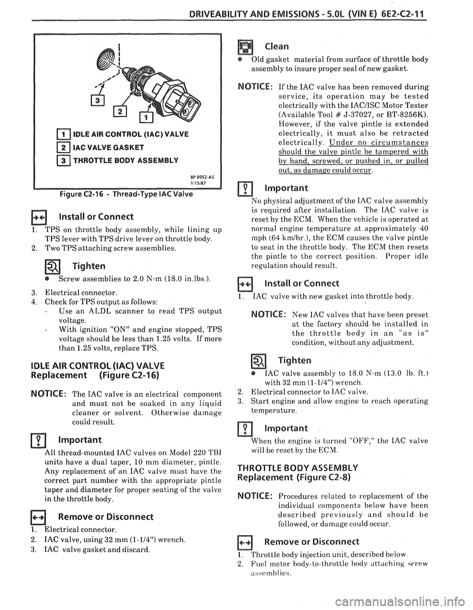
IDLE AIR CONTROL (IAC) VALVE
IAC VALVE GASKET
THROTTLE BODY ASSEMBLY
Figure C2-16 - Thread-Type IAC Valve
Install or Connect
1. TPS on throttle body assembly, while lining up
TPS lever with TPS drive lever on throttle body.
2. Two
TPS attaching screw assemblies.
Tighten
@ Screw assemblies to 2.0 N-m (18.0 in.lbs.).
3. Electrical connector.
4. Check for TPS output as follows: - Use an ALDL scanner to read TPS output
voltage.
- With ignition "ON" and engine stopped, TPS
voltage should be less than 1.25 volts. If more
than 1.25 volts, replace TPS.
IDLE AIR CONTROL (IAC) VALVE
Replacement (Figure CZ-16)
NOTICE:
The IAC valve is an electrical
component
and must not be soaked in any liquid
cleaner or solvent. Otherwise
damage
could result.
Important
All thread-mounted IAC valves on Model 220 TBI
units have a dual taper, 10 mm diameter, pintle.
Any replacement of an IAC valve must have the
correct part number with the appropriate pintle
taper and diameter for proper seating of the valve
in the throttle body.
Remove or Disconnect
1. Electrical connector.
2. IAC valve, using 32 mm (1-114") wrench.
3. IAC
valve gasket and discard.
Clean
@ Old gasket material from surface of throttle body
assembly to insure proper seal of new gasket.
NOTICE: If the IAC valve has been removed during
service, its operation may be tested
electrically with the
IACIISC Motor Tester
(Available Tool
# 5-37027, or BT-8256K).
However, if the valve pintle is extended
electrically, it must also be retracted
electrically. Under no circumstances
should the valve pintle be tampered with
by hand, screwed, or pushed in, or pulled
out, as damage could occur.
Important
No physical adjustment of the IAC valve assembly
is required after installation. The IAC valve is
reset by the ECM. When the vehicle is operated at
normal engine temperature at approximately 40
mph (64
kmlhr.), the ECM causes the valve pintle
to seat in the throttle body. The ECM then resets
the pintle to the correct position. Proper idle
regulation should result.
Install or Connect
1. IAC valve with new gasket into throttle body
NOTICE: New IAC valves that have been preset
at the factory should be installed in
the throttle
body in an "as is"
condition, without any adjustment.
Tighten
@ IAC valve assembly to 18.0 N.m (13.0 lb. ft.)
with 32 mm
(1-114") wrench.
2. Electrical connector to IAC valve.
3. Start engine and allow engine to reach operating
temperature.
Important
When the engine is turned "OFF," the IAC valve
will be reset by the ECM.
THROTTLE BODY ASSEMBLY
Replacement (Figure CZ-8)
NOTICE:
Procedures related to replacement of the
individual components below have been
described previously and should be
followed, or damage could occur.
Remove or Disconnect
1. Throttle body injection unit, described below
2. Fuel
meter body-to-throttle hodv attaching ~CI'PW
.i~~rmhlie
Page 587 of 1825
6E2-C2-12 DRIVEABILITY AND EMISSIONS - 5.0b (VIN E)
3. Fuel meter body assembly.
4. Throttle body-to-fuel meter body gasket. Discard
gasket.
a Disassemble
@ TPS from old throttle body, according to previous
instructions, for reuse on new throttle body. (New
IAC valve comes with new throttle body.)
Assemble
@ TPS onto replacement throttle body assembly,
according to previous instructions.
Install or Connect
1. New throttle body-to-fuel meter body gasket.
2. Fuel meter body assembly on throttle body
assembly.
3. Fuel meter body-throttle
body attaching screw
assemblies that have been coated with locking
compound.
Tighten
@ Attaching screw assemblies to 4.0 N.m
(35.0 Ib. in.).
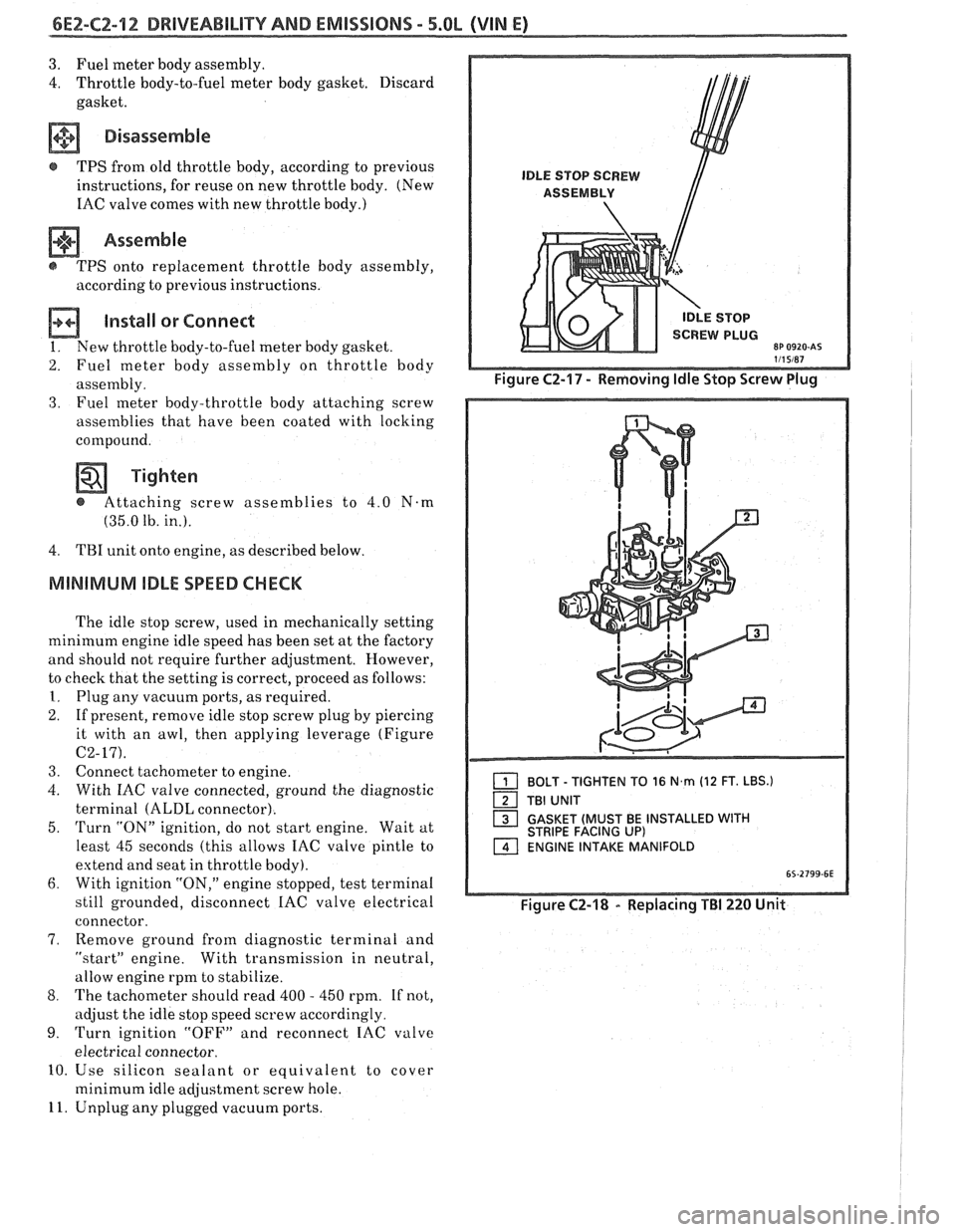
4. TBI
unit onto engine, as described below.
MllMiMhlM IDLE SPEED CHECK
The idle stop screw, used in mechanically setting
minimum engine idle speed has been set at the factory
and should not require further adjustment. However,
to check that the setting is correct, proceed as follows:
I. Plug any vacuum ports, as required.
2. If present, remove idle stop screw plug by piercing
it with an awl, then applying leverage (Figure
C2-17).
3. Connect tachometer to engine.
4. With IAC valve connected, ground the diagnostic
terminal
(ALDL connector).
5.
Turn "ON" ignition, do not start engine. Wait at
least 45 seconds (this allows IAC valve pintle to
extend and seat in throttle body).
6. With ignition "ON," engine stopped, test terminal
still grounded, disconnect
IAC valve electrical
connector.
7, Remove ground from diagnostic terminal and
"startJ' engine. With transmission in neutral,
allow engine rpm to stabilize.
8. The tachometer should read 400 - 450 rpm. If not,
adjust the idle stop speed screw accordingly.
9. Turn ignition "OFF" and reconnect IAC valve
electrical connector.
10. Use silicon sealant or equivalent to cover
minimum idle adjustment screw hole.
11. Unplug any plugged vacuum ports.
1 BOLT - TIGHTEN TO 16 N,rn (12 FT. LBS.)
TBI UNIT
1 GASKET (MUST BE INSTALLED WITH STRIPE FACING UP) ENGINE INTAKE MANIFOLD
Figure C2-18 - Replacing TBI 220 Unit
Page 591 of 1825
6E2-CZ-16 DRIVEABILITY AND EMISSIONS - 5.OL (WIN E)
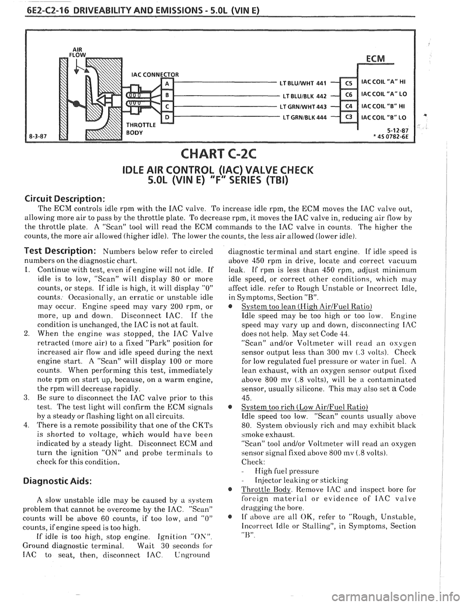
CHART C-2C
IDLE AIR CONTROL (IAC) VALVE CHECK
5.OL (VIN E) "F'" SERIES (TBI)
Circuit Description:
The ECM controls idle rprn with the IAC valve. To increase idle rpm, the ECM moves the IAC valve out,
allowing more air to pass by the throttle plate. To decrease rpm, it moves the IAC valve in, reducing air flow by
the throttle plate. A "Scan" tool will read the
ECM commands to the IAC valve in counts.
The higher the
counts, the more air allowed (higher idle). The lower the counts, the less air allowed (lower idle).
Test Description: Numbers below refer to circled
numbers on the diagnostic chart.
1. Continue with test, even if engine will not idle. If
idle is to low, "Scan" will display 80 or more
counts, or steps. If idle is high, it will display
"0"
counts. Occasionally, an erratic or unstable idle
may occur.
Engine speed may vary 200 rpm, or
more, up and down. Disconnect IAC. If the
condition is unchanged, the IAC is not at fault.
2. When the engine was stopped, the IAC Valve
retracted (more air) to a fixed "Park" position for
increased air flow and idle speed during the next
engine start. A "Scan" will display 100 or more
counts. When performing this test, immediately
note rprn on start up, because, on a warm engine,
the rprn will decrease rapidly.
3. Be sure to disconnect the IAC valve prior to this
test.
The test light will confirm the ECM signals
by
a steady or flashing light on all circuits.
4. There is a remote possibility that one of the
CKTs
is shorted to voltage, which would have been
indicated by a steady light. Disconnect ECM and
turn the ignition
"ON" and probe terminals to
check for this condition.
Diagnostic Aids:
A slow unstable idle may be caused by a system
problem that cannot be overcome by the
IAC. "Scan"
counts will be above 60 counts, if too low,
and "0"
counts, if engine speed is too high.
If idle is too high, stop engine. Ignition "Oh'".
Ground diagnostic terminal. Wait 30 seconds for
IAC to seat, then, disconnect IAC. Lnground
diagnostic terminal and start engine. If idle speed is
above 450 rprn in drive, locate and correct vacuum
leak. If rpm is less than 450 rpm,
ad,jrlst minimum
idle speed, or correct other conditions, which may
affect idle. refer to Rough Unstable or Incorrect Idle,
in Symptoms, Section
"R".
@ System too lean (Hi.gh AirJFuel Ratio)
Idle speed may be too high or too low. Engine
speed may vary up and down, disconnecting IAC
does not help. May set Code
33.
"Scan" and/or Voltmeter will read an oxygen
sensor output less than 300 mv
(.3 volts). Check
for low regulated fuel pressure or water in
fuel. A
lean exhaust, with an oxygen sensor outpirt fixed
above 800
mv (.8 volts), will be a contaminated
sensor, usually silicone. This may also set
a Code
45.
@ System too rich (Low AirIFuel Ratio)
Idle speed too low. "Scan" counts usually above
80. System obviously rich and may exhibit black
srnoke exhaust.
"Scan" tool and/or Voltmeter will
read an oxygen
sensor signal fixed above 800
mv (.8 volts).
Check:
- High fuel pressure
- Injector leaking or sticking
@ Throttle Body. Remove IAC and inspect bore for
foreign material or evidence of
IAC valve
dragging the bore.
@ If above ;
e all OK, refer to "Rough, Unstable,
Incorrect Idle or Stalling", in Symptoms, Section
"I<".
Page 597 of 1825
6E2-C3-4 5.OL (VIN E) DRIVEABILITY AND EMISSIONS
428 DK GRNNEL
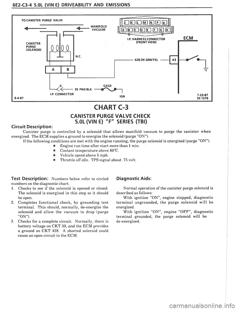
CHART C-3
CANlSTER PURGE VALVE CHECK
5.OL (VIN E) "F"' SERlES (TBI)
Circuit Description:
Canister purge is controlled by a solenoid that allows manifold vacuum to purge the canister when
energized. The ECM supplies a ground to energize the solenoid (purge "ON").
If the following conditions are met with the engine running, the purge solenoid is energized (purge "ON").
@ Engine run time after start more than 1 min.
@ Coolant temperature above 80°C.
Vehicle speed above
5 mph.
@ Throttle off idle. TPS signal about .75 volt.
Test Description: Numbers below refer to circled
numbers on the diagnostic chart.
I. Checks to see if the solenoid is opened or closed.
The solenoid is energized in this step so it should
be open.
2. Completes functional check,
by grounding test
terminal. This should, normally, de-energize the
solenoid and allow the vacuum to drop (purge
"ON").
3. Checks for
a complete circuit. Normally, there is
battery voltage on CKT 39, and the ECM provides
a ground on CKT 428.
A shorted sole~oid could
cause an open circuit in the ECM.
Diagnostic Aids:
Normal operation of the canister purge solenoid is
described as follows:
With ignition "ON", engine stopped, diagnostic
terminal ungrounded, the purge solenoid will be
energized. With ignition "ON", engine "OFF", diagnostic
terminal grounded, the purge solenoid will be
de-energized.
Page 621 of 1825
6E2-C7-2 DRlVEABlLlTV AND EMISSIONS - 5.OL
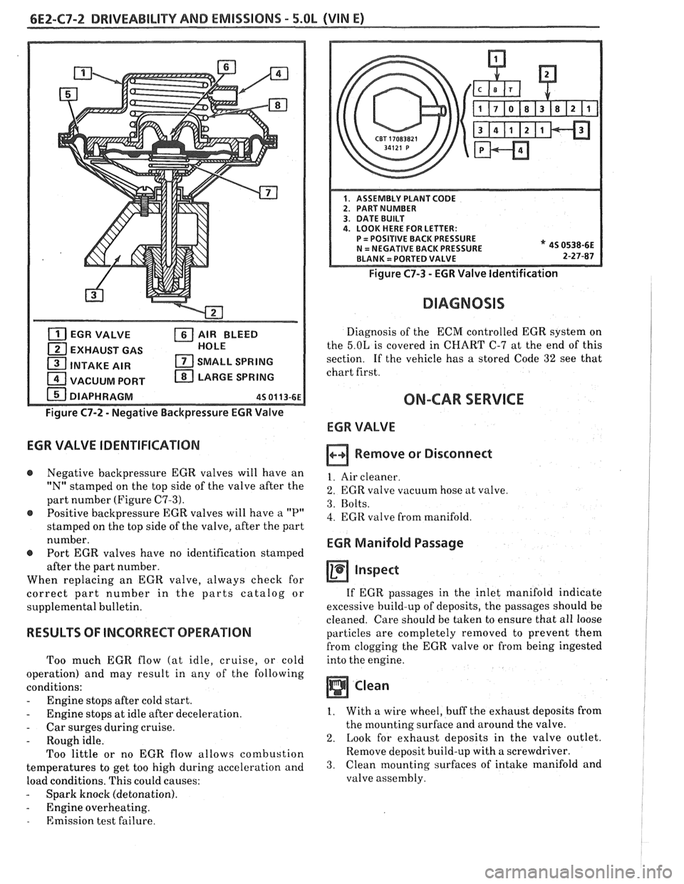
EGR VALVE AIR BLEED
EXHAUST GAS HOLE
1 INTAKE
AIR SMALL SPRING
1 VACUUM PORT LARGE SPRING
DIAPHRAGM
45 01 13-61
Figure C7-2 - Negative Backpressure EGR Valve
EGR VALVE IDENTIFICATION
@ Negative backpressure EGR valves will have an
"N" stamped on the top side of the valve after the
part number (Figure
C7-3).
@ Positive backpressure EGR valves will have a "P"
stamped on the top side of the valve, after the part
number.
@ Port EGR valves have no identification stamped
after the part number.
When replacing an EGR valve, always check for
correct part number in the parts catalog or
supplemental bulletin.
RESULTS OF INCORRECT OPERATION
Too much EGR flow (at idle, cruise, or cold
operation) and may result in any of the following
conditions:
- Engine stops after cold start.
- Engine stops at idle after deceleration.
- Car surges during cruise.
- Rough idle.
Too little or no EGR flow allows combustion
temperatures to get too high during acceleration and
load conditions. This could causes:
- Spark knock (detonation).
- Engine overheating.
- Emission test failure.
Figure C7-3 - EGR Valve Identification
DIAGNOSIS
Diagnosis of the ECM controlled EGR system on
the
5.OL is covered in CHART C-7 at the end of this
section. If the vehicle has
a stored Code 32 see that
chart first.
ON-CAR SERVICE
ECR VALVE
Remove or Disconnect
1. Air cleaner.
2. EGR valve vacuum hose at valve.
3. Bolts.
4. EGR valve from manifold.
EGR Manifold Passage
inspect
If EGR passages in the inlet manifold indicate
excessive build-up of deposits, the passages should be
cleaned. Care should be taken to ensure that all loose
particles are completely removed to prevent them
from clogging the EGR valve or from being ingested
into the engine.
Clean
1. With a wire wheel, buff the exhaust deposits from
the mounting surface and around the valve.
2. Look for exhaust deposits in the valve outlet.
Remove deposit build-up with a screwdriver.
3. Clean mounting surfaces of intake manifold and
valve assembly.
Page 671 of 1825
6E3-A-I8 2.8b (VIN 5) DRIVEABILITY AND EMISSIONS
PUMP INLET FILTER
IN-TANK PUMP
FUEL
PRESSURE CONNECTOR
CHART A-7
(Page 4 of 2)
FUEL SYSTEM DsAGNOSBS
2.8L (VIN S) ""FYSERBES (PORT)
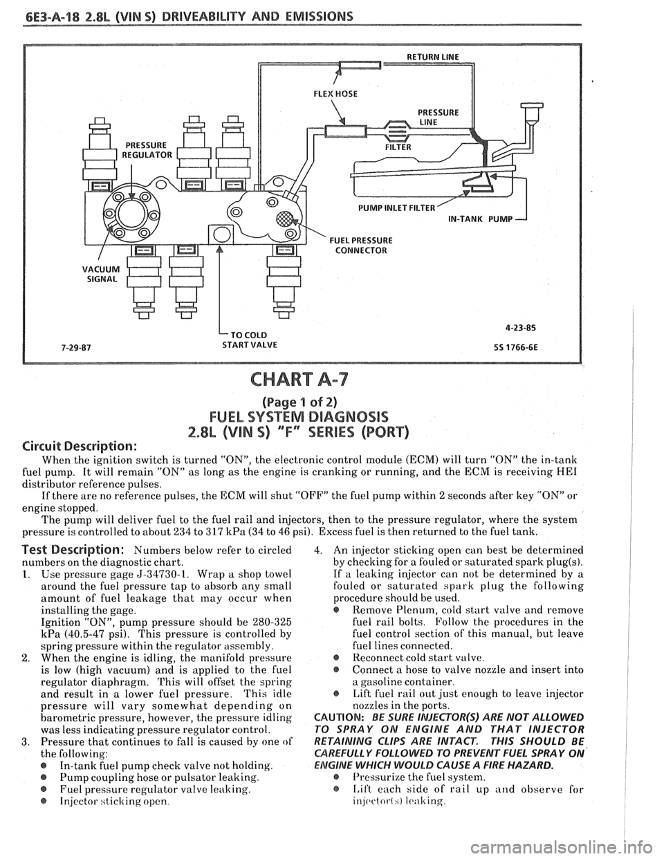
Circuit Description:
When the ignition switch is turned "ON", the electronic control module (ECM) will turn "ON" the in-tank
fuel pump. It will remain "ON" as long as the engine is cranking or running, and the ECM is receiving
HE1
distributor reference pulses.
If there are no reference pulses, the ECM will shut "OFF" the fuel pump within
2 seconds after key "ON" or
engine stopped.
The pump will deliver fuel to the fuel rail and injectors, then to the pressure regulator, where the system
pressure is controlled to about 234 to 317
kPa (34 to 46 psi). Excess fuel is then returned to the fuel tank.
Test Description: Numbers below refer to circled
numbers on the diagnostic chart.
1. Use pressure gage 5-34730-1. Wrap a shop towel
around the fuel pressure tap to absorb any small
amount of fuel leakage that
may occur when
installing the gage.
Ignition "ON", pump pressure should be 280-325
kPa (40.5-47 psi). This pressure is controlled by
spring pressure within the regulator assembly.
2. When the engine is idling, the manifold pressure
is low (high vacuum) and is applied to the fuel
regulator diaphragm. This will offset the spring
and result in a lower fuel pressure.
'This idle
pressure will vary somewhat depending on
barometric pressure, however, the pressure idling
was less indicating pressure regulator control.
3. Pressure that continues to fall is caused by one of
the following:
In-tank fuel pump check valve not holding.
@ Pump coupling hose or pulsator leaking.
Fuel pressure regulator valve leaking.
@ Injector sticking open. 4.
An injector sticking open can best be determined
by checking for a fouled or saturated spark
plug(s).
If a leaking injector can not be determined by a
fouled or saturated spark plug the following
procedure should be used.
e Remove Plenum, cold start valve and remove
fuel rail bolts. Follow the procedures in the
fuel control section of this manual, but leave
fuel lines connected.
@ Reconnect cold start valve.
@ Connect a hose to valve nozzle and insert into
a gasoline container.
@ Lift fuel rail out just enough to leave injector
nozzles in the ports.
CAUTION: BE SURE INJEePOR(S) ARE NOT ALLOWED
PO SPRAY ON ENGINE AND THAT INJECTOR
RETAINING
CLIPS ARE INTACT. PHIS SHOULD BE
CAREFULLY
FOLLOWD PO PREVENT FUEL SPRAY ON'
ElZIGlNE WHICH WOULD CAUSE A FIRE HAZARD.
@ Pressurize the fuel system.
@ I.if't each side of rail up and observe for
injc~ctot-l.) It.ulting