Page 1136 of 2389
INSPECTION OF EFI MAIN RELAY
1. INSPECT RELAY CONTINUITY
(a) Using an ohmmeter, check that there is continuity between
terminals 1 and 3.
(b) Check that there is no continuity between terminals 2
and 4.
If continuity is not as specified, replace the relay.
2. INSPECT RELAY OPERATION
(a) Apply battery voltage across terminals 1 and 3.
(b) Using an ohmmeter, check that there is continuity between
terminals 2 and 4.
If operation is not as specified, replace the relay.
± EFI SYSTEMElectronic Control System (EFI Main RelayFI±122
Page 1137 of 2389
INSPECTION OF CIRCUIT OPENING
RELAY
1. INSPECT RELAY CONTINUITY
(a) Using an ohmmeter, check that there is continuity
between terminals STA and E1.
(b) Check that there is continuity between terminals B
and FC.
(c) Check that there is no continuity between terminals B
and FP.
If continuity is not as specified, replace the relay.
2. INSPECT RELAY OPERATION
(a) Apply battery voltage across terminals STA and E1.
(b) Using an ohmmeter, check that there is continuity between
terminals B and FP.
(c) Apply battery voltage across terminals B and FC.
(d) Check that there is continuity between terminals B
and FP.
If operation is not as specified, replace the relay.
Circuit Opening Relay
± EFI SYSTEMElectronic Control System (Circuit Opening Relay)FI±123
Page 1142 of 2389
(b) Apply battery voltage across the terminals
(c) Check that air flows from pipe E to filter.
If operation is not as specified, replace the VSV. C. Inspect VSV operation
(a) Check that air flow from pipes E to G.
± EFI SYSTEMElectronic Control System (Fuel Pressure Control System))FI±128
Page 1147 of 2389
2. INSPECT VOLTAGE OF ECU
Check the voltage between each terminal of the wiring con-
nectors.
wTurn the ignition switch ON.
wMeasure the voltage at each terminal.
HINT:
wPerform all voltage measurements with the connectors
connected.
wVerify that the battery voltage is 11 V or more when the
ignition switch is ON.
Electronic Controlled Unit (ECU)
INSPECTION OF ECU
HINT: The EFI circuit can be checked by measuring the
resistance and voltage at the wiring connectors of the ECU.
1. (2VZ±FE)
PREPARATION (See page FI±50)
± EFI SYSTEMElectronic Control System (Electronic Controlled Unit
(ECU))FI±132
Page 1187 of 2389

ENGINE TUNE±UP
INSPECTION OF ENGINE COOLANT
(See steps 1 and 2 on page CO±4)
INSPECTION OF ENGINE OIL
(See steps 1 and 2 on page LU±6)
INSPECTION OF BATTERY
(See steps 1 and 2 on page CH±3)
Standard specific gravity:
1.25 ±1.27 when fully charged at 2O°C (68°F)
INSPECTION OF AIR FILTER
(See step 3 on page MA±5)
INSPECTION OF HIGH±TENSION CORDS
(See page IG±6 or 10)
Maximum resistance: 25 kW per cord
INSPECTION OF SPARK PLUGS (3S±FE)
(See page IG±6)
Correct electrode gap: 1.1 mm (0.043 in.)
Recommended spark plugs:
ND Q16R±U11
NGK BCPR5EY11
INSPECTION OF SPARK PLUGS (2VZ±FE)
(See page IG±10)
Correct electrode gap of new plug:
1.1 mm (0.043 in.)
Maximum electrode gap: 1.3 mm (0.051 in.)
Recommended spark plugs:
ND P020R
NGK BCPR6EP11
INSPECTION OF ALTERNATOR DRIVE BELT
(See step 3 on page CH±3)
Drive belt tension:
3S±FE w/ A/C New belt 175 +5 Ib
Used belt 130 +10 Ib
w/o A/C New belt 125 +25 Ib
Used belt 95 +20 Ib
2VZ±FE New belt 175 +5 Ib
Used belt 115 +20 Ib
± ENGINE MECHANICALEngine Tune±UpEM±10
Page 1199 of 2389

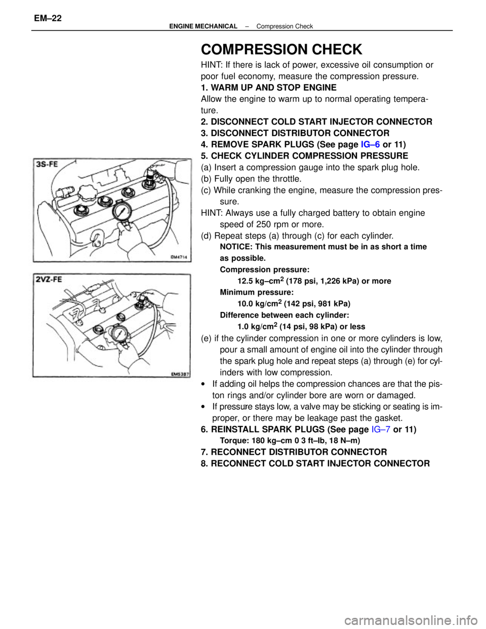
COMPRESSION CHECK
HINT: If there is lack of power, excessive oil consumption or
poor fuel economy, measure the compression pressure.
1. WARM UP AND STOP ENGINE
Allow the engine to warm up to normal operating tempera-
ture.
2. DISCONNECT COLD START INJECTOR CONNECTOR
3. DISCONNECT DISTRIBUTOR CONNECTOR
4. REMOVE SPARK PLUGS (See page IG±6 or 11)
5. CHECK CYLINDER COMPRESSION PRESSURE
(a) Insert a compression gauge into the spark plug hole.
(b) Fully open the throttle.
(c) While cranking the engine, measure the compression pres-
sure.
HINT: Always use a fully charged battery to obtain engine
speed of 250 rpm or more.
(d) Repeat steps (a) through (c) for each cylinder.
NOTICE: This measurement must be in as short a time
as possible.
Compression pressure:
12.5 kg±cm
2 (178 psi, 1,226 kPa) or more
Minimum pressure:
10.0 kg/cm
2 (142 psi, 981 kPa)
Difference between each cylinder:
1.0 kg/cm
2 (14 psi, 98 kPa) or less
(e) if the cylinder compression in one or more cylinders is low,
pour a small amount of engine oil into the cylinder through
the spark plug hole and repeat steps (a) through (e) for cyl-
inders with low compression.
wIf adding oil helps the compression chances are that the pis-
ton rings and/or cylinder bore are worn or damaged.
wIf pressure stays low, a valve may be sticking or seating is im-
proper, or there may be leakage past the gasket.
6. REINSTALL SPARK PLUGS (See page IG±7 or 11)
Torque: 180 kg±cm 0 3 ft±Ib, 18 N±m)
7. RECONNECT DISTRIBUTOR CONNECTOR
8. RECONNECT COLD START INJECTOR CONNECTOR
± ENGINE MECHANICALCompression CheckEM±22
Page 1200 of 2389
REMOVAL OF TIMING BELT
1. DISCONNECT CABLE FROM NEGATIVE TERMINAL
OF BATTERY
2. REMOVE RN FRONT WHEEL
3. REMOVE ENGINE RH UNDER COVER
4. REMOVE CRUISE CONTROL ACTUATOR
(See step 9 on page EM±108)
5. REMOVE DRIVE BELTS
6. REMOVE ALTERNATOR (See page CH±6)
7. REMOVE ALTERNATOR BRACKET
8. REMOVE RH MOUNTING STAY
(2WD)
Remove the three bolts and mounting stay.
TIMING BELT (3S±FE)
COMPONENTS
± ENGINE MECHANICALTiming Belt (3S±FE)EM±23
Page 1210 of 2389

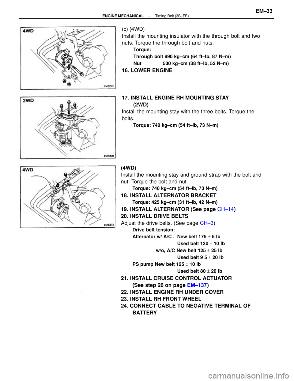
(4WD)
Install the mounting stay and ground strap with the bolt and
nut. Torque the bolt and nut.
Torque: 740 kg±cm (54 ft±Ib, 73 N±m)
18. INSTALL ALTERNATOR BRACKET
Torque: 425 kg±cm (31 ft±Ib, 42 N±m)
19. INSTALL ALTERNATOR (See page CH±14)
20. INSTALL DRIVE BELTS
Adjust the drive belts. (See page CH±3)
Drive belt tension:
Alternator w/ A/C . New belt 175 + 5 lb
Used belt 130 + 10 Ib
w/o, A/C New belt 125 + 25 Ib
Used belt 9 5 + 20 Ib
PS pump New belt 125 + 10 lb
Used belt 80 + 20 Ib
21. INSTALL CRUISE CONTROL ACTUATOR
(See step 26 on page EM±137)
22. INSTALL ENGINE RH UNDER COVER
23. INSTALL RH FRONT WHEEL
24. CONNECT CABLE TO NEGATIVE TERMINAL OF
BATTERY (c) (4WD)
Install the mounting insulator with the through bolt and two
nuts. Torque the through bolt and nuts.
Torque:
Through bolt 890 kg±cm (64 ft±Ib, 87 N±m)
Nut 530 kg±cm (38 ft±Ib, 52 N±m)
16. LOWER ENGINE
17. INSTALL ENGINE RH MOUNTING STAY
(2WD)
Install the mounting stay with the three bolts. Torque the
bolts.
Torque: 740 kg±cm (54 ft±lb, 73 N±m)
± ENGINE MECHANICALTiming Belt (3S±FE)EM±33