Page 1846 of 2389
REMOVAL OF DISTRIBUTOR
1. DISCONNECT CABLE FROM NEGATIVE TERMINAL
OF BATTERY
2. REMOVE AIR CLEANER HOSE
3. DISCONNECT DISTRIBUTOR CONNECTORS
4. DISCONNECT HIGH±TENSION CORDS FROM SPARK
PLUGS
5. REMOVE DISTRIBUTOR
Remove the two hold±down bolts and pull out the distributor.
Remove the 0±ring.
DISTRIBUTOR (3S±FE)
COMPONENTS
± IGNITION SYSTEMDistributor (3S±FE)IG±13
Page 1849 of 2389
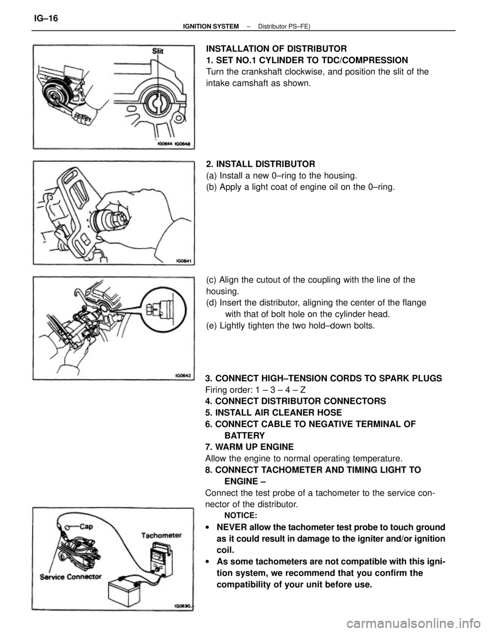
3. CONNECT HIGH±TENSION CORDS TO SPARK PLUGS
Firing order: 1 ± 3 ± 4 ± Z
4. CONNECT DISTRIBUTOR CONNECTORS
5. INSTALL AIR CLEANER HOSE
6. CONNECT CABLE TO NEGATIVE TERMINAL OF
BATTERY
7. WARM UP ENGINE
Allow the engine to normal operating temperature.
8. CONNECT TACHOMETER AND TIMING LIGHT TO
ENGINE ±
Connect the test probe of a tachometer to the service con-
nector of the distributor.
NOTICE:
wNEVER allow the tachometer test probe to touch ground
as it could result in damage to the igniter and/or ignition
coil.
wAs some tachometers are not compatible with this igni-
tion system, we recommend that you confirm the
compatibility of your unit before use. (c) Align the cutout of the coupling with the line of the
housing.
(d) Insert the distributor, aligning the center of the flange
with that of bolt hole on the cylinder head.
(e) Lightly tighten the two hold±down bolts. INSTALLATION OF DISTRIBUTOR
1. SET NO.1 CYLINDER TO TDC/COMPRESSION
Turn the crankshaft clockwise, and position the slit of the
intake camshaft as shown.
2. INSTALL DISTRIBUTOR
(a) Install a new 0±ring to the housing.
(b) Apply a light coat of engine oil on the 0±ring.
± IGNITION SYSTEMDistributor PS±FE)IG±16
Page 1858 of 2389
GENERAL REPAIR INSTRUCTIONS
1. Use fender seat and floor covers to keep the vehicle clean
and prevent damage.
2. During disassembly, keep parts in the appropriate order to
facilitate reassembly.
3. Observe the following:
(a) Before performing electrical work, disconnect the neg-
ative cable from the battery terminal.
(b) If it is necessary to disconnect the battery for inspection
or repair, always disconnect the cable from the nega-
tive H terminal which is grounded to the vehicle body.
(c) To prevent damage to the battery terminal post, loosen
the terminal nut and raise the cable straight up
without twisting or prying it.
(d) Clean the battery terminal posts and cable terminals
with a shop rag.
o not scrape them with a file or other
abrasive objects.
(e) Install the cable terminal to the battery post with
the nut loose, and tighten the nut after installation. Do
not use a hammer to tap the terminal onto the post.
(f) Be sure the cover for the positive (+) terminal is properly
in place.
4. Check hose and wiring connectors to make sure that they are
secure and correct.
5. Non±reusable parts
(a) Always replace cotter pins, gaskets, 0±rings and oil
seals etc. with new ones.
(b) Non±reusable parts are indicated in the component il-
lustrations by the ºrº symbol.
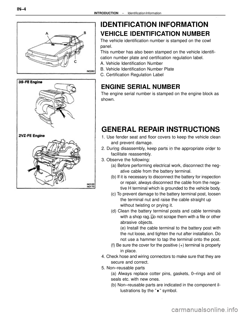
IDENTIFICATION INFORMATION
VEHICLE IDENTIFICATION NUMBER
The vehicle identification number is stamped on the cowl
panel.
This number has also been stamped on the vehicle identifi-
cation number plate and certification regulation label.
A. Vehicle Identification Number
B. Vehicle Identification Number Plate
C. Certification Regulation Label
ENGINE SERIAL NUMBER
The engine serial number is stamped on the engine block as
shown.
± INTRODUCTIONIdentification InformationIN±4
Page 1859 of 2389
GENERAL REPAIR INSTRUCTIONS
1. Use fender seat and floor covers to keep the vehicle clean
and prevent damage.
2. During disassembly, keep parts in the appropriate order to
facilitate reassembly.
3. Observe the following:
(a) Before performing electrical work, disconnect the neg-
ative cable from the battery terminal.
(b) If it is necessary to disconnect the battery for inspection
or repair, always disconnect the cable from the nega-
tive H terminal which is grounded to the vehicle body.
(c) To prevent damage to the battery terminal post, loosen
the terminal nut and raise the cable straight up
without twisting or prying it.
(d) Clean the battery terminal posts and cable terminals
with a shop rag.
o not scrape them with a file or other
abrasive objects.
(e) Install the cable terminal to the battery post with
the nut loose, and tighten the nut after installation. Do
not use a hammer to tap the terminal onto the post.
(f) Be sure the cover for the positive (+) terminal is properly
in place.
4. Check hose and wiring connectors to make sure that they are
secure and correct.
5. Non±reusable parts
(a) Always replace cotter pins, gaskets, 0±rings and oil
seals etc. with new ones.
(b) Non±reusable parts are indicated in the component il-
lustrations by the ºrº symbol.
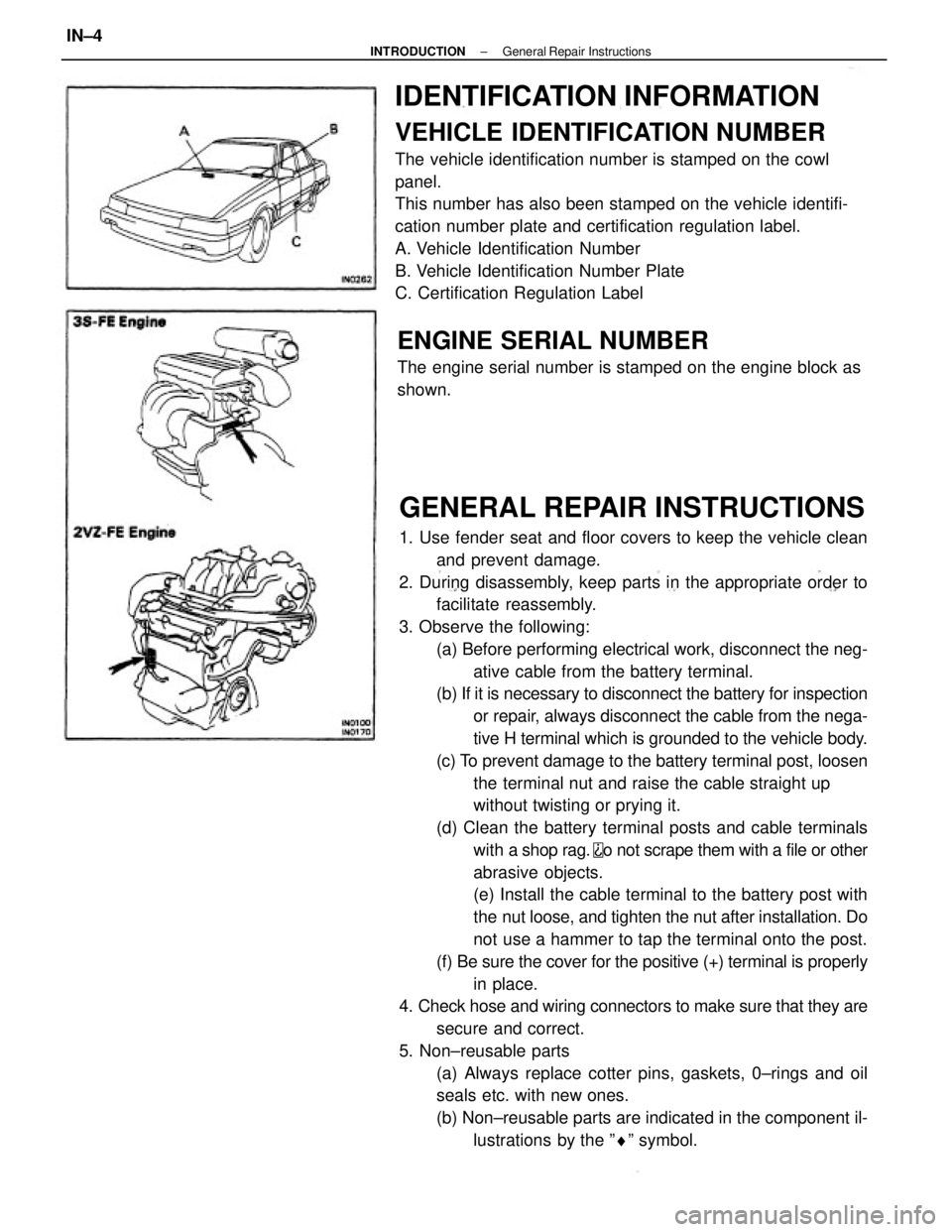
IDENTIFICATION INFORMATION
VEHICLE IDENTIFICATION NUMBER
The vehicle identification number is stamped on the cowl
panel.
This number has also been stamped on the vehicle identifi-
cation number plate and certification regulation label.
A. Vehicle Identification Number
B. Vehicle Identification Number Plate
C. Certification Regulation Label
ENGINE SERIAL NUMBER
The engine serial number is stamped on the engine block as
shown.
± INTRODUCTIONGeneral Repair InstructionsIN±4
Page 1863 of 2389
PRECAUTIONS FOR VEHICLES WITH AN
AUDIO SYSTEM WITH BUILT±IN ANTI±THEFT
SYSTEM
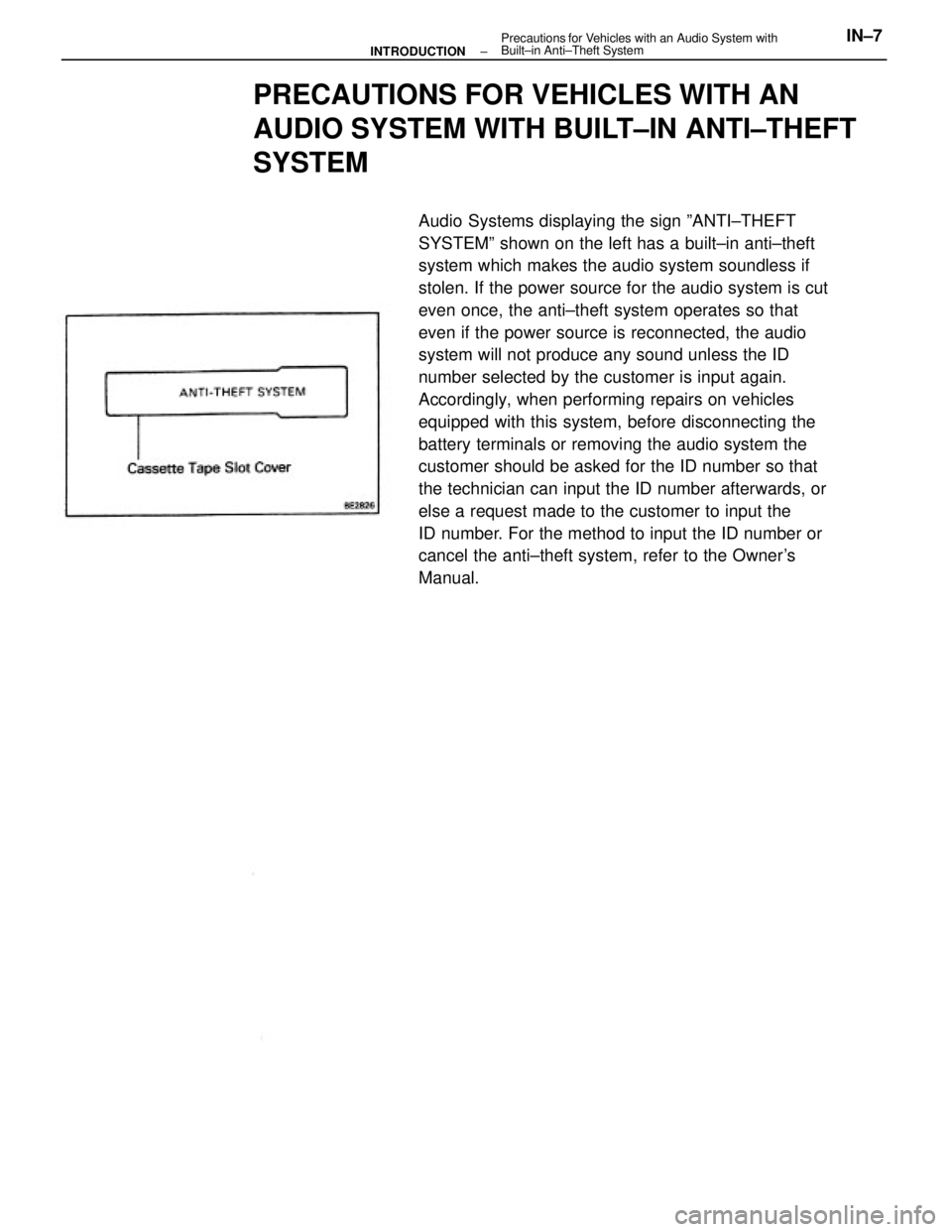
Audio Systems displaying the sign ºANTI±THEFT
SYSTEMº shown on the left has a built±in anti±theft
system which makes the audio system soundless if
stolen. If the power source for the audio system is cut
even once, the anti±theft system operates so that
even if the power source is reconnected, the audio
system will not produce any sound unless the ID
number selected by the customer is input again.
Accordingly, when performing repairs on vehicles
equipped with this system, before disconnecting the
battery terminals or removing the audio system the
customer should be asked for the ID number so that
the technician can input the ID number afterwards, or
else a request made to the customer to input the
ID number. For the method to input the ID number or
cancel the anti±theft system, refer to the Owner's
Manual.
± INTRODUCTIONPrecautions for Vehicles with an Audio System with
Built±in Anti±Theft SystemIN±7
Page 1915 of 2389
18. ACCELERATOR PEDAL
Check the pedal for smooth operation and uneven
pedal effort or catching.
19. CLUTCH PEDAL (See page CL±3)
Check the pedal for smooth operation.
Check that the pedal has the proper freeplay.
20. BRAKE PEDAL (See page BR±6)
(a) Check the pedal for smooth operation.
(b) Check that the pedal has the proper reserve
distance and freeplay.
(c) Check the brake booster function.
21. BRAKES
At a safe place, check that the brakes do not pull
to one side when applied.
22. PARKING BRAKE (See page BR±8)
(a) Check that the lever has the proper travel.
(b) On a safe incline, check that the vehicle is
held securely with only the parking brake
applied.
23. AUTOMATIC TRANSMISSION PARK
MECHANISM
(a) Check the lock release button of the selector
lever for proper and smooth operation.
(b) On a safe incline, check that vehicle is held
securely with the selector lever in the ºPº
position and all brakes released.
UNDER HOOD
24. WINDSHIELD WASHER FLUID
Check that there is sufficient fluid in the tank.
25. ENGINE COOLANT LEVEL
Check that the coolant level is between the
ºFULLº and ºLOWº lines on the see±through reser-
voir.
26. RADIATOR AND HOSES
(a) Check that the front of the radiator is clean
and not blocked with leaves, dirt or bugs.
(b) Check the hoses for cracks, kinks, rot or
loose connections.
27. BATTERY ELECTROLYTE LEVEL
Check that the electrolyte level of all battery cells
is between the upper and lower level lines on the
case. If level is low, add distilled water only.28. BRAKE AND CLUTCH FLUID LEVELS
(a) Check that the brake fluid level is near the
upper level line on the see±through reser-
voir.
(b) Check that the clutch fluid level is within
+ 5 mm (0.20 in.) of the reservoir hem.
29. ENGINE DRIVE BELTS
Check all drive belts for fraying, cracks, wear or
oiliness.
30. ENGINE OIL LEVEL
Check the level on the dipstick with the engine
turned off.
31. POWER STEERING FLUID LEVEL
Check the level.
The level should be in the ºHOTº or ºCOLDº
range depending on the fluid temperature.
32. AUTOMATIC TRANSMISSION FLUID
LEVEL
(a) Park the vehicle on a level surface.
(b) With the engine idling and the parking
brake applied, shift the selector into all
positions from ºPº to ºLº, and then shift
into ºPº.
(c) Pull out the dipstick and wipe off the fluid
with a clean rag. Re±insert the dipstick
and check that the fluid level is in the HOT
range.
(d) Perform this check with the fluid at normal
driving temperature (70 ± 80
°C or
158 ± 176°F).
NOTE: Wait about 30 minutes before check-
ing the fluid level after extended driving at high
speeds i n hot weather, driving i n heavy traffic
or with a trailer.
33. EXHAUST SYSTEM
Visually inspect for cracks, holes or loose sup-
ports.
If any change in the sound of the exhaust oK
smell of the exhaust fumes is noticed, have the
cause located and corrected.
± MAINTENANCEGeneral MaintenanceMA±17
Page 1932 of 2389
7. REMOVE TRANSAXLE MOUNTING BOLTS OF
TRANSAXLE UPPER
8. RAISE VEHICLE
NOTICE: Be sure the vehicle is securely supported.
9. REMOVE UNDER COVERS
10. DRAIN OUT FLUID
11. DISCONNECT SPEEDOMETER CABLE
S51 TRANSMISSION
REMOVAL OF TRANSAXLE
1. REMOVE NEGATIVE BATTERY CABLE
2. REMOVE CLUTCH RELEASE CYLINDER AND TUBE
CLAMP
5. REMOVE STARTER
(a) Disconnect the cable and connector.
(b) Remove the starter with the two bolts.
6. DISCONNECT BACK±UP LIGHT SWITCH
CONNECTOR AND GROUND STRAP 3. REMOVE±.CLUTCH TUBE BRACKET
(a) Remove the retainer from the bracket.
(b) Remove the bolt and bracket.
4. DISCONNECT CONTROL CABLES
(a) Remove the clips and washers.
(b) Remove the retainer from the cables.
± MANUAL TRANSAXLES51 TransmissionMT±4
Page 1954 of 2389
17. INSTALL CLUTCH RELEASE CYLINDER AND TUBE
CLAMP
18. INSTALL NEGATIVE BATTERY CABLE
19. CHECK FRONT WHEEL ALIGNMENT
(See page FA ± 3)
20. PERFORM ROAD TEST
Check for any abnormal noise or operation. 16. INSTALL CLUTCH TUBE BRACKET
(a) Install the bracket with a bolt.
(b) Install the retainer to the bracket.
± MANUAL TRANSAXLES51 TransmissionMT±40