Page 639 of 2389
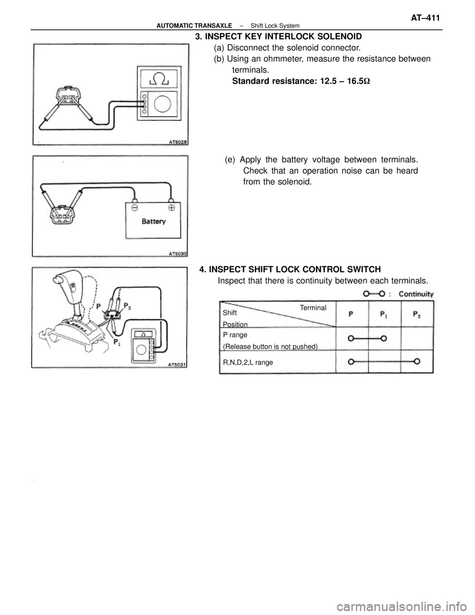
3. INSPECT KEY INTERLOCK SOLENOID
(a) Disconnect the solenoid connector.
(b) Using an ohmmeter, measure the resistance between
terminals.
Standard resistance: 12.5 ± 16.5�
(e) Apply the battery voltage between terminals.
Check that an operation noise can be heard
from the solenoid.
4. INSPECT SHIFT LOCK CONTROL SWITCH
Inspect that there is continuity between each terminals.
P range
(Release button is not pushed)
R,N,D,2,L range Shift
PositionTerminal
± AUTOMATIC TRANSAXLEShift Lock SystemAT±411
Page 787 of 2389
 Disconnect the connector from the seat belt warning
relay and ground the terminal 5 on the wire harness
side")
Seat Belt Warning
INSPECTION OF SEAT BELT WARNING
1. INSPECT WARNING LIGHT OPERATION
(a) Disconnect the connector from the seat belt warning
relay and ground the terminal 5 on the wire harness
side.
(b) Turn the ignition switch ON, check that the warning
light lights.
If warning light does not light, test the bulb.
2. INSPECT BUCKLE SWITCH OPERATION
(a) Disconnect the connector from the switch.
(b) Check that there is no continuity between terminals
on the switch side connector with the belt fastened.
(c) Check that there is continuity between terminals on
the switch side connector with the belt unfastened.
If operation is not as specified, replace the seat belt inner.
3. INSPECT UNLOCK WARNING SWITCH OPERATION
(See page BE±1 3)
If operation is not as specified, replace the switch.
4. INSPECT SEAT BELT WARNING RELAY CIRCUIT
Disconnect the relay connector and inspect the connector
on the wire harness side as shown in the chart.
Unlock warning switch OFF (Ignition key removed)
If circuit is as specified, replace the relay.
Unlock warning switch ON (Ignition key set)
Buckle switch ON (Seat belt unfastened)Buckle switch OFF (Seat belt fastened)Courtesy switch ON (Door opened)
Turn ignition switch to OFF or ACCTurn ignition switch to OFF or ACC Courtesy switch OFF (Door closed)
Turn ignition switch ONTurn ignition switch ON
6 ± Ground
Tester
connectionSpecified value
Battery voltage
Battery voltage
Battery voltageBattery voltage
No continuity 1 ± Ground
2 ± Ground
3 ± Ground
5 ± Ground4 ± GroundContinuity
Continuity
ContinuityNo voltageNo voltageNo voltage
No voltage
Continuity Condition
Check for
VoltageVoltage
Always
± BODY ELECTRICAL SYSTEMCombination MeterBE±41
Page 805 of 2389

HINT: When the relay circuit is as specified, inspect the
door lock signal.
(a) Connect the connector to the relay.
(b) Connect the positive (+) lead from the voltmeter")
(Door Lock Signal)
HINT: When the relay circuit is as specified, inspect the
door lock signal.
(a) Connect the connector to the relay.
(b) Connect the positive (+) lead from the voltmeter
to terminal 3 and the negative (±) lead to the ter-
minal 4.
(c) Set the door lock manual switch to UNLOCK,
check
that the voltage rises from 0 volts to battery volt-
age for approximately 0.2 seconds.
Door Lock Control Relay
INSPECTION OF RELAY
(Relay Circuit)
Disconnect the connector from the relay and inspect the
connector on the wire harness side as shown in the chart.
If circuit is as specified, inspect the door lock signal.
OFF or lock
(Door key free or turned to lock)
Passenger's door courtesy
switch positionPassenger's ±door lock
switch positionDriver's door courtesty
switch position
Unlock (Door key turned to unlock) Door key lock and unlock
switch position Key unlock warning
switch positionOFF (Ignition key removed)
Door lock manual
switch position
Door lock manual
switch positionDriver's door lock
switch position
Ignition switch
positionON (ignition key set) ON (Door unlocked)
ON (Door unlocked) ON (Door opened)
Tester connection
OFF (Door locked)
ON (Door opened)OFF (Door locked)
OFF (Door closed)OFF (Door closed)Specified value
No continuity
Battery voltage Battery voltage OFF or UnlockNo continuity
No continuityNo continuity
No continuity
No continuity
No continuityNo continuity
Continuity OFF or Lock
No voltageContinuityContinuity
Continuity ContinuityContinuity
ContinuityContinuityContinuity
ACC or ON Continuity
ConditionCheck for
ConstantConstant
VoltageUnlock
LOCKLock
± BODY ELECTRICAL SYSTEMDoor Lock Control SystemBE±59
Page 812 of 2389
 Disconnect the computer connector and inspect the
connector on the wire harness side as shown in the
chart.
Automatic Shoulder Belt
Switc")
Computer
INSPECTION OF COMPUTER
INSPECT COMPUTER CIRCUIT
(a) Disconnect the computer connector and inspect the
connector on the wire harness side as shown in the
chart.
Automatic Shoulder Belt
Switch and Right Rear Limit
Switch
(Passenger's side)
Automatic Shoulder Belt
Switch and Left Front Limit
Switch
(Driver's side)
Automatic Shoulder Belt
Switch and Left Rear Limit
Switch
(Driver's side)Automatic Shoulder Belt
Switch and Right Front
Limit Switch
(Passenger's side)w/o Power door lock
Courtesy Switch
(Driver's side)
Unlock Warning Switch
Open RH front door and set shoulder
anchor at ex. front end position.
Close LH front door and/or set shoulder
anchor at front end position.Close RH front door and/or set shoulder
anchor at front end position.Close RH front door and set shoulder
anchor at ex. rear end position.
Open R H front door and set and/or
shoulder anchor at rear end position.
Open LH front door and set shoulder
anchor at ex. front end position.
Open LH front door and set and/or
shoulder anchor at rear end position.Close LH front door and set shoulder
anchor at ex. rear end position.
If circuit is as specified, replace the comput-
er.
Close driver's side door and/or
remove ignition key. Open driver's side door and set
ignition key. w/ Power door lock
Courtesy Switch (Driver's side)Push Down Release Lever
Warning Light
w/ Power door lock
Unlock Warning Switch
Release spool release lever.Pull up spool release lever.Turn ignition switch ON.
Seat Belt Warning LightTurn ignition switch OFF.
Turn ignition switch OFF.Turn ignition switch OFF.
Turn ignition switch ON.Turn ignition switch ON.
Buckle Switch
(Driver's side)Spool Release SwitchRemove ignition key. Tester
connection
Unfasten lap belt.
Specified
value
Set ignition key.
Battery voltage Ignition Switch
Battery voltage Battery voltage
Battery voltage
Fasten lap belt. Circuit Breaker
No continuity
No continuityNo continuity
No continuity No continuity
No continuity
No continuity
No continuity 15 ± Ground
No continuity 11 ± Ground 10 ± Ground
12 ± Ground
16 ± Ground
18 ± Ground13 ± Ground
17 ± GroundOpen door. Check item
7 ± Ground4 ± Ground
9 ± Ground7 ± Ground2 ± Ground
5 ± Ground Motor (RH)
Motor (Lh#)
Continuity
ContinuityNo voltage No voltage
No vohage Continuity
Continuity Continuity
ContinuityContinuity Continuity
Continuity
ContinuityContinuity Check for
Continuity ContinuityContinuity
Continuity Close door.
Continuity
ContinuityContinuityContinuity
ContinuityContinuity
Continuity
ContinuityContinuity
Condition
Voltage Voltage
VoftageVoltageAlways
AlwaysAlways
Always
Ground1±3
s±8
± BODY ELECTRICAL SYSTEMAutomatic Shoulder BeltBE±66