Page 212 of 2389

4. The liquid refrigerant is charged by the expansion valve into a low temperature, low pressure liquid and
geseous mixture.
5. This cold and foggy refrigerant flows to the evaporator. Vaporizing the liquid in the evaporator, the heat
from the warm air stream passing through the evaporator core is transfered to the refrigerant.
All the liquid is changed into geseous refrigerant in the evaporator and only heat±laden geseous refrig-
erant is drawn into the compressor. Then the process is repeated again.
GENERAL DESCRIPTION
REFRIGERATION CYCLE
1. The compressor discharges high temperature and high pres-
sure refrigerant containing the heat absorbed from the
evaporator plus the heat created by the compressor in a dis-
charge stroke.
2. This gaseous refrigerant flows into the condenser. In the con-
denser, the gaseous refrigerant condenses into liquid
refrigerant.
3. This liquid refrigerant flows into the receiver which stores and
filters the liquid refrigerant till the evaporator requires the ref±
rigerant.
± AIR CONDITIONING SYSTEMAIR CONDITIONING SYSTEM General DescriptionAC±13
Page 217 of 2389

Discharging of Refrigeration System
Evacuating and Charging of
Refrigeration System
(See Air Conditioning Fundamentals and Repairs Pub. No.
36950E)
Condenser clogged
Drive belt slipping
Magnetic clutch faulty
Compressor faulty
Expansion valve faulty
Thermistor faulty
A/C amplifier faulty
Insufficient or too much refrigerant
Air or excessive compressor oil in
system
Receiver clogged
Water valve cable set faultyCheck condenser .
Check or replace drive belt
Check magnetic clutch
Check compressor
Check expansion valve
Check thermistor
Check amplifier
Check refrigerant volume
Evacuate and charge system
Evaporator clogged or frosted
Air leakage from cooling unit or air duct
Air inlet blocked
Blower motor faulty
A/C amplifier faulty
Drive belt slipping
Revolution detecting sensor faulty
(w/Power steering)
A/C amplifier faultyAC±33
AC±21
AC±23
AC±23
AC±39
AC±43
AC±45 to 47
AC±22
Repair as necessary
Replace blower motor
Check amplifierClean evaporator fins or filters
Repair as necessary
Check or replace drive belt
Check sensor
Check receiver
Reset water valve cable
A/C switch
indicator
flashingInsufficient
velocity of cool
airAC±41
AC±39 to 42 Insufficient
cooling
Check amplifier Possible cause
AC±21
AC±24AC±32
BE±79
AC±39 to 42
AC±45 to 47
AC±45 to 47 Remedy ProblemPage
± AIR CONDITIONING SYSTEMTroubleshooting Refrigeration SystemAC±17
Page 255 of 2389
VACUUM SWITCHING VALVE (VSV)
(See pages AC±4 to AC±7)
INSPECTION OF VSV
1. REMOVE VSV
2. CHECK VACUUM CIRCUIT CONTINUITY IN VSV 8*
BLOWING AIR INTO PIPE
(a) Connect the VSV terminals to the battery terminals
as shown.
(b) Blow into pipe ºAº, and check that air comes out of
pipe ºBº but does not come out of filter ºCº.
4. CHECK FOR OPEN CIRCUIT
Using an ohmmeter, measure the resistance between the
two terminals of the VSV.
Specified resistance: 37 ± 44
� at 20°C (68°F)
If resistance value is not as specified, replace the VSV. 3. CHECK FOR SHORT CIRCUIT
Using an ohmmeter, check that there is no continuity be-
tween each terminal and the VSV body.
If a short circuit is found, repair or replace the VSV.(c) Disconnect the battery.
(d) Blow into pipe ºAº and check that air comes out
of filter ºCº but does not come out of pipe ºBº.
If a problem is found, replace the VSV.
± AIR CONDITIONING SYSTEMVacuum Switching Valve (VSV)AC±48
Page 518 of 2389
(b) Using a filter gauge, check the pack clearance of the first and
reverse brake.
Clearance: A540E
0.85 ± 2.05 mm (0.033 ± 0.081 in.)
A540H
1.04 ± 2.16 mm (0.041 ± 0.085 in.)
If the pack clearance is not within specification, disassemble
and inspect. 43. CHECK FIRST AND REVERSE BRAKE
(a) Check the operation of the first and reverse brake piston
Apply compressed air into the case passage and confirm
that the piston moves.
If the piston does not move, disassemble and inspect. 42. REMOVE REAR PLANETARY RING GEAR
(a) Remove the rear planetary ring gear.
(b) Remove the bearing from the ring gear.
44. REMOVE FLANGE, DISCS AND PLATES OF FIRST
AND REVERSE BRAKE
(a) Remove the snap ring.(c) Remove the thrust washer from the rear planetary
gear.
± AUTOMATIC TRANSAXLERemoval of Component Parts (A540E and A540H)AT±251
Page 1024 of 2389

TROUBLESHOOTING
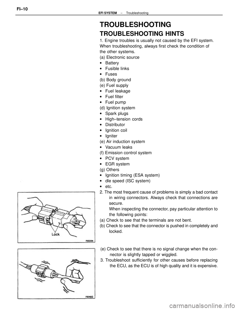
TROUBLESHOOTING HINTS
1. Engine troubles is usually not caused by the EFI system.
When troubleshooting, always first check the condition of
the other systems.
(a) Electronic source
wBattery
wFusible links
wFuses
(b) Body ground
(e) Fuel supply
wFuel leakage
wFuel filter
wFuel pump
(d) Ignition system
wSpark plugs
wHigh±tension cords
wDistributor
wIgnition coil
wIgniter
(e) Air induction system
wVacuum leaks
(f) Emission control system
wPCV system
wEGR system
(g) Others
wIgnition timing (ESA system)
wdle speed (ISC system)
wetc.
2. The most frequent cause of problems is simply a bad contact
in wiring connectors. Always check that connections are
secure.
When inspecting the connector, pay particular attention to
the following points:
(a) Check to see that the terminals are not bent.
(b) Check to see that the connector is pushed in completely and
locked.
(e) Check to see that there is no signal change when the con-
nector is slightly tapped or wiggled.
3. Troubleshoot sufficiently for other causes before replacing
the ECU, as the ECU is of high quality and it is expensive.
± EFI SYSTEMTroubleshootingFI±10
Page 1026 of 2389

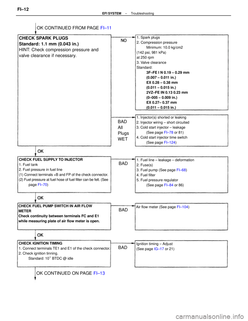
1. Spark plugs
2. Compression pressure
Minimum: 10.0 kg/cm2
(142 psi, 981 kPa)
at 250 rpm
3. Valve clearance
Standard:
3F±FE I N 0.19 ± 0.29 mm
(0.007 ± 0.011 in.)
EX 0.28 ± 0.38 mm
(0.011 ± 0.015 in.)
2VZ±FE IN 0.13 0.23 mm
(0±005 ± 0.009 in.)
EX 0.27± 0.37 mm
(0.011 ± 0.015 in.)
CHECK FUEL SUPPLY TO INJECTOR
1. Fuel tank
2. Fuel pressure in fuel line
(1) Connect terminals +B and FP of the check connector.
(2) Fuel pressure at fuel hose of fuel filter can be felt. (See
page FI±70)
CHECK IGNITION TIMING
1. Connect terminals TE1 and E1 of the check connector.
2. Check ignition tinning.
Standard: 10° BTDC @ idle CHECK FUEL PUMP SWITCH IN AIR FLOW
METER
Check continuity between terminals FC and E1
while measuring plate of air flow meter is open.1. Fuel line ± leakage ± deformation
2. Fuse(s)
3. Fuel pump (See page FI±68)
4. Fuel filter
5. Fuel pressure regulator
(See page FI±84 or 86) 1. Injector(s) shorted or leaking
2. Injector wiring ± short circuited
3. Cold start injector ± leakage
(See page FI±78 or 81)
4. Cold start injector time switch
(See page FI±124)CHECK SPARK PLUGS
Standard: 1.1 mm (0.043 in.)
HINT: Check compression pressure and
valve clearance if necessary.
Ignition timing ± Adjust
(See page IG±17 or 21)
OK CONTINUED FROM PAGE FI±11
OK CONTINUED ON PAGE FI±13
Air flow meter (See page FI±104)
BAD
All
Plugs
WET
BAD
BADBAD
± EFI SYSTEMTroubleshootingFI±12
Page 1027 of 2389

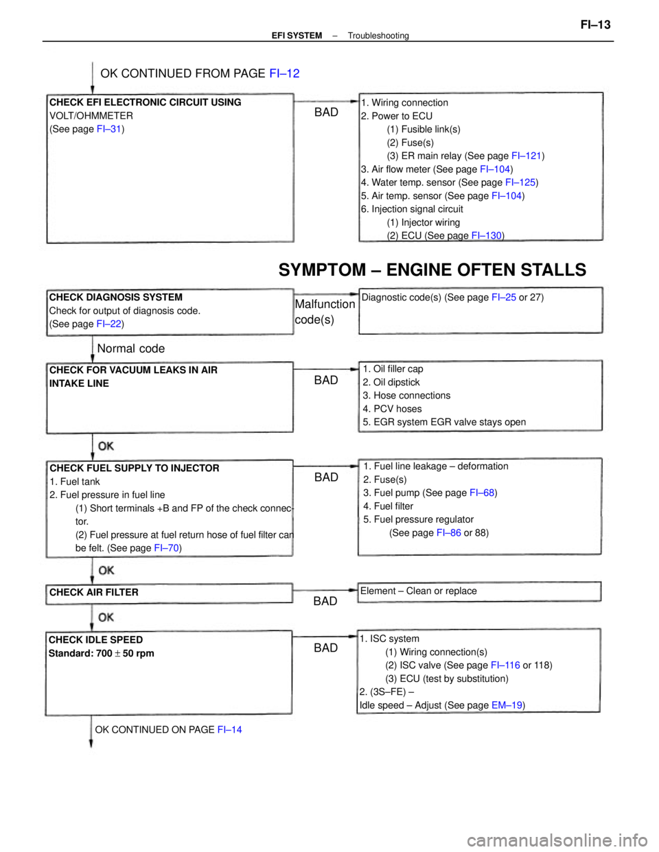
1. Wiring connection
2. Power to ECU
(1) Fusible link(s)
(2) Fuse(s)
(3) ER main relay (See page FI±121)
3. Air flow meter (See page FI±104)
4. Water temp. sensor (See page FI±125)
5. Air temp. sensor (See page FI±104)
6. Injection signal circuit
(1) Injector wiring
(2) ECU (See page FI±130)
CHECK FUEL SUPPLY TO INJECTOR
1. Fuel tank
2. Fuel pressure in fuel line
(1) Short terminals +B and FP of the check connec-
tor.
(2) Fuel pressure at fuel return hose of fuel filter can
be felt. (See page FI±70)
1. ISC system
(1) Wiring connection(s)
(2) ISC valve (See page FI±116 or 118)
(3) ECU (test by substitution)
2. (3S±FE) ±
Idle speed ± Adjust (See page EM±19) 1. Fuel line leakage ± deformation
2. Fuse(s)
3. Fuel pump (See page FI±68)
4. Fuel filter
5. Fuel pressure regulator
(See page FI±86 or 88) 1. Oil filler cap
2. Oil dipstick
3. Hose connections
4. PCV hoses
5. EGR system EGR valve stays open CHECK EFI ELECTRONIC CIRCUIT USING
VOLT/OHMMETER
(See page FI±31)
CHECK DIAGNOSIS SYSTEM
Check for output of diagnosis code.
(See page FI±22)
CHECK FOR VACUUM LEAKS IN AIR
INTAKE LINE
SYMPTOM ± ENGINE OFTEN STALLS
CHECK IDLE SPEED
Standard: 700 + 50 rpmDiagnostic code(s) (See page FI±25 or 27)
OK CONTINUED FROM PAGE FI±12
OK CONTINUED ON PAGE FI±14Element ± Clean or replace
CHECK AIR FILTER
Malfunction
code(s)
Normal code
BADBAD
BAD
BADBAD
± EFI SYSTEMTroubleshootingFI±13
Page 1028 of 2389

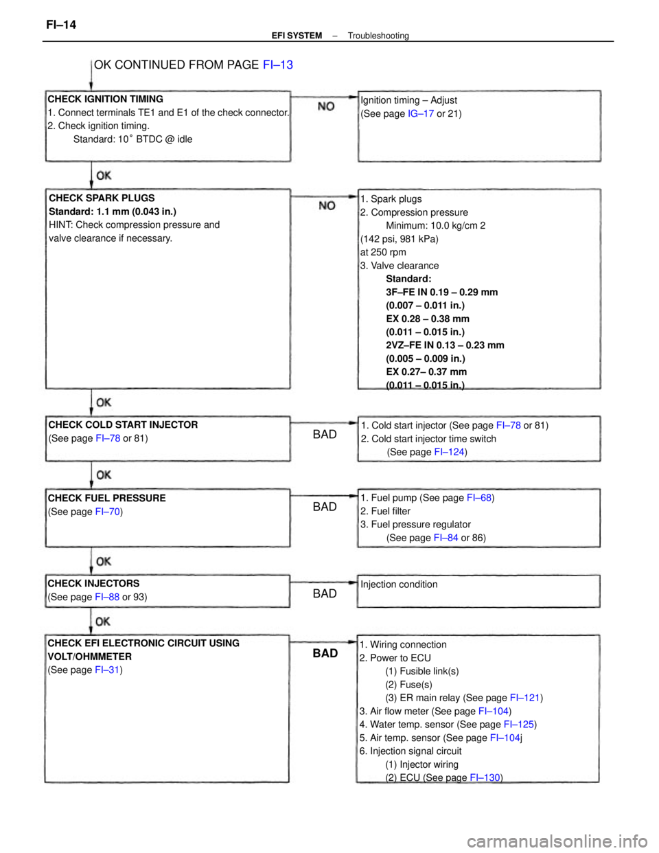
1. Spark plugs
2. Compression pressure
Minimum: 10.0 kg/cm 2
(142 psi, 981 kPa)
at 250 rpm
3. Valve clearance
Standard:
3F±FE IN 0.19 ± 0.29 mm
(0.007 ± 0.011 in.)
EX 0.28 ± 0.38 mm
(0.011 ± 0.015 in.)
2VZ±FE IN 0.13 ± 0.23 mm
(0.005 ± 0.009 in.)
EX 0.27± 0.37 mm
(0.011 ± 0.015 in.)
1. Wiring connection
2. Power to ECU
(1) Fusible link(s)
(2) Fuse(s)
(3) ER main relay (See page FI±121)
3. Air flow meter (See page FI±104)
4. Water temp. sensor (See page FI±125)
5. Air temp. sensor (See page FI±104j
6. Injection signal circuit
(1) Injector wiring
(2) ECU (See page FI±130) CHECK IGNITION TIMING
1. Connect terminals TE1 and E1 of the check connector.
2. Check ignition timing.
Standard: 10° BTDC @ idle
CHECK SPARK PLUGS
Standard: 1.1 mm (0.043 in.)
HINT: Check compression pressure and
valve clearance if necessary.
CHECK EFI ELECTRONIC CIRCUIT USING
VOLT/OHMMETER
(See page FI±31)1. Cold start injector (See page FI±78 or 81)
2. Cold start injector time switch
(See page FI±124)
1. Fuel pump (See page FI±68)
2. Fuel filter
3. Fuel pressure regulator
(See page FI±84 or 86) CHECK COLD START INJECTOR
(See page FI±78 or 81)
OK CONTINUED FROM PAGE FI±13
CHECK FUEL PRESSURE
(See page FI±70)Ignition timing ± Adjust
(See page IG±17 or 21)
CHECK INJECTORS
(See page FI±88 or 93)Injection condition
BADBAD
BAD BAD
± EFI SYSTEMTroubleshootingFI±14