Page 265 of 2389

A140E Automatic Transaxle (ECT)
WHAT IS THE ECT?
ECT means Electronic Controlled Transaxle. The hydraulic control system of the previous automatic
transaxle has been changed, the throttle and governor pressure have been replaced by electronic
signals and a micro computer has been used to give precise control of shift timing and lock±up tim-
ing.
FEATURES OF THE ECT
(a) The shift pattern can be chosen.
In the ECT ECU micro computer used in the A140E, two types of shift pattern, Power and Normal,
are recorded in the memory. By operating the pattern select switch, the driver can select the pre-
ferred shift pattern.
(b) Reduced fuel consumption and reduced shock during shifting is made possible.
Precise control of the shift timing by the ECT ECU, operation of the lock±up clutch from low speeds,
and decreased fuel consumption are made possible. Also, shock during Shifting is reduced.
(e) Self±Diagnostic System
When a malfunction occurs in the electronic control system, the driver is informed of this fact. Also,
there is a Self±Diagnostic System which displays the location of the malfunction when the service
connector is shorted.
(d) Fail±Safe System
A fail±Safe System is included so that, even if a malfunction occurs in the electronic control system,
the vehicle will be able to operate.
CONSTRUCTION AND OPERATION
When the A140E (ECT) is compared with the A140L, the automatic transaxle body has the same
construction and operation, with the exception of the hydraulic control system, as the A140L.
The electronic control system, which controls the shift timing and lock±up timing, has been added.
1. Hydraulic Control System (Comparison with the A140L)
VALVE BODY ± Additions or changes to solenoid valve
In the A140E there are three solenoid valves, the No. 1, the No. 2 and the lock±up solenoid valves.
Shifting occurs according to whether the No. 1 and No. 2 solenoid valves are ON or OFF, and the
lock±up solenoid valve controls the lock±up clutch.
GOVERNOR VALVE ± Removed
With the A140E, the governor valve has been replaced with a speed sensor, so that instead of the
governor pressure, a speed sensor signal is sent to the ECT ECU.
SHIFT CONTROL IN ECT
1. The vehicle speed is sensed by the vehicle speed
sensor, which sends this data to the
ECU in the form of electrical signals.
2. The angle to which the throttle is open is sensed
by the throttle position sensor, which sends this
data to the ECU in the form of electrical signals.
3. The ECT computer determines the shift point on
the basis of these two signals and operates the
solenoid valves in the hydraulic control unit, thus
shifting the transmission.
± AUTOMATIC TRANSAXLEDescription (A140L and A140E)AT±9
Page 1185 of 2389

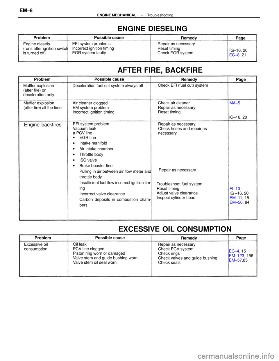
EFI system problem
Vacuum leak
a PCV line
wEGR tine
wIntake manifold
wAir intake chamber
wThrottle body
wISC valve
wBrake booster fine
Pulling in air between air flow meter and
throttle body
Insufficient fuel flow incorrect ignition tim-
ing
Incorrect valve clearance
Carbon deposits in combustion cham-
bers
Oil leak
PCV line clogged
Piston ring worn or damaged
Valve stem and guide bushing worn
Valve stem oil seal wornRepair as necessary
Check PCV system
Check rings
Check valves and guide bushing
Check seals Troubleshoot fuel system
Reset timing
Adjust valve clearance
Inspect cylinder headRepair as necessary
Check hoses and repair as
necessary Air cleaner clogged
EM system problem
Incorrect ignition timing EFI system problems
Incorrect ignition timing
EGR system faulty
Deceleration fuel cut system always off
Check air cleaner
Repair as necessary
Reset timing Repair as necessary
Reset timing
Check EGR system
EXCESSIVE OIL CONSUMPTION
Engine diesels
(runs after ignition switch
is turned off)
Muffler explosion
(after fire) on
deceleration only
FI±10
IG ±16, 20
EM±11, 15
EM±56, 84 Muffler explosion
(after fire) all the time
AFTER FIRE, BACKFIRE
EC±4, 15
EM±123, 156
EM±57,85
ENGINE DIESELING
Check EFI (fuel cut) system
Excessive oil
consumptionRepair as necessary
IG±16, 20
EC±8, 21
Engine backfires
Possible cause Possible cause
Possible causelG±16, 20 Problem
Problem
RemedyRemedy
ProblemRemedy
Page Page
MA±5Page
± ENGINE MECHANICALTroubleshootingEM±8
Page 1186 of 2389
Fuel leak
Air cleaner clogged
Incorrect ignition timing
EFI system problems
wInjector faulty
wDeceleration fuel cut system faulty
Idle speed too high
Spark plug faulty
EGR system always on
Low compression
Tires improperly inflated
Clutch slips
Brakes drag
Incorrect idle speed
Incorrect ignition timing
Vacuum leaks
wPCV line
wEGR line
wIntake manifold
wAir intake chamber
wThrottle body
wISC valve
wBrake booster line
EFI system problemsCheck ISC system
Inspect plugs
Check EGR system
Check compression
Inflate tires to proper pressure
Troubleshoot clutch
Troubleshoot brakesRepair as necessary
Check air cleaner
Reset timing
Repair as necessary
EXCESSIVE FUEL CONSUMPTION
Check ISC system
Reset timing
Repair as necessaryFI±116,118
IG±6, 10
EC±8, 21
EM±22
UNPLEASANT ODOR
Poor gasoline
mileage
FI±116, 118
IG±16, 20
Repair as necessaryMA±5
IG±16, 20
Unpleasant odorPossible cause Possible cause
Problem
ProblemRemedy
RemedyPage Page
± ENGINE MECHANICALTroubleshootingEM±9
Page 1199 of 2389

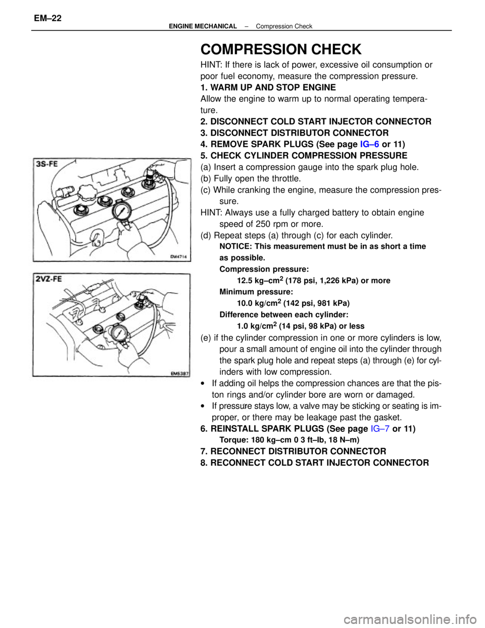
COMPRESSION CHECK
HINT: If there is lack of power, excessive oil consumption or
poor fuel economy, measure the compression pressure.
1. WARM UP AND STOP ENGINE
Allow the engine to warm up to normal operating tempera-
ture.
2. DISCONNECT COLD START INJECTOR CONNECTOR
3. DISCONNECT DISTRIBUTOR CONNECTOR
4. REMOVE SPARK PLUGS (See page IG±6 or 11)
5. CHECK CYLINDER COMPRESSION PRESSURE
(a) Insert a compression gauge into the spark plug hole.
(b) Fully open the throttle.
(c) While cranking the engine, measure the compression pres-
sure.
HINT: Always use a fully charged battery to obtain engine
speed of 250 rpm or more.
(d) Repeat steps (a) through (c) for each cylinder.
NOTICE: This measurement must be in as short a time
as possible.
Compression pressure:
12.5 kg±cm
2 (178 psi, 1,226 kPa) or more
Minimum pressure:
10.0 kg/cm
2 (142 psi, 981 kPa)
Difference between each cylinder:
1.0 kg/cm
2 (14 psi, 98 kPa) or less
(e) if the cylinder compression in one or more cylinders is low,
pour a small amount of engine oil into the cylinder through
the spark plug hole and repeat steps (a) through (e) for cyl-
inders with low compression.
wIf adding oil helps the compression chances are that the pis-
ton rings and/or cylinder bore are worn or damaged.
wIf pressure stays low, a valve may be sticking or seating is im-
proper, or there may be leakage past the gasket.
6. REINSTALL SPARK PLUGS (See page IG±7 or 11)
Torque: 180 kg±cm 0 3 ft±Ib, 18 N±m)
7. RECONNECT DISTRIBUTOR CONNECTOR
8. RECONNECT COLD START INJECTOR CONNECTOR
± ENGINE MECHANICALCompression CheckEM±22