Page 20 of 2389

ItemCapacity
Classification
Liters US qts
Imp. qts
Automatic
transaxle fluid
(w/o Differential
oil)A540E
Dry fill
Drain and refill5.9
2.56.2
2.65.2
2.2ATF DEXRON� II
A54H
Dry fill
Drain and refill7.0
3.37.4
3.56.2
2.9ATF type T (08886 - 00405) or equivalent
Differential oil
(w/ Automatic transaxle)
SV21 series
VZV21 series1.6
1.01.7
1.11.4
0.9ATF DEXRON� II
Transfer oil (A540H)
0.7
0.74 0.62
Recommended oil
Oil grade: API GL-5
Viscosity: SAE 75W-90 or 80W-90
SAE 90W
[above -18°C (0°F)]
SAE 80W
[below -18°C (0°F)]
Transaxle oil E50 (08885 - 80206) or
equivalent
Part tightenedkg-cm ft-lbN-m
Transfer right case y Oil strainer
Transfer left case y Rear wheel speed sensor
Transfer left case y Transfer inspection hole cover
Transfer left case y Drain plug
Transfer left case y Driven pinion bearing cage
Driven pinion bearing cage y Transfer extension housing
Transfer extension housing y Dynamic damper
Transfer right case y Oil pump cover
Transfer ring gear y Ring gear mounting case
Center differential control solenoid y Transfer valve body
Transfer valve body y Transfer left case
Neutral start switch bolt
Neutral start switch nut
Transfer assembly y Transaxle case48 in.-lb
48 in.-lb
12
29
29
19
19
69 in.-lb
71
10
8
48 in.-lb
61 in.-lb
51 55
55
160
400
400
260
260
80
985
145
11 0
55
70
7005.4
5.4
16
39
39
25
25
7.8
97
14
11
5.4
6.9
69
Torque Specifications (Cont'd)
LUBRICANT
- SERVICE SPECIFICATIONSAutomatic Transaxle Transfer (A540E A540H)A-9
Page 992 of 2389

(d) To release the air, loosen the union bolt of the water out-
let five revolutions.
(e) Slowly fill the system with coolant.
Use a good brand of ethylene±glycol base coolant,
mixed according to the manufacturer's directions.
Capacity (w/ Heater):
M/T 9.5 liters (10.0 US qts, 8.4 Imp. qts)
A/T 9.4 liters (9.9 US qts, 8.3 Imp. qts)
(f) Tighten the union bolt of the water outlet.
Torque: 180 kg±cm (13 ft±Ib, 18 N±m)
(g) Install the radiator cap.
(h) Start the engine and check for leaks.
(i) Recheck the coolant level and refill as necessary.
HINT: When the coolant has been depleted, refill with
coolant and repeat steps (d) to (i). 4. (2VZ±FE)
REPLACE ENGINE COOLANT
(a) Remove the radiator cap.
CAUTION: To avoid the danger of being burned, do not re-
move it while the engine and radiator are still hot as fluid
and steam can be blown out under pressure.
(b) Drain the coolant from the radiator and engine drain cocks.
(Engine drain cocks are at the front center and rear right
of the cylinder block.)
(c) Close the drain cocks.
Torque (Engine drain cock):
300 kg±cm (22 ft±Ib, 29 N±m)
NOTICE:
wDo not use alcohol type coolant.
wThe coolant should be mixed with demineralized
water or distilled water.
Capacity (w/ Heater).
M/T 6.4 liters (6.8 US qts, 5.6 Imp. qts)
A/T (2WD) 6.3 liters (6.7 US qts, 5.5 Imp. qts)
A/T (4WD) 6.8 liters (7.2 US qts, 6.0 Imp. qts)
(e) Install the radiator cap.
(f) Start the engine and check for leaks.
(g) Recheck the coolant level and refill as necessary. (d) Fill the system with coolant.
Use a good brand of ethylene±glycol base coolant, mixed
according to the manufacturer's directions.
Using coolant which includes more than 5O%
ethylene±glycol (but less than 70%) is recommended.
± COOLING SYSTEMCheck and Replacement of Engine CoolantCO±5
Page 996 of 2389
REMOVAL OF WATER PUMP
1. DRAIN ENGINE COOLANT (See page CO±5)
2. DISCONNECT RADIATOR LOWER NOSE FROM
WATER INLET PIPE
3. DISCONNECT TIMING BELT FROM WATER PUMP
PULLEY (See pages EM±34 to 39)
4. REMOVE WATER INLET PIPE
(a) Remove the bolt holding the water inlet pipe to the alternator
belt adjusting bar.
(b) Remove the water inlet pipe and 0±ring.
5. REMOVE WATER INLET AND THERMOSTAT
(See steps 4 and 5 on page CO±13)
WATER PUMP(2VZ±FE)
COMPONENTS
± COOLING SYSTEMWater Pump (2VZ±FE)CO±9
Page 1003 of 2389

REMOVAL OF RADIATO
1. DRAIN ENGINE COOLANT (See page CO±4 or 5)
2. REMOVE BATTERY
3. REMOVE IGNITION COIL (2VZ±FE), IGNITER AND
BRACKET ASSEMBLY
4. DISCONNECT COOLANT RESERVOIR HOSE
5. DISCONNECT RADIATOR NOSE
6. DISCONNECT COOLING FAN MOTOR
CONNECTOR(S)
7. (A/T)
DISCONNECT OIL COOLER HOSES
8. REMOVE RADIATOR AND ELECTRIC COOLING
FAN(S)
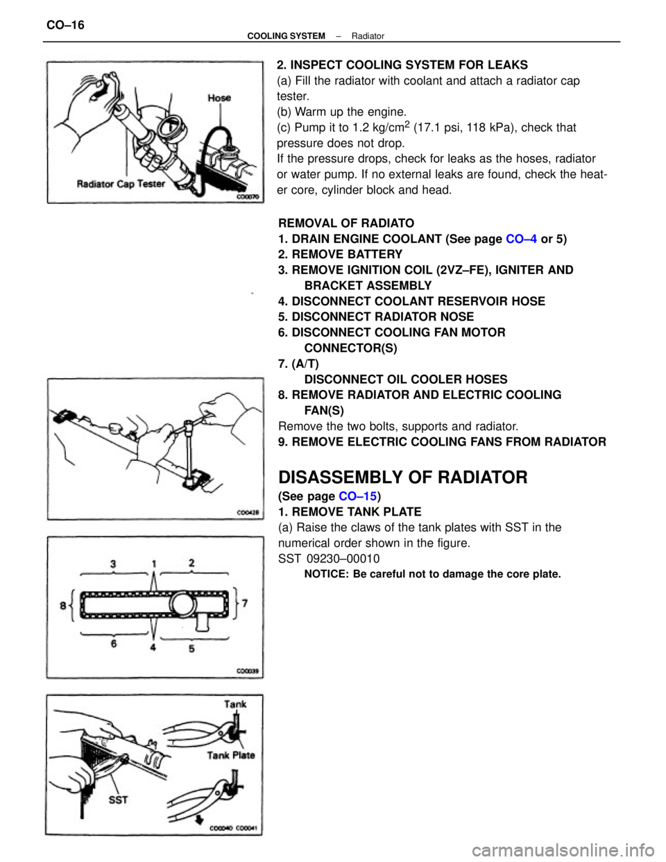
Remove the two bolts, supports and radiator.
9. REMOVE ELECTRIC COOLING FANS FROM RADIATOR
DISASSEMBLY OF RADIATOR
(See page CO±15)
1. REMOVE TANK PLATE
(a) Raise the claws of the tank plates with SST in the
numerical order shown in the figure.
SST 09230±00010
NOTICE: Be careful not to damage the core plate.
2. INSPECT COOLING SYSTEM FOR LEAKS
(a) Fill the radiator with coolant and attach a radiator cap
tester.
(b) Warm up the engine.
(c) Pump it to 1.2 kg/cm
2 (17.1 psi, 118 kPa), check that
pressure does not drop.
If the pressure drops, check for leaks as the hoses, radiator
or water pump. If no external leaks are found, check the heat-
er core, cylinder block and head.
± COOLING SYSTEMRadiatorCO±16
Page 1108 of 2389

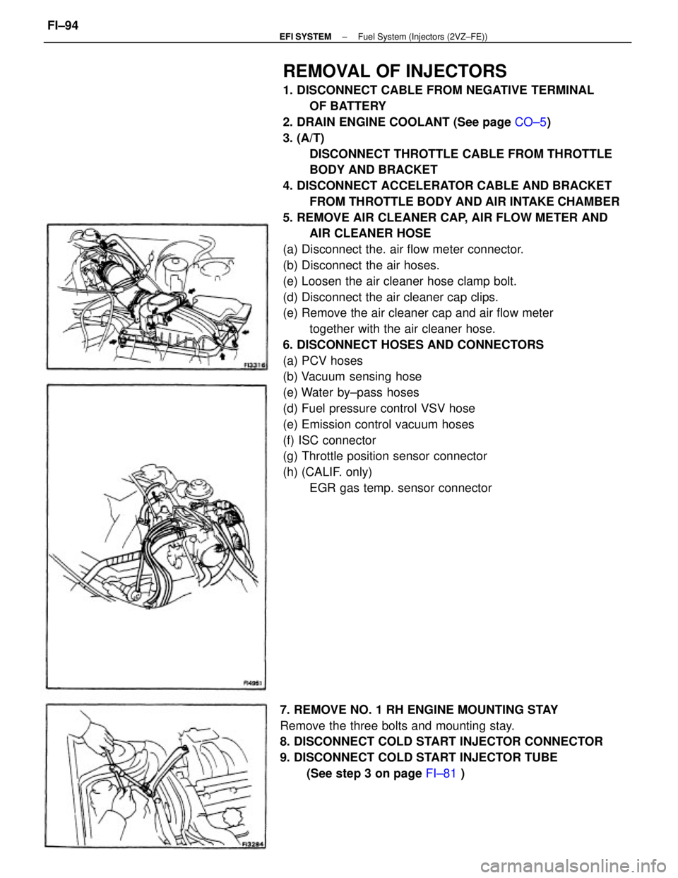
REMOVAL OF INJECTORS
1. DISCONNECT CABLE FROM NEGATIVE TERMINAL
OF BATTERY
2. DRAIN ENGINE COOLANT (See page CO±5)
3. (A/T)
DISCONNECT THROTTLE CABLE FROM THROTTLE
BODY AND BRACKET
4. DISCONNECT ACCELERATOR CABLE AND BRACKET
FROM THROTTLE BODY AND AIR INTAKE CHAMBER
5. REMOVE AIR CLEANER CAP, AIR FLOW METER AND
AIR CLEANER HOSE
(a) Disconnect the. air flow meter connector.
(b) Disconnect the air hoses.
(e) Loosen the air cleaner hose clamp bolt.
(d) Disconnect the air cleaner cap clips.
(e) Remove the air cleaner cap and air flow meter
together with the air cleaner hose.
6. DISCONNECT HOSES AND CONNECTORS
(a) PCV hoses
(b) Vacuum sensing hose
(e) Water by±pass hoses
(d) Fuel pressure control VSV hose
(e) Emission control vacuum hoses
(f) ISC connector
(g) Throttle position sensor connector
(h) (CALIF. only)
EGR gas temp. sensor connector
7. REMOVE NO. 1 RH ENGINE MOUNTING STAY
Remove the three bolts and mounting stay.
8. DISCONNECT COLD START INJECTOR CONNECTOR
9. DISCONNECT COLD START INJECTOR TUBE
(See step 3 on page FI±81 )
± EFI SYSTEMFuel System (Injectors (2VZ±FE))FI±94
Page 1121 of 2389

(d) Reconnect the sensor connector.
REMOVAL OF THROTTLE BODY
1. DRAIN ENGINE COOLANT (See page CO±4)
2. (A/T)
DISCONNECT THROTTLE CABLE FROM THROTTLE
LINKAGE
3. DISCONNECT ACCELERATOR CABLE FROM
THROTTLE LINKAGE
4. DISCONNECT AIR CLEANER HOSE
5. DISCONNECT THROTTLE POSITION SENSOR
CONNECTOR
6. DISCONNECT ISC VALVE CONNECTOR
7. REMOVE THROTTLE BODY
(a) Disconnect the following hoses:
wPCV hose
wWater by±pass hoses
wAir tube hose
wEmission control vacuum hoses
INSPECTION OF THROTTLE BODY
1. CLEAN THROTTLE BODY
(a) Using a soft brush and carburetor cleaner, clean the cast
parts.
(b) Using compressed air, clean all the passages and apertures.
NOTICE: To prevent deterioration, do not clean the throttle
position sensor.
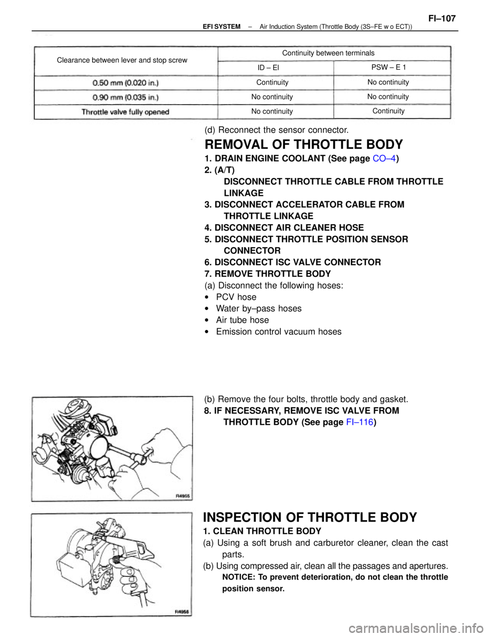
(b) Remove the four bolts, throttle body and gasket.
8. IF NECESSARY, REMOVE ISC VALVE FROM
THROTTLE BODY (See page FI±116)
Clearance between lever and stop screwContinuity between terminals
No continuity
No continuity
No continuity
No continuityPSW ± E 1
Continuity
Continuity ID ± El
± EFI SYSTEMAir Induction System (Throttle Body (3S±FE w o ECT))FI±107
Page 1127 of 2389
(d) Reconnect the sensor connector.
REMOVAL OF THROTTLE BODY
1. DRAIN ENGINE COOLANT (See page CO±5)
2. (A/T)
DISCONNECT THROTTLE CABLE FROM THROTTLE
LINKAGE
3. DISCONNECT ACCELERATOR CABLE FROM
THROTTLE LINKAGE
4. REMOVE AIR CLEANER CAP, AIR FLOW METER AND
AIR CLEANER HOSE
(a) Disconnect the air flow meter connector.
(b) Disconnect the air hoses.
(c) Loosen the air cleaner hose clamp bolt.
(d) Disconnect the air cleaner cap clips.
(e) Remove the air cleaner cap, air flow meter and air cleaner
hose assembly.
5. DISCONNECT THROTTLE POSITION SENSOR
CONNECTOR
6. REMOVE THROTTLE BODY
(a) Disconnect the following hoses:
wPCV hose
wWater by±pass hoses
wEmission control vacuum hoses
(b) (A/T)
Remove the two bolts and throttle cable bracket.
(c) Remove the four (M/T) or three (A/T) bolts, throttle body
and gasket.
Clearance between
lever and stop screwBetween
terminalsResistance
± EFI SYSTEMAir Induction System (Throttle Body (2VZ±FE))FI±113
Page 1226 of 2389

REMOVAL OF CYLINDER HEAD
(See page EM±48)
1. DISCONNECT CABLE FROM NEGATIVE TERMINAL
OF BATTERY
2. DRAIN ENGINE COOLANT (See page CO±4)
3. (A/T)
DISCONNECT THROTTLE CABLE AND BRACKET FROM
THROTTLE BODY
4. DISCONNECT ACCELERATOR CABLE AND BRACKET
FROM THROTTLE BODY AND AIR INTAKE CHAMBER
5. REMOVE CRUISE CONTROL ACTUATOR
(See step 9 on page EM±108)
6. REMOVE AIR CLEANER HOSE
7. REMOVE ALTERNATOR (See page CH±6)
8. REMOVE OIL PRESSURE SWITCH, ENGINE HANGERS
AND ALTERNATOR UPPER BRACKET
9. RAISE VEHICLE
NOTICE: Be sure the vehicle is securely supported.
10. REMOVE RH FRONT WHEEL
11. REMOVE ENGINE RH UNDER COVER
12. REMOVE SUSPENSION LOWER CROSSMEMBER
(See step 20 on page EM±109)
13. DISCONNECT FRONT EXHAUST PIPE FROM
CATALYTIC CONVERTER
(See step 25 on page EM±110)
14. REMOVE EXHAUST MANIFOLD AND CATALYTIC
CONVERTER ASSEMBLY
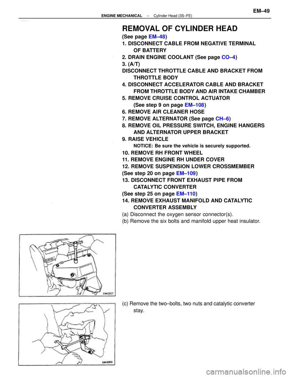
(a) Disconnect the oxygen sensor connector(s).
(b) Remove the six bolts and manifold upper heat insulator.
(c) Remove the two±bolts, two nuts and catalytic converter
stay.
± ENGINE MECHANICALCylinder Head (3S±FE)EM±49