Page 816 of 2389

HINT:
wRefer to 0/M for operation details of ANTI±THEFT SYSTEM.
wWhen the ID number has been cancelled, reset the same number after completing the operation, or in-
form the customer that it has been cancelled.ANTI±THEFT SYSTEM
operating condition.
(ID number input error 5
times) Take to designated
radio service station. While holding the 1, 4 and6
buttons in. Push and hold the
ºPVIIR VOLº knob. Check
display.
ANTI±THEFT SYSTEM
operating condition.
(ID number input error 4
times or less)
ANTI±THEFT SYSTEM not cancelled. ID number input 5 times or more?
Troubleshooting for ANTI±THEFT SYSTEM
Turn ignition key from LOCK position to ACC position.
ANTI±THEFT SYSTEM cancelled.
Check audio system again.
(Liquid Crystal Display (LCD) for Audio System)Cancel ID number, refer to each malfunction item.Cancel ID number, refer to each malfunction
item. Normal operation when radio
switch turned ON?
Take to designated radio service station.Refer to each malfunction
item.
ºSECº display disappears
after 1 second.ID number not input.
(Display D)
ID number not
input, or else
input error. After 2 seconds
Display C ± A Input ID number, check display.Forgot to press switch. Radio switch turned 4N. Display A showing?
Display B showing? ID nubmer is set.
Display A or BDisplay
EDisplay
B
Display DYe s
Ye sYe s Ye s
Ye s
± BODY ELECTRICAL SYSTEMAudio SystemBE±94
Page 1230 of 2389

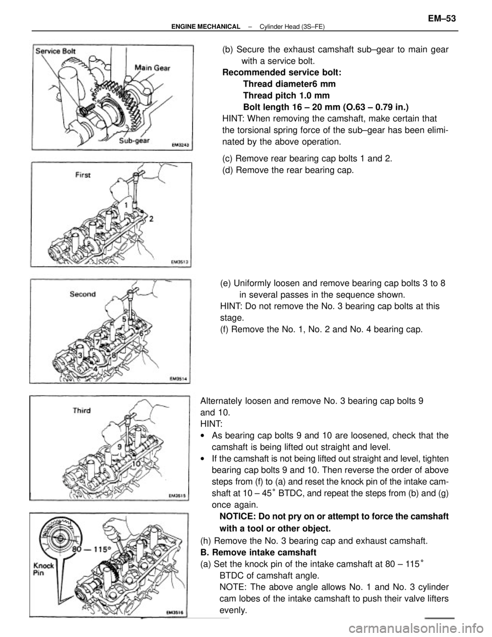
Alternately loosen and remove No. 3 bearing cap bolts 9
and 10.
HINT:
wAs bearing cap bolts 9 and 10 are loosened, check that the
camshaft is being lifted out straight and level.
wIf the camshaft is not being lifted out straight and level, tighten
bearing cap bolts 9 and 10. Then reverse the order of above
steps from (f) to (a) and reset the knock pin of the intake cam-
shaft at 10 ± 45° BTDC, and repeat the steps from (b) and (g)
once again.
NOTICE: Do not pry on or attempt to force the camshaft
with a tool or other object.
(h) Remove the No. 3 bearing cap and exhaust camshaft.
B. Remove intake camshaft
(a) Set the knock pin of the intake camshaft at 80 ± 115°
BTDC of camshaft angle.
NOTE: The above angle allows No. 1 and No. 3 cylinder
cam lobes of the intake camshaft to push their valve lifters
evenly.(b) Secure the exhaust camshaft sub±gear to main gear
with a service bolt.
Recommended service bolt:
Thread diameter6 mm
Thread pitch 1.0 mm
Bolt length 16 ± 20 mm (O.63 ± 0.79 in.)
HINT: When removing the camshaft, make certain that
the torsional spring force of the sub±gear has been elimi-
nated by the above operation.
(e) Uniformly loosen and remove bearing cap bolts 3 to 8
in several passes in the sequence shown.
HINT: Do not remove the No. 3 bearing cap bolts at this
stage.
(f) Remove the No. 1, No. 2 and No. 4 bearing cap.(c) Remove rear bearing cap bolts 1 and 2.
(d) Remove the rear bearing cap.
± ENGINE MECHANICALCylinder Head (3S±FE)EM±53
Page 1231 of 2389

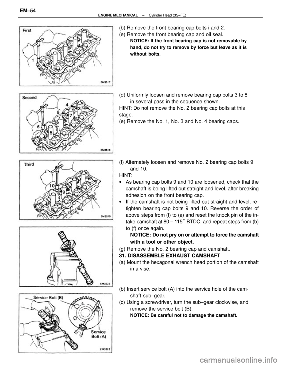
(f) Alternately loosen and remove No. 2 bearing cap bolts 9
and 10.
HINT:
wAs bearing cap bolts 9 and 10 are loosened, check that the
camshaft is being lifted out straight and level, after breaking
adhesion on the front bearing cap.
wIf the camshaft is not being lifted out straight and level, re-
tighten bearing cap bolts 9 and 10. Reverse the order of
above steps from (f) to (a) and reset the knock pin of the in-
take camshaft at 80 ± 115° BTDC, and repeat steps from (b)
to (f) once again.
NOTICE: Do not pry on or attempt to force the camshaft
with a tool or other object.
(g) Remove the No. 2 bearing cap and camshaft.
31. DISASSEMBLE EXHAUST CAMSHAFT
(a) Mount the hexagonal wrench head portion of the camshaft
in a vise.
(b) Insert service bolt (A) into the service hole of the cam-
shaft sub±gear.
(c) Using a screwdriver, turn the sub±gear clockwise, and
remove the service bolt (B).
NOTICE: Be careful not to damage the camshaft.
(d) Uniformly loosen and remove bearing cap bolts 3 to 8
in several pass in the sequence shown.
HINT: Do not remove the No. 2 bearing cap bolts at this
stage.
(e) Remove the No. 1, No. 3 and No. 4 bearing caps. (b) Remove the front bearing cap bolts i and 2.
(e) Remove the front bearing cap and oil seal.
NOTICE: If the front bearing cap is not removable by
hand, do not try to remove by force but leave as it is
without bolts.
± ENGINE MECHANICALCylinder Head (3S±FE)EM±54