Page 963 of 2389
1. INSPECT RELAY CONTINUITY
(a) Using an ohmmeter, check that there is continuity between
terminals 1 and 3.
(b) Check that there is continuity between terminals 2 and
4.
(c) Check that there is no continuity between terminals 4
and 5.
If continuity is not as specified, replace the relay.
2. INSPECT RELAY OPERATION
(a) Apply battery voltage across terminals 1 and 3.
(b) Using an ohmmeter, check that there is continuity between
terminals 4 and 5.
(e) Check that there is no continuity between terminals 2
and 4.
If operation is not as specified, replace the relay.
ENGINE MAIN RELAY
INSPECTION OF ENGINE MAIN RELAY
LOCATION:
3S±FE In the relay box in the engine compartment.
2VZ±FE On the LH fender apron rear side in the engine
compartment.
± CHARGING SYSTEMEngine Main RelayCH±16
Page 1009 of 2389

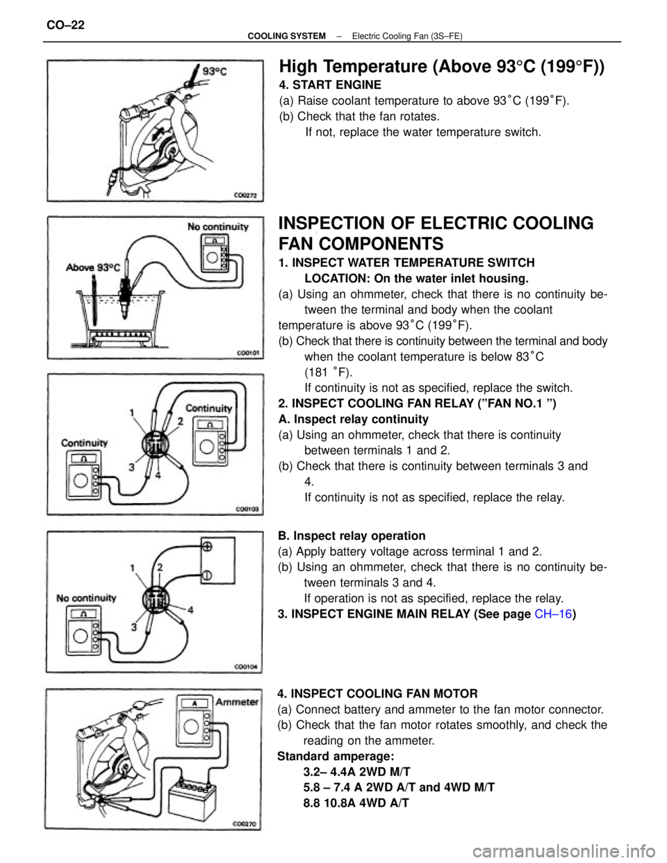
INSPECTION OF ELECTRIC COOLING
FAN COMPONENTS
1. INSPECT WATER TEMPERATURE SWITCH
LOCATION: On the water inlet housing.
(a) Using an ohmmeter, check that there is no continuity be-
tween the terminal and body when the coolant
temperature is above 93°C (199°F).
(b) Check that there is continuity between the terminal and body
when the coolant temperature is below 83°C
(181 °F).
If continuity is not as specified, replace the switch.
2. INSPECT COOLING FAN RELAY (ºFAN NO.1 º)
A. Inspect relay continuity
(a) Using an ohmmeter, check that there is continuity
between terminals 1 and 2.
(b) Check that there is continuity between terminals 3 and
4.
If continuity is not as specified, replace the relay.
4. INSPECT COOLING FAN MOTOR
(a) Connect battery and ammeter to the fan motor connector.
(b) Check that the fan motor rotates smoothly, and check the
reading on the ammeter.
Standard amperage:
3.2± 4.4A 2WD M/T
5.8 ± 7.4 A 2WD A/T and 4WD M/T
8.8 10.8A 4WD A/T B. Inspect relay operation
(a) Apply battery voltage across terminal 1 and 2.
(b) Using an ohmmeter, check that there is no continuity be-
tween terminals 3 and 4.
If operation is not as specified, replace the relay.
3. INSPECT ENGINE MAIN RELAY (See page CH±16)
High Temperature (Above 935C (1995F))
4. START ENGINE
(a) Raise coolant temperature to above 93°C (199°F).
(b) Check that the fan rotates.
If not, replace the water temperature switch.
± COOLING SYSTEMElectric Cooling Fan (3S±FE)CO±22
Page 2324 of 2389
1. INSPECT RELAY CONTINUITY
(a) Using an ohmmeter, check that there is continuity between
terminals 1 and 3.
(b) Check that there is no continuity between terminals 2
and 4.
If continuity is not as specified, replace the relay.
2. INSPECT RELAY OPERATION
(a) Apply battery voltage across terminals 1 and 3.
(b) Using an ohmmeter, check that there is continuity between
terminals 2 and 4.
If operation is not as specified, replace the relay.
STARTER RELAY (MT only)
INSPECTION OF STARTER RELAY
LOCATION: In the left cowl side.
CLUTCH START SWITCH (MT only)
(See page CL±4)
± STARTING SYSTEMStarter Relay (M T only)ST±16
Page 2325 of 2389
1. INSPECT RELAY CONTINUITY
(a) Using an ohmmeter, check that there is continuity between
terminals 1 and 3.
(b) Check that there is no continuity between terminals 2
and 4.
If continuity is not as specified, replace the relay.
2. INSPECT RELAY OPERATION
(a) Apply battery voltage across terminals 1 and 3.
(b) Using an ohmmeter, check that there is continuity between
terminals 2 and 4.
If operation is not as specified, replace the relay.
STARTER RELAY (MT only)
INSPECTION OF STARTER RELAY
LOCATION: In the left cowl side.
CLUTCH START SWITCH (MT only)
(See page CL±4)
± STARTING SYSTEMClutch Start Switch (M T only)ST±16