Page 1237 of 2389

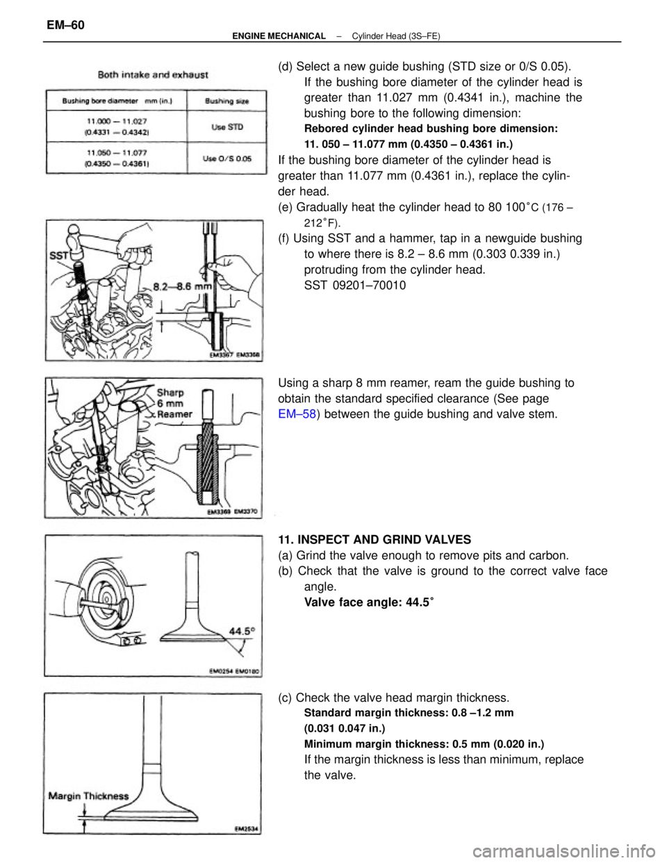
(d) Select a new guide bushing (STD size or 0/S 0.05).
If the bushing bore diameter of the cylinder head is
greater than 11.027 mm (0.4341 in.), machine the
bushing bore to the following dimension:
Rebored cylinder head bushing bore dimension:
11. 050 ± 11.077 mm (0.4350 ± 0.4361 in.)
If the bushing bore diameter of the cylinder head is
greater than 11.077 mm (0.4361 in.), replace the cylin-
der head.
(e) Gradually heat the cylinder head to 80 100
°C (176 ±
212°F).
(f) Using SST and a hammer, tap in a newguide bushing
to where there is 8.2 ± 8.6 mm (0.303 0.339 in.)
protruding from the cylinder head.
SST 09201±70010
(c) Check the valve head margin thickness.
Standard margin thickness: 0.8 ±1.2 mm
(0.031 0.047 in.)
Minimum margin thickness: 0.5 mm (0.020 in.)
If the margin thickness is less than minimum, replace
the valve. 11. INSPECT AND GRIND VALVES
(a) Grind the valve enough to remove pits and carbon.
(b) Check that the valve is ground to the correct valve face
angle.
Valve face angle: 44.5
°
Using a sharp 8 mm reamer, ream the guide bushing to
obtain the standard specified clearance (See page
EM±58) between the guide bushing and valve stem.
± ENGINE MECHANICALCylinder Head (3S±FE)EM±60
Page 1265 of 2389

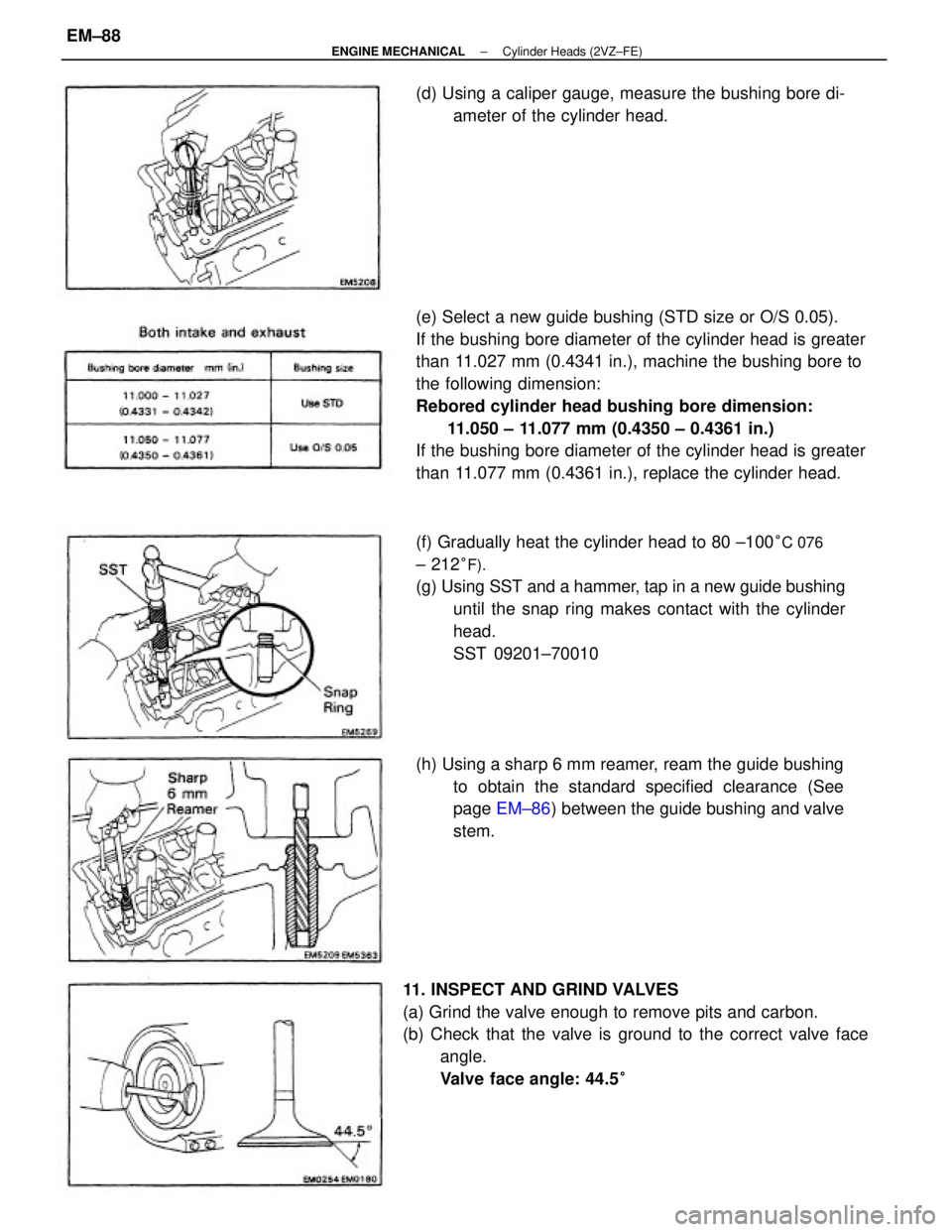
(e) Select a new guide bushing (STD size or O/S 0.05).
If the bushing bore diameter of the cylinder head is greater
than 11.027 mm (0.4341 in.), machine the bushing bore to
the following dimension:
Rebored cylinder head bushing bore dimension:
11.050 ± 11.077 mm (0.4350 ± 0.4361 in.)
If the bushing bore diameter of the cylinder head is greater
than 11.077 mm (0.4361 in.), replace the cylinder head.
11. INSPECT AND GRIND VALVES
(a) Grind the valve enough to remove pits and carbon.
(b) Check that the valve is ground to the correct valve face
angle.
Valve face angle: 44.5
°
(f) Gradually heat the cylinder head to 80 ±100°C 076
± 212°F).
(g) Using SST and a hammer, tap in a new guide bushing
until the snap ring makes contact with the cylinder
head.
SST 09201±70010
(h) Using a sharp 6 mm reamer, ream the guide bushing
to obtain the standard specified clearance (See
page EM±86) between the guide bushing and valve
stem. (d) Using a caliper gauge, measure the bushing bore di-
ameter of the cylinder head.
± ENGINE MECHANICALCylinder Heads (2VZ±FE)EM±88
Page 1360 of 2389

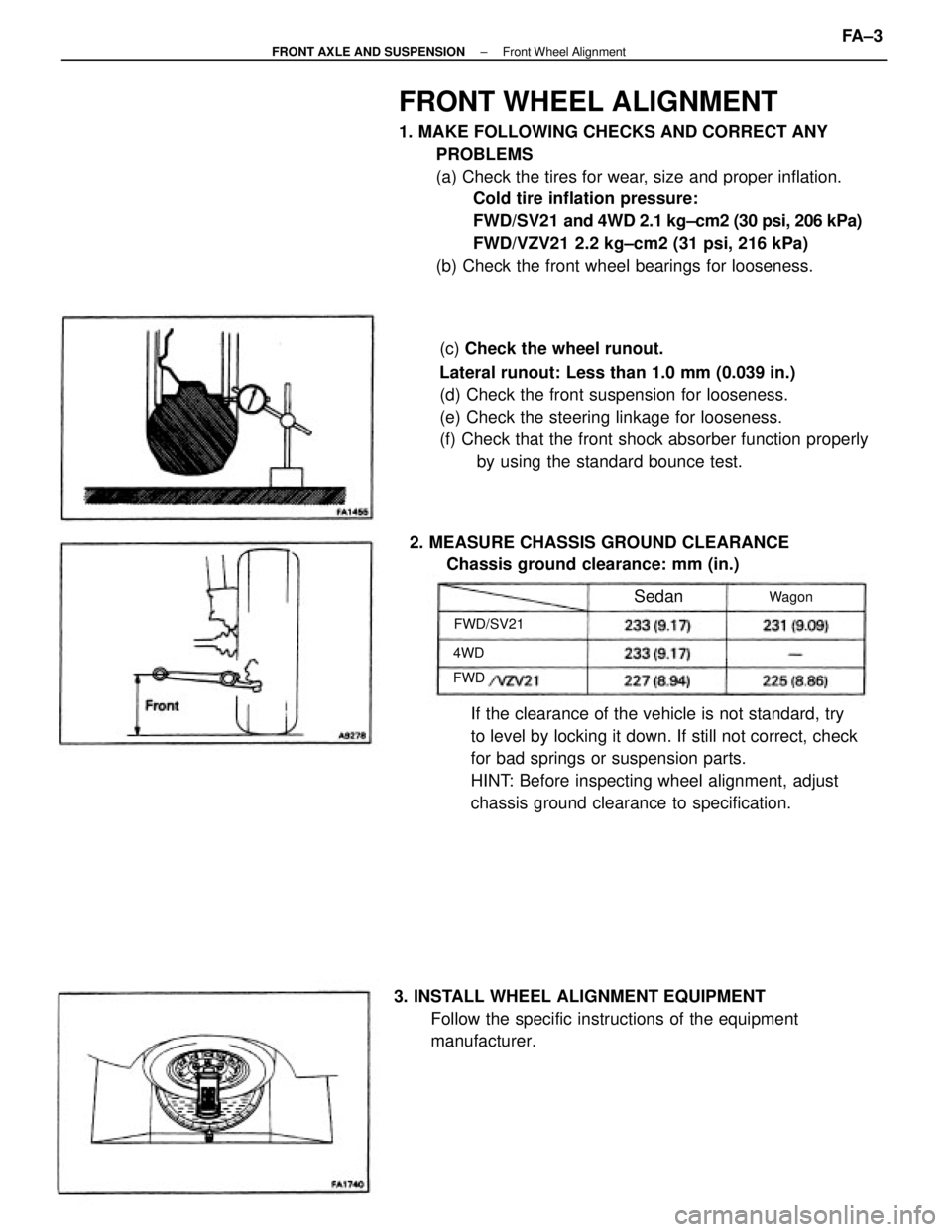
FRONT WHEEL ALIGNMENT
1. MAKE FOLLOWING CHECKS AND CORRECT ANY
PROBLEMS
(a) Check the tires for wear, size and proper inflation.
Cold tire inflation pressure:
FWD/SV21 and 4WD 2.1 kg±cm2 (30 psi, 206 kPa)
FWD/VZV21 2.2 kg±cm2 (31 psi, 216 kPa)
(b) Check the front wheel bearings for looseness.
(c) Check the wheel runout.
Lateral runout: Less than 1.0 mm (0.039 in.)
(d) Check the front suspension for looseness.
(e) Check the steering linkage for looseness.
(f) Check that the front shock absorber function properly
by using the standard bounce test.
If the clearance of the vehicle is not standard, try
to level by locking it down. If still not correct, check
for bad springs or suspension parts.
HINT: Before inspecting wheel alignment, adjust
chassis ground clearance to specification.
3. INSTALL WHEEL ALIGNMENT EQUIPMENT
Follow the specific instructions of the equipment
manufacturer. 2. MEASURE CHASSIS GROUND CLEARANCE
Chassis ground clearance: mm (in.)
FWD/SV21Wagon
Sedan
4WD
FWD
± FRONT AXLE AND SUSPENSIONFront Wheel AlignmentFA ± 3
Page 2149 of 2389
REAR WHEEL ALIGNMENT
1. MAKE FOLLOWING CHECKS AND CORRECT ANY
PROBLEMS
(a) Check the tires for wear, size and proper inflation
pressure.
Cold tire inflation pressure:
FWD/SV21 and 4WD 2.1 kg/cm2 (30 psi, 206 kPa)
FWD/VZV21 1.9 kg/cm2 (27 psi, 186 kPa)
(b) Check the front wheel bearings for looseness.
(e) Check the wheel runout.
Lateral runout: Less than 1.0 mm (0.039 in.)
(d) Check the front suspension for looseness.
(e) Check that the front shock absorber function properly
by using the standard bounce test.
If the clearance of the vehicle is not standard try to
level by locking it down. If still not correct, check
for bad springs or suspension parts.
HINT: Before inspecting wheel alignment, adjust
chassis ground clearance to specification. 2. MEASURE CHASSIS GROUND CLEARANCE
Chassis ground clearance: m m (in.)
3. INSPECT CAMBER
Camber: Inspection standard
Left±right error
30'
(Sedan)
(Wagon)Wagon Sedan
± REAR AXLE AND SUSPENSIONRear Wheel AlignmentRA±3
Page 2271 of 2389
Limit Lateral runout
Radial runout
Ring gear installing temperature
Drive pinion oil seal drive in depth
Side gear oil seal drive in depth
Side gear thrust washer thicknessDrive pinion bearing preload at Starting
New bearing
Reused bearing
Drive pinion to ring gear backlash
Pinion gear to side gear backlash
Ring gear runout
Companion flange runout
REAR AXLE AND SUSPENSION
Specifications
Camber (FWD /Sedan)
(FWD/Wagon)
(4WD)
Left±right error
Wheel lateral runout
Hub bearing axial direction(FWD/SV21 and 4WD)
(FWD/VZV21)
(FWD SV21)
(4WD)
(FIND/¿¿V21)
(FWD/SV21)
(FWD/VZV21)
(4WD)
Rear axle
and suspensionChassis ground
clearanceCold tire
inflation
pressure
Rear wheel
alignmentAdjustment STD Inspection STD
Total preloacf at Starting DifferentialWagon
Toe±inSedan
± SERVICE SPECIFICATIONSRear Axle and SuspensionA±33