Page 992 of 2389

(d) To release the air, loosen the union bolt of the water out-
let five revolutions.
(e) Slowly fill the system with coolant.
Use a good brand of ethylene±glycol base coolant,
mixed according to the manufacturer's directions.
Capacity (w/ Heater):
M/T 9.5 liters (10.0 US qts, 8.4 Imp. qts)
A/T 9.4 liters (9.9 US qts, 8.3 Imp. qts)
(f) Tighten the union bolt of the water outlet.
Torque: 180 kg±cm (13 ft±Ib, 18 N±m)
(g) Install the radiator cap.
(h) Start the engine and check for leaks.
(i) Recheck the coolant level and refill as necessary.
HINT: When the coolant has been depleted, refill with
coolant and repeat steps (d) to (i). 4. (2VZ±FE)
REPLACE ENGINE COOLANT
(a) Remove the radiator cap.
CAUTION: To avoid the danger of being burned, do not re-
move it while the engine and radiator are still hot as fluid
and steam can be blown out under pressure.
(b) Drain the coolant from the radiator and engine drain cocks.
(Engine drain cocks are at the front center and rear right
of the cylinder block.)
(c) Close the drain cocks.
Torque (Engine drain cock):
300 kg±cm (22 ft±Ib, 29 N±m)
NOTICE:
wDo not use alcohol type coolant.
wThe coolant should be mixed with demineralized
water or distilled water.
Capacity (w/ Heater).
M/T 6.4 liters (6.8 US qts, 5.6 Imp. qts)
A/T (2WD) 6.3 liters (6.7 US qts, 5.5 Imp. qts)
A/T (4WD) 6.8 liters (7.2 US qts, 6.0 Imp. qts)
(e) Install the radiator cap.
(f) Start the engine and check for leaks.
(g) Recheck the coolant level and refill as necessary. (d) Fill the system with coolant.
Use a good brand of ethylene±glycol base coolant, mixed
according to the manufacturer's directions.
Using coolant which includes more than 5O%
ethylene±glycol (but less than 70%) is recommended.
± COOLING SYSTEMCheck and Replacement of Engine CoolantCO±5
Page 1251 of 2389
26. INSTALL OIL PRESSURE SWITCH, ENGINE HANGERS
AND ALTERNATOR BRACKET
Torque the bolts.
Torque: 500 kg±cm (37 ft±Ib, 48 N±m)
27. INSTALL ALTERNATOR (See page CH±14)
28. INSTALL AIR CLEANER HOSE
29. INSTALL CRUISE CONTROL ACTUATOR
(See step 26 on page EM±137)
30. INSTALL RADIATOR RESERVOIR TANK
31. INSTALL ACCELERATOR CABLE, AND ADJUST IT
32. (A/T)
CONNECT THROTTLE CABLE, AND ADJUST IT
33. FILL WITH ENGINE COOLANT (See page CO±5)
Capacity (w/ Heater):
M/T 6.4 liters (6.8 US qts, 5.6 Imp. qts)
A/T (2WD) 6.3 liters (6.7 US qts, 5.5 Imp. qts)
A/T (4WD) 6.8 liters (7.2 US qts, 6.0 Imp. qts)
34. CONNECT CABLE TO NEGATIVE TERMINAL OF
BATTERY
35. START ENGINE AND CHECK FOR LEAKS
36. PERFORM ENGINE ADJUSTMENT
(a) Adjust the valve clearance. (See page EM±11)
Valve clearance (Cold):
Intake 0.19 ± 0.29 mm (0.007 ± 0.011 in.)
Exhaust 0.28 ± 0.38 mm (0.011 ± 0.015 in.)
(b) Adjust the ignition timing.
(See steps 7 to 10 on pages IG±16 and 17)
Ignition timing:
10° BTDC @ idle
(w/ Terminals TE 1 and E 1 connected)
37. CHECK TOE±IN (See page FA±5)
38. PERFORM ROAD TEST
Check for abnormal noise, shock, slippage, correct shift
points and smooth operation.
39. RECHECK ENGINE COOLANT LEVEL AND OIL LEVEL
± ENGINE MECHANICALCylinder Head (3S±FE)EM±74
Page 1283 of 2389
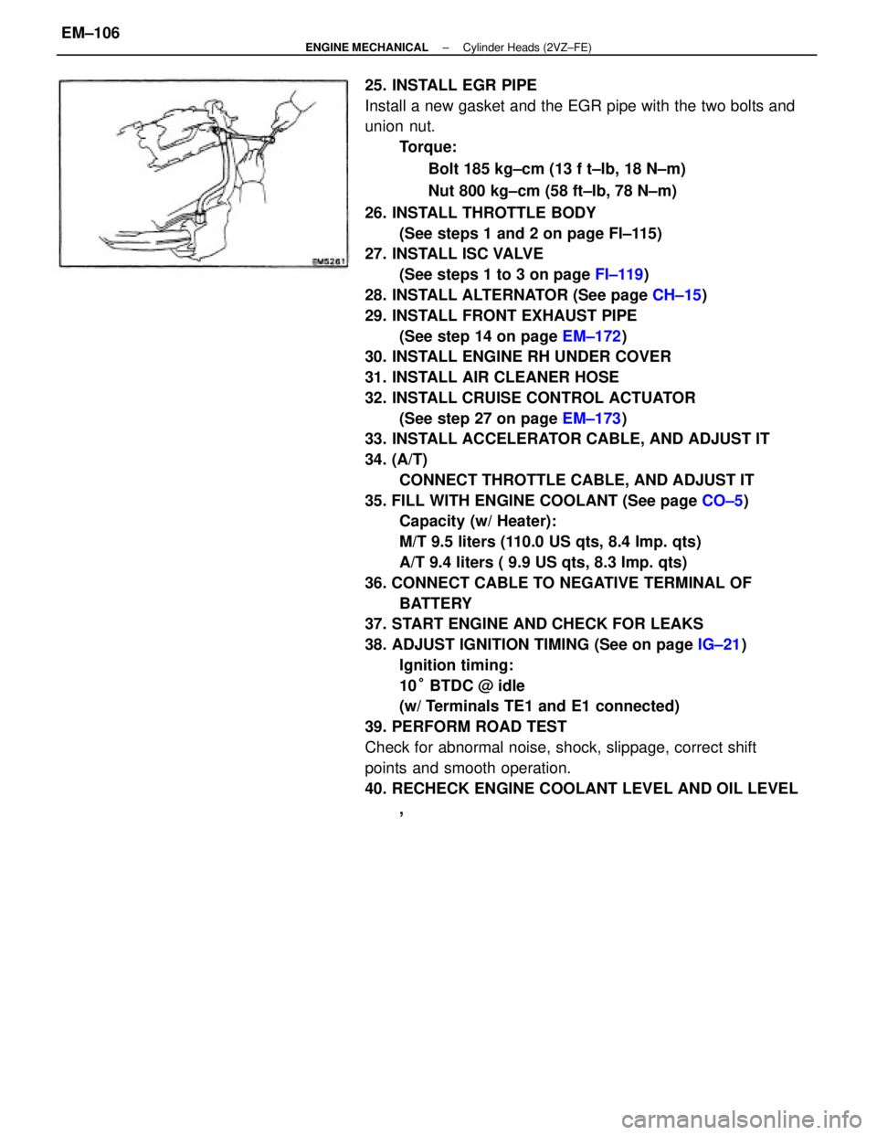
25. INSTALL EGR PIPE
Install a new gasket and the EGR pipe with the two bolts and
union nut.
Torque:
Bolt 185 kg±cm (13 f t±lb, 18 N±m)
Nut 800 kg±cm (58 ft±Ib, 78 N±m)
26. INSTALL THROTTLE BODY
(See steps 1 and 2 on page Fl±115)
27. INSTALL ISC VALVE
(See steps 1 to 3 on page FI±119)
28. INSTALL ALTERNATOR (See page CH±15)
29. INSTALL FRONT EXHAUST PIPE
(See step 14 on page EM±172)
30. INSTALL ENGINE RH UNDER COVER
31. INSTALL AIR CLEANER HOSE
32. INSTALL CRUISE CONTROL ACTUATOR
(See step 27 on page EM±173)
33. INSTALL ACCELERATOR CABLE, AND ADJUST IT
34. (A/T)
CONNECT THROTTLE CABLE, AND ADJUST IT
35. FILL WITH ENGINE COOLANT (See page CO±5)
Capacity (w/ Heater):
M/T 9.5 liters (110.0 US qts, 8.4 Imp. qts)
A/T 9.4 liters ( 9.9 US qts, 8.3 Imp. qts)
36. CONNECT CABLE TO NEGATIVE TERMINAL OF
BATTERY
37. START ENGINE AND CHECK FOR LEAKS
38. ADJUST IGNITION TIMING (See on page IG±21)
Ignition timing:
10° BTDC @ idle
(w/ Terminals TE1 and E1 connected)
39. PERFORM ROAD TEST
Check for abnormal noise, shock, slippage, correct shift
points and smooth operation.
40. RECHECK ENGINE COOLANT LEVEL AND OIL LEVEL
,
± ENGINE MECHANICALCylinder Heads (2VZ±FE)EM±106
Page 1315 of 2389
32. INSTALL BATTERY
33. FILL WITH ENGINE COOLANT (See page CO±5)
Capacity (w/ Heater):
M/T 6.4 liters (6.8 US qts, 5.6 Imp. qts)
A/T (2WD) 6.3 liters (6.7 US qts, 5.5 Imp. qts)
A/T (4WD) 6.8 liters (7.2 US qts, 6.0 Imp. qts)
34. FILL WITH ENGINE OIL (See page LU±8)
Capacity:
Drain and refill
w/ Oil filter change
3.9 liters (4.1 US qts, 3.4 Imp. qts)
w/o Oil filter change
3.7 liters (3.9 US qts, 3.3 Imp. qts)
Dry fill 4.3 liters (4.5 US qts, 3.8 Imp. qts)
35. START ENGINE AND CHECK FOR LEAKS
36. PERFORM ENGINE ADJUSTMENT
(a) Adjust the alternator drive belt.
(See page CH±3)
Drive belt tension:
w/ A/C New belt 175 + 5 lb
Used belt 130 + 10 lb
w/o A/C New belt 125 + 25 lb
Used belt 95 + 20 lb
(b) Adjust the PS drive belt.
Drive belt tension: New belt 125 + 25 lb
Used belt 80 + 20 lb
(c) Adjust the ignition timing.
(See steps 7 to 10 on pages IG±16 and 17)
Ignition timing:
10° BTDC @ idle
(w/ Terminals TE 1 and E1 connected)
(d) Adjust the valve. clearance. (See page EM±11)
Valve clearance:
Intake 0.19 ± 0.29 mm (0.007 ± 0.011 in.)
Exhaust 0.28 ± 0.38 mm (0.011 ± 0.015 in.)
37. INSTALL HOOD
38. PERFORM ROAD TEST
Check for abnormal noise, shock, slippage, correct shift
points and smooth operation.
39. RECHECK ENGINE COOLANT AND ENGINE OIL
LEVELS
± ENGINE MECHANICALCylinder Block (3S±FE)EM±138
Page 1351 of 2389
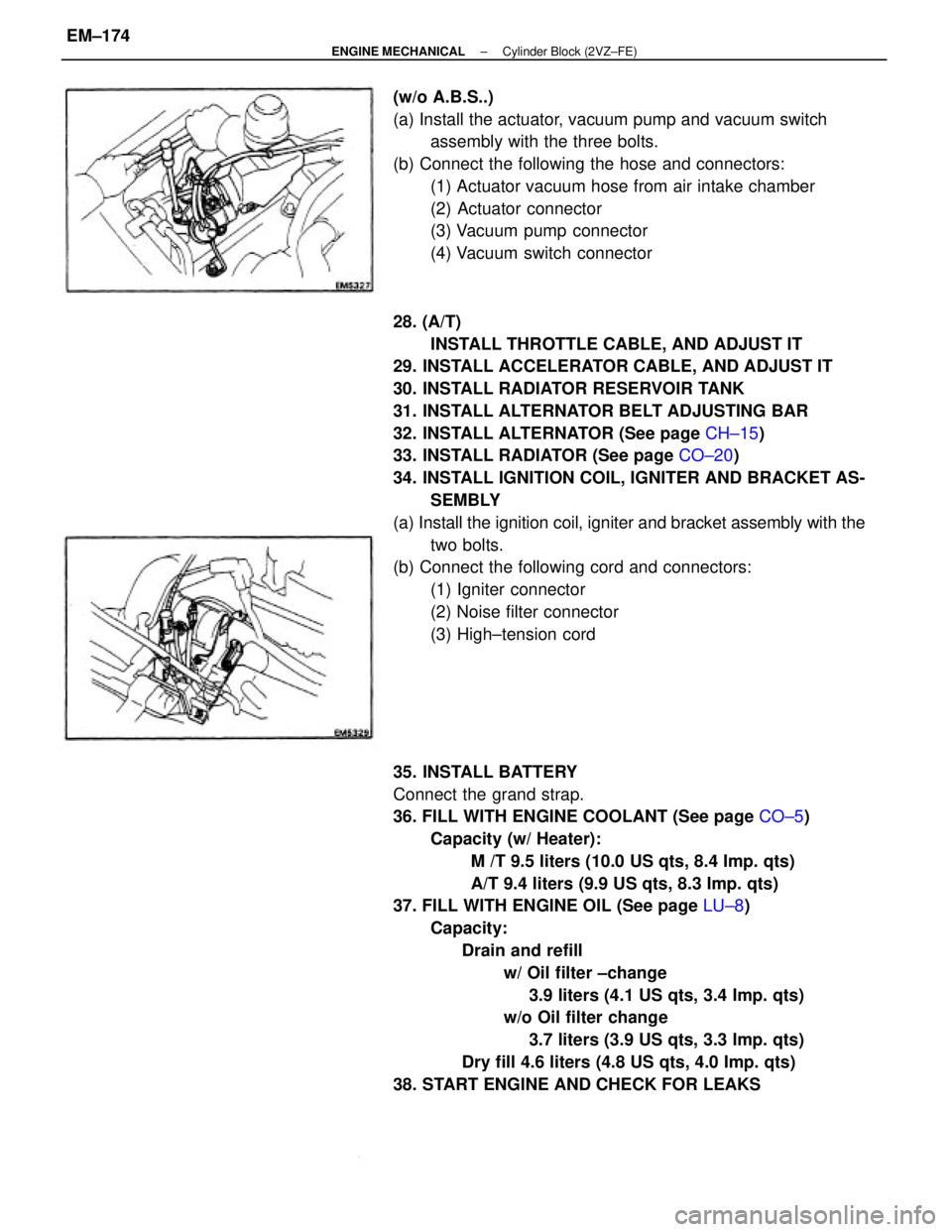
28. (A/T)
INSTALL THROTTLE CABLE, AND ADJUST IT
29. INSTALL ACCELERATOR CABLE, AND ADJUST IT
30. INSTALL RADIATOR RESERVOIR TANK
31. INSTALL ALTERNATOR BELT ADJUSTING BAR
32. INSTALL ALTERNATOR (See page CH±15)
33. INSTALL RADIATOR (See page CO±20)
34. INSTALL IGNITION COIL, IGNITER AND BRACKET AS-
SEMBLY
(a) Install the ignition coil, igniter and bracket assembly with the
two bolts.
(b) Connect the following cord and connectors:
(1) Igniter connector
(2) Noise filter connector
(3) High±tension cord
35. INSTALL BATTERY
Connect the grand strap.
36. FILL WITH ENGINE COOLANT (See page CO±5)
Capacity (w/ Heater):
M /T 9.5 liters (10.0 US qts, 8.4 Imp. qts)
A/T 9.4 liters (9.9 US qts, 8.3 Imp. qts)
37. FILL WITH ENGINE OIL (See page LU±8)
Capacity:
Drain and refill
w/ Oil filter ±change
3.9 liters (4.1 US qts, 3.4 Imp. qts)
w/o Oil filter change
3.7 liters (3.9 US qts, 3.3 Imp. qts)
Dry fill 4.6 liters (4.8 US qts, 4.0 Imp. qts)
38. START ENGINE AND CHECK FOR LEAKS (w/o A.B.S..)
(a) Install the actuator, vacuum pump and vacuum switch
assembly with the three bolts.
(b) Connect the following the hose and connectors:
(1) Actuator vacuum hose from air intake chamber
(2) Actuator connector
(3) Vacuum pump connector
(4) Vacuum switch connector
± ENGINE MECHANICALCylinder Block (2VZ±FE)EM±174
Page 1918 of 2389
6. REPLACE ENGINE OIL AND OIL FILTER
(See page LU±7)
Oil grade: API grade SG, multigrade, fuel±efficient and
recommended viscosity oil
Drain and refill with oil filter change capacity:
3.9 liters (4.1 US qts, 3.4 Imp. qts)
7. REPLACE ENGINE COOLANT
(See page CO±4)
Use a good brand of ethylene±glycol base coolant, mixed
according to the manufacturer's instructions.
Coolant capacity (w/ Heater):
3S±FE M/T 6.4 liters (6.8 US qts, 5.6 Imp. qts)
A/T (2WD)
6.3 liters (6.7 US qts, 5.5 Imp. qts)
A/T (4WD)
6.8 liters (7.2 US qts. 6.0 Imp. qts)
2VZ±FE M/T 9.5 liters (10.0 US qts, 8.4 Imp. qts)
A/T 9.4 liters (9.9 US qts, 8.3 Imp. qts)
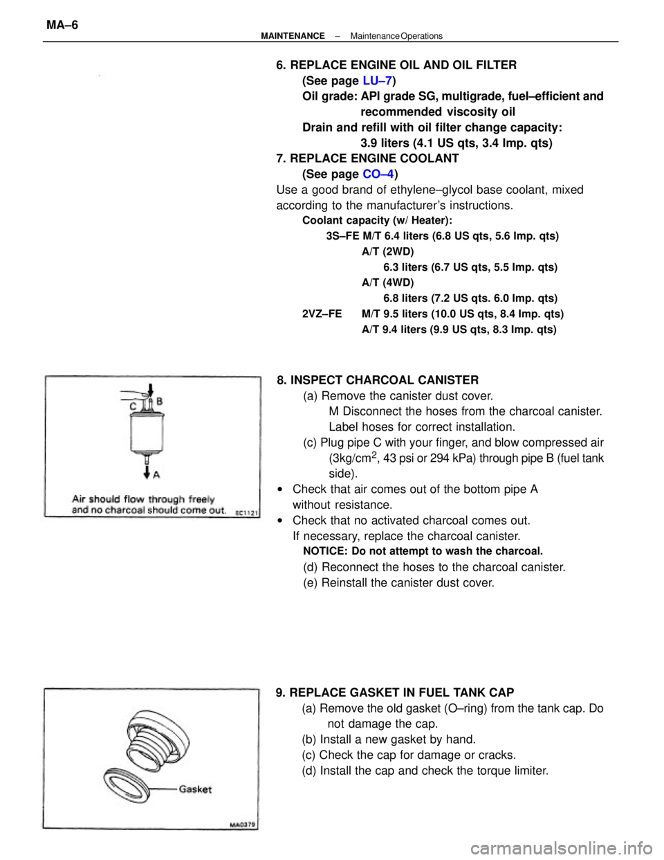
8. INSPECT CHARCOAL CANISTER
(a) Remove the canister dust cover.
M Disconnect the hoses from the charcoal canister.
Label hoses for correct installation.
(c) Plug pipe C with your finger, and blow compressed air
(3kg/cm
2, 43 psi or 294 kPa) through pipe B (fuel tank
side).
wCheck that air comes out of the bottom pipe A
without resistance.
wCheck that no activated charcoal comes out.
If necessary, replace the charcoal canister.
NOTICE: Do not attempt to wash the charcoal.
(d) Reconnect the hoses to the charcoal canister.
(e) Reinstall the canister dust cover.
9. REPLACE GASKET IN FUEL TANK CAP
(a) Remove the old gasket (O±ring) from the tank cap. Do
not damage the cap.
(b) Install a new gasket by hand.
(c) Check the cap for damage or cracks.
(d) Install the cap and check the torque limiter.
± MAINTENANCEMaintenance OperationsMA±6
Page 2213 of 2389
Front and rear brake
Pad thickness
Disc thickness
Disc runout
Parking brake
Lining thickness
Drum inside diameter
Front axle and suspension
Ball joint vertical play
Steering wheel freeplay
Torque specifications
Front seat mount bolts
Strut/stabilizer bar bracket x Body
Engine mounting center member x Body
Front suspension lower crossmember x Body
Rear suspension lower crossmember x Body
MAINTENANCE
Engine
Engine oil capacity (Drain and refill with oil fitter change)
Gap
Firing order
Valve clearance Coolant capacity 1w/ Heater) Drive belt tension
Alternator
Spark plug
Type
Chassis
PS pump
± SERVICE SPECIFICATIONSMaintenanceA±2
Page 2225 of 2389
Engine coolant x Drain plug
Water pump x Water pump cover
Water pump x Cylinder head
Water by±pass pipe X Water pump
Water inlet housing x Water pump
Oil cooler x Radiator tower tank
Cylinder block x Drain plug
Water pump x Cylinder block
Water inlet x Water pump
Water inlet pipe x Alternator belt adjusting bar
LUBRICATION SYSTEM (3S±FE)
SpecificationsTorque Specifi
cations (3S±FE)
COOLING SYSTEM
Specifications
Torque Specifications (2VZ±FE)
Valve opening temperature
Valve lift at 95°C (203°F) Relief valve opening pressure
Engine coolant capacityEngine coolant capacity
at Idling
at 3,040 rpm
STD
Limit
STD
Limit Body clearance .See page A±20 STD
Limit
Part tightened
Part tightenedSee page A±2
Tip clearance3S±FE
2VZ±FE
Oil pressureThermostat
Oil pumpRadiator
± SERVICE SPECIFICATIONSCooling SystemA±17