Page 295 of 2389

HYDRAULIC TEST
PREPARATION
(a) Warm up the transaxle fluid.
(b) Remove the transaxle case test plug and connect the hydraulic pressure gauge.
SST 09992±00094 (Oil pressure gauge)
NOTICE:
wPerform the test at normal operating fluid temperature (122 ±176°F or 50 ± 80°C).
wThe line pressure test should always be carried out in pairs. One should observe the conditions
of wheels or wheel stoppers outside the vehicle while the other is performing the test.
MEASURE LINE PRESSURE
(a) Fully apply the parking brake and chock the four wheels.
(b) Start the engine and check idling rpm.
(e) Step down strongly on the brake pedal with your left foot and shift into D range.
(d) Measure the line pressure when the engine is idling.
(e) Press the accelerator pedal all the way down. Quickly read the highest line pressure when engine
speed reaches stall speed.
(f) In the same manner, perform the test in R range.
If the measured pressure are not up to specified values, recheck the throttle cable adjustment and
perform a retest.
kg/cm (psi, kPa)
Line pressure
R range D range
Idling
IdlingStall
Stall
± AUTOMATIC TRANSAXLETroubleshooting (Mechanical System Tests) (A140L and
A140E)AT±40
Page 454 of 2389

Preliminary Check
1. CHECK TRANSAXLE FLUID LEVEL
HINT:
The vehicle must have been driven so that the engine
and transaxle are at normal operating temperature.
(Fluid temperature: 158 ± 176
°F or 70 ± 80°C)
(a) Park the vehicle on a level surface, set the parking brake.
(b) With the engine idling, shift the shift lever into all
positions from P to L position and return to P position.
HINT: Depress the brake pedal.
(e) Pull out the transaxle dipstick and wipe it clean.
(d) Push it back fully into the tube.
(e) Pull it out and check that the fluid level is in the HOT
range.
If the level is at the low side, add fluid.
Fluid type: A540E ATF DEXRON� II
A540H ATF Type T (08886±00405) or equivalent
NOTICE: Do not overfill.
2. (A540H)
CHECK TRANSFER OIL LEVEL
(a) Park the vehicle on a level surface, set the parking brake.
(b) Pull out the transfer dipstick and wipe it clean.
(e) Push it back fully into the tube.
(d) Pull it out and check the oil level as shown in the illustra-
tion.
Oil type: Transaxle oil E50 (08885±80206), AP GL5,
SAE 75W ± 90 or equivalent
NOTICE: Do not overfill.
± AUTOMATIC TRANSAXLETroubleshooting (Preliminary Check) (A540E and A540H)AT±199
Page 455 of 2389

Capacity:
Dry fill: 7.0 liter (7.4 US qts, 6.2 Imp. qts)
Drain and refill:
3.3 liter (3.5 US qts, 2.9 Imp. qts)
(d) Start the engine and shift the selector into all positions
from P through L and then shift into P.
(e) With the engine idling, check the fluid level. Add fluid
up to the COOL level on the dipstick.
(f) Check the fluid level with the normal fluid temperature
(158 ± 1765 F or 70 ± 805C) ±and add as
necessary.
NOTICE: Do not overfill.
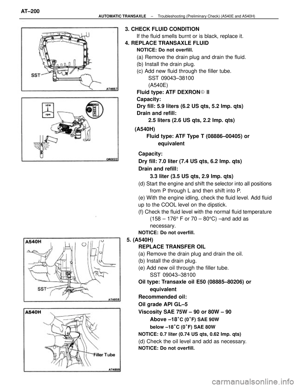
5. (A540H)
REPLACE TRANSFER OIL
(a) Remove the drain plug and drain the oil.
(b) Install the drain plug.
(e) Add new oil through the filler tube.
SST 09043±38100
Oil type: Transaxle oil E50 (08885±80206) or
equivalent
Recommended oil:
Oil grade API GL±5
Viscosity SAE 75W ± 90 or 80W ± 90
Above ±18
°C (0°F) SAE 90W
below ±18°C (0°F) SAE 80W
NOTICE: 0.7 liter (0.74 US qts, 0.62 Imp. qts)
(d) Check the oil level and add as necessary.
NOTICE: Do not overfill.
3. CHECK FLUID CONDITION
If the fluid smells burnt or is black, replace it.
4. REPLACE TRANSAXLE FLUID
NOTICE: Do not overfill.
(a) Remove the drain plug and drain the fluid.
(b) Install the drain plug.
(c) Add new fluid through the filler tube.
SST 09043±38100
(A540E)
Fluid type: ATF DEXRON� ll
Capacity:
Dry fill: 5.9 liters (6.2 US qts, 5.2 Imp. qts)
Drain and refill:
2.5 liters (2.6 US qts, 2.2 Imp. qts)
(A540H)
Fluid type: ATF Type T (08886±00405) or
equivalent
± AUTOMATIC TRANSAXLETroubleshooting (Preliminary Check) (A540E and A540H)AT±200
Page 460 of 2389

HYDRAULIC TEST
PREPARATION
(a) Warm up the transaxle fluid.
(b) Remove the transaxle case test plug and connect the hydraulic pressure gauge.
SST 09992±00094 (Oil pressure gauge)
NOTICE:
wPerform the test at normal operating fluid temperature (122 ± 176°F or 50 ± 80°C)
wThe line pressure test should always be carried out in pairs. One should observe the conditions of
wheels or wheel stoppers outside the vehicle while the other is performing the test.
MEASURE LINE PRESSURE
(a) Fully apply the parking brake and chock the four wheels.
(b) Start the engine and check idling rpm.
(c) Step down strongly on the brake pedal with your left foot and shift into D range.
(d) Measure the line pressure when the engine is idling.
(e) Press the accelerator pedal all the way down. Quickly read the highest line pressure when engine
speed reaches stall speed.
(f) In the same manner, perform the test in R range.
(A540E)
kg/cm2 (psi, kPa)
Line pressure
D rangeR range
Idling
IdlingStallStall
± AUTOMATIC TRANSAXLETroubleshooting (Mechanical System Tests) (A540E and
A540H)AT±224
Page 696 of 2389

Precautions for storing moulding material:
wStore in a cool place, avoiding direct sunlight, high
temperatures and dust.
wThe moulding is of polyvinyl chloride, so do not allow it to
come in contact with thinner or other solvent, open flame,
or boiling water.
wThe storage time for the moulding, adhesive and Primer T
is limited to about 9 months.
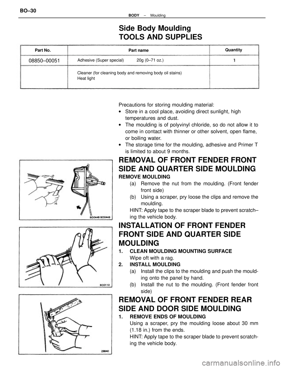
REMOVAL OF FRONT FENDER FRONT
SIDE AND QUARTER SIDE MOULDING
REMOVE MOULDING
(a) Remove the nut from the moulding. (Front fender
front side)
(b) Using a scraper, pry loose the clips and remove the
moulding.
HINT: Apply tape to the scraper blade to prevent scratch±
ing the vehicle body.
INSTALLATION OF FRONT FENDER
FRONT SIDE AND QUARTER SIDE
MOULDING
1. CLEAN MOULDING MOUNTING SURFACE
Wipe oft with a rag.
2. INSTALL MOULDING
(a) Install the clips to the moulding and push the mould-
ing onto the panel by hand.
(b) Install the nut to the moulding. (Front fender front
side)
REMOVAL OF FRONT FENDER REAR
SIDE AND DOOR SIDE MOULDING
1. REMOVE ENDS OF MOULDING
Using a scraper, pry the moulding loose about 30 mm
(1.18 in.) from the ends.
HINT: Apply tape to the scraper blade to prevent scratch-
ing the vehicle body.
Side Body Moulding
TOOLS AND SUPPLIES
Cleaner (for cleaning body and removing body oil stains)
Heat lightAdhesive (Super special) 20g (0±71 oz.)
08850±00051
Quantity
Part name Part No.
± BODYMouldingBO±30
Page 777 of 2389

Replace fuse and check for short
Replace bulb
Check switch
Check switch
Check switch
Check relay
Repair a s necessary ºDOMEº fuse blown
Bulb burned out
Door courtesy switch faulty
Unlock warning switch faulty
Buckle switch faulty
Seat belt warning relay faulty
Wiring or ground faultyºGAUGEº fuse blown
Bulb burned out
Brake fluid level warning switch faulty
Parking brake switch faulty
Wiring or ground faultyReplace fuse and check for short
Replace bulb
Check switch
Check switch
Repair as necessary ºGAUGEº fuse blown
Water temperature gauge faulty
Water temperature sender gauge faulty
Wiring or ground faulty
ºGAUGEº fuse blown
Buibburned out
oil pressure warning switch faulty
Wiring or ground faultyºGAUGEº fuse blown
Bulb burned out
Fuel level warning switch faulty
Wiring or ground faulty
Replace fuse and check for short
Replace bulb
Check switch
±Repair as necessaryReplace fuse and check for short
Replace bulb
Check switch
Repair as necessary
Replace fuse and check for short
Replace bulb
Check switch
Repair as necessaryReplace fuse and check for short
Check gauge
Check sender gauge
Repair as necessaryReplace fuse .and check for short
Check gauge
Check sender gauge
Repair as necessary
COMBINATION METER
Troubleshooting
ºGAUGEº fuse blown
Bulb burned out
Door courtesy switch faulty
Wiring or ground faultyReplace fuse and check for short
Check tachometer
Repair as necessary
ºGAUGEº fuse blown
Fuel gauge faulty
Sender gauge faulty
Wiring or ground faultyºGAUGEº fuse blown
Tachometer faulty
Wiring faulty
Low oil pressure warning
light does not lightWater temperature
gauge does not
operate
Seat belt warning
does not operate
(Canada)Tachometer does not
operate
Brake warning light does
not lightFuel gauge does not
operate
Open door warning light
does not lightFuel level warning light
does not light
BE±40
BE±13
BE±41
BE±41BE±3
BE±38
BE±39BE±3
BE±36
BE±37 Possible cause
BE±3
BE±36
BE±40
BE±40 Problem
Remedy
BE±40BE±39BE±37Page
BE±3BE±3
BE±3
BE±3
BE±3
± BODY ELECTRICAL SYSTEMCombination MeterBE±31
Page 778 of 2389
Light Control Rheostat
TAIL Fuse
IGN Fuse
Water Temperature Sender Gauge
Ground
Seat Beh Warning Relay
Brake Fluid Level Warning Switch and Parking
Brake Switch
CHARGE Fuse
TCCS ECU
A.B.S. ECU
Cruise Control ECU and ECT ECU
Ground
Fuel Sender Gauge Terminal 3
Fuel Sender Gauge Terminal 2
GAUGE Fuse
DOME Fuse
Door Courtesy Switch
Low Oil Pressure Switch
Light Failure Sensor
Combination Meter and Gauges
(w/o Tachometer)
Turn Signal Switch Terminal 28
Ground
Turn Signal Switch Terminal 25
Turn Signal Switch Terminal 23 (USA)
HEAD±HI (RH) Fuse (CANADA)
A/T Oil Temperature Switch
COMBINATION METER CIRCUIT
Wiring Connector Side
No.
± BODY ELECTRICAL SYSTEMCombination MeterBE±32
Page 779 of 2389
Light Control Rheostat
TAIL Fuse
IGN Fuse
Water Temperature Sender Gauge
Ground
Seat Belt Warning Relay
Brake Fluid Level Warning Switch and Parking
Brake Switch
CHARGE Fuse
TCCS ECU ,
A. B. S. ECU
Cruise Control ECU and ECT ECU
Ground
Fuel Sender Gauge Terminal 3
Fuel Sender Gauge Terminal 2
. GAUGE Fuse
DOME Fuse
Door Courtesy Switch
Low Oil Pressure Switch
Light Failure Sensor
Turn Signal Switch Terminal 28
Ground
Turn Signal Switch Terminal 25
Turn Signal Switch Terminal 23 (USA)
HEAD±HI (RH) Fuse (CANADA)
A/T Oil Temperature Switch
Igniter
Combination Meter and Gauges
(w/ Tachometer)
COMBINATION METER CIRCUIT
Wiring Connector Side
No.
± BODY ELECTRICAL SYSTEMCombination MeterBE±33