Page 1233 of 2389
2. REMOVE VALVES
(a) Using SST, compress the valve spring and remove the two
keepers.
SST 09202±70010
(b) Remove the spring retainer, valve spring, valve and spring
seat.
DISASSEMBLY OF CYLINDER HEAD
(See page EM±47)
1. REMOVE VALVE LIFTERS AND SHIMS
HINT: Arrange the valves, valve springs, spring seats
and spring retainers in correct order. HINT: Arrange the valve lifters and shims in correct or-
der.
(c) Using needle±nose pliers, remove the oil seal.
± ENGINE MECHANICALCylinder Head (3S±FE)EM±56
Page 1238 of 2389

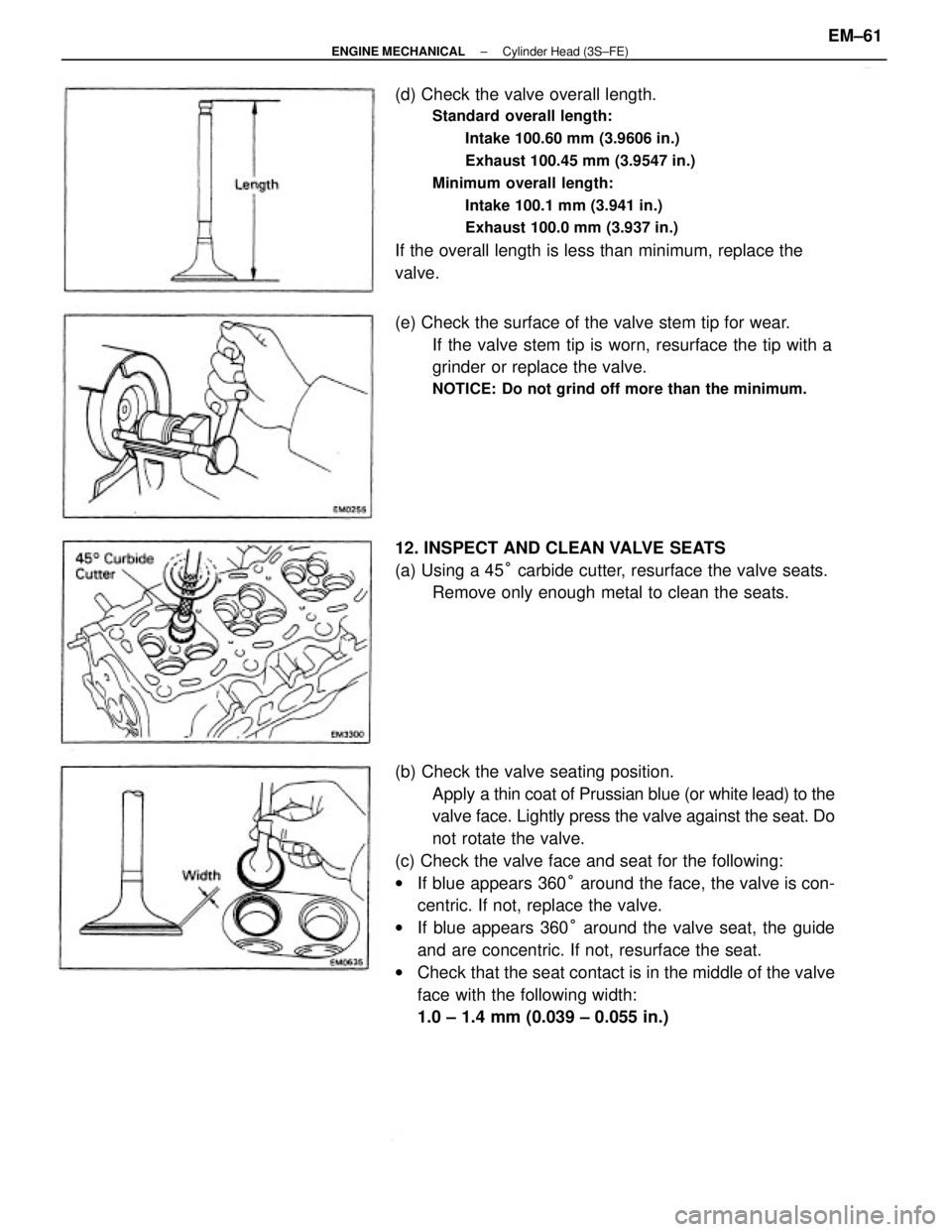
(b) Check the valve seating position.
Apply a thin coat of Prussian blue (or white lead) to the
valve face. Lightly press the valve against the seat. Do
not rotate the valve.
(c) Check the valve face and seat for the following:
wIf blue appears 360° around the face, the valve is con-
centric. If not, replace the valve.
wIf blue appears 360° around the valve seat, the guide
and are concentric. If not, resurface the seat.
wCheck that the seat contact is in the middle of the valve
face with the following width:
1.0 ± 1.4 mm (0.039 ± 0.055 in.) (d) Check the valve overall length.
Standard overall length:
Intake 100.60 mm (3.9606 in.)
Exhaust 100.45 mm (3.9547 in.)
Minimum overall length:
Intake 100.1 mm (3.941 in.)
Exhaust 100.0 mm (3.937 in.)
If the overall length is less than minimum, replace the
valve.
(e) Check the surface of the valve stem tip for wear.
If the valve stem tip is worn, resurface the tip with a
grinder or replace the valve.
NOTICE: Do not grind off more than the minimum.
12. INSPECT AND CLEAN VALVE SEATS
(a) Using a 45° carbide cutter, resurface the valve seats.
Remove only enough metal to clean the seats.
± ENGINE MECHANICALCylinder Head (3S±FE)EM±61
Page 1239 of 2389
13. INSPECT VALVE SPRINGS
(a) Using a steel square, measure the squareness of the valve
spring.
Maximum squareness: 2.0 mm (0.075 in.)
If squareness is greater than maximum, replace the valve
spring.
(b) Using calipers, measure the free length of the valve
spring.
Free length: 45.0 mm (1.772 in.)
If the free length is not as specified, replace the valve
spring. (d) Hand±lap the valve and valve seat with an abrasive
compound.
(e) After hand±lapping, clean the valve and valve seat. If not, correct the valve seats as follows:
(1) If the seating is too high on the valve face, use 30°
and 45° cutters to correct the seat.
(2) If the seating is too low on the valve face, use 75°
and 45° cutters to correct the seat.
± ENGINE MECHANICALCylinder Head (3S±FE)EM±62
Page 1261 of 2389
2. REMOVE VALVES
(a) Using SST, compress the valve spring and remove the two
keepers.
SST 09202±70010
(b) Remove the spring retainer, valve spring, valve and spring
seat.
DISASSEMBLY OF CYLINDER HEADS
(See page EM±75)
1 . REMOVE VALVE LIFTERS AND SHIMS
HINT: Arrange the valves, valve springs, spring seats
and spring retainers in correct order.
(c) Using needle±nose pliers, remove the oil seal. HINT: Arrange the valve lifters and shims in correct or-
der.
± ENGINE MECHANICALCylinder Heads (2VZ±FE)EM±84
Page 1266 of 2389

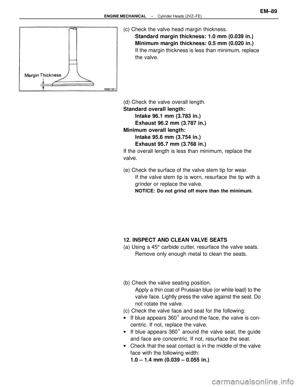
(b) Check the valve seating position.
Apply a thin coat of Prussian blue (or white lead) to the
valve face. Lightly press the valve against the seat. Do
not rotate the valve.
(c) Check the valve face and seat for the following:
wIf blue appears 360° around the face, the valve is con-
centric. If not, replace the valve.
wIf blue appears 360° around the valve seat, the guide
and face are concentric. If not, resurface the seat.
wCheck that the seat contact is in the middle of the valve
face with the following width:
1.0 ± 1.4 mm (0.039 ± 0.055 in.) (d) Check the valve overall length.
Standard overall length:
Intake 96.1 mm (3.783 in.)
Exhaust 96.2 mm (3.787 in.)
Minimum overall length:
Intake 95.6 mm (3.754 in.)
Exhaust 95.7 mm (3.768 in.)
If the overall length is less than minimum, replace the
valve. (c) Check the valve head margin thickness.
Standard margin thickness: 1.0 mm (0.039 in.)
Minimum margin thickness: 0.5 mm (0.020 in.)
If the margin thickness is less than minimum, replace
the valve.
(e) Check the surface of the valve stem tip for wear.
If the valve stem tip is worn, resurface the tip with a
grinder or replace the valve.
NOTICE: Do not grind off more than the minimum.
12. INSPECT AND CLEAN VALVE SEATS
(a) Using a 455 carbide cutter, resurface the valve seats.
Remove only enough metal to clean the seats.
± ENGINE MECHANICALCylinder Heads (2VZ±FE)EM±89
Page 1267 of 2389
13. INSPECT VALVE SPRINGS
(a) Using a steel square, measure the squareness of the valve
spring.
Maximum squareness: 2.0 mm (0.075 in.)
if squareness is greater than maximum, replace the valve
spring.
(b) Using calipers, measure the free length of the valve
spring.
Free length: 42.6 mm (1.677 in.)
If the free length is not as specified, replace the valve
spring. If not, correct the valve seats as follows:
111 If the seating is too high on the valve face, use
30° and 45° cutters to correct the seat.
(d) Hand±lap the valve and valve seat with an abrasive
compound.
After hand±lapping, clean the valve and valve seat. (2) If the seating is too low on the valve face, use
60° and 45° cutters to correct the seat.
± ENGINE MECHANICALCylinder Heads (2VZ±FE)EM±90
Page 1914 of 2389

GENERAL MAINTENANCE
These are the maintenance and inspection items
which are considered to be the owner's responsibility,
They can be performed by the owner or he
can have then done at a service shop. These items
include those which should be checked on a daily ba-
sis, those which, in most cases, do not require
(special) tools and those which are considered to be
reasonable for the owner to perform.
Items and procedures for general maintenance are as
follows:
OUTSIDE VEHICLE
1. TIRES
(a) Check the pressure with a gauge. Adjust
if necessary.
(b) Check for cuts, damage or excessive wear.
2. WHEEL NUTS
When checking the tires, check the nuts for looseness
or for missing nuts. If necessary,
tighten them.
3. TIRE ROTATION
It is recommended that tires be rotated every
7,500 miles (12,000 km).
4. WINDSHIELD WIPER BLADES
Check for wear or cracks whenever they do not wipe
clean. Replace if necessary.
5. FLUID LEAKS
(a) Check underneath for leaking fuel, oil, water or
other fluid.
(b) If you smell gasoline fumes or notice any leak,
have the cause found and corrected.
6. DOORS AND ENGINE HOOD
(a) Check that all doors including the trunk lid and
back door operate smoothly, and that all
latches lock securely.
(b) Check that the engine hood secondary latch se-
cures the hood from opening when the prima-
ry latch is released.
INSIDE VEHICLE
7. LIGHTS
(a) Check that the headlights, stop lights, taillights,
turn signal lights, and other
lights are all working.
(b) Check the headlight aiming.8. WARNING LIGHTS AND BUZZERS
Check that all warning lights and buzzers func-
tion properly.
9. HORN
Check that it is working.
10. WINDSHIELD GLASS
Check for scratches, pits or abrasions.
11. WINDSHIELD WIPER AND WASHER
(a) Check operation of the wipers and washer.
(b) Check that the wipers do not streak.
12. WINDSHIELD DEFROSTER
Check that air comes out from the defroster out-
let when operating the heater or air conditioner
at defroster mode.
13. REAR VIEW MIRROR
Check that it is mounted securely.
14. SUN VISORS
Check that they move freely and are mounted
securely.
15. STEERING WHEEL
Check that it has the specified freeplay. Be alert
for changes in steering condition, such as hard
steering, excessive freeplay or strange noise.
16. SEATS
(a) Check that all front seat controls such as
seat adjusters, seatback recliner, etc.
operate smoothly.
(b) Check that a11 latches lock securely in
any position.
(c) Check that the locks hold securely in any
latched position.
(d) Check that the head restraints move up
and down smoothly and that the locks
hold securely in any latched position.
(e) For folding±down rear seat backs, check
that the latches lock securely.
17. SEAT BELTS
(a) Check that the seat belt system such as
buckles, retractors and anchors operate
properly and smoothly.
(b) Check that the belt webbing is not cut,
frayed, worn or damaged.
± MAINTENANCEGeneral MaintenanceMA±16
Page 1926 of 2389

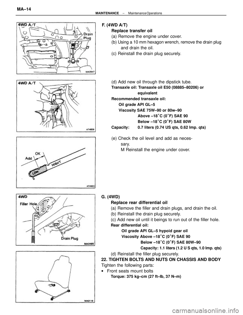
G. (4WD)
Replace rear differential oil
(a) Remove the filler and drain plugs, and drain the oil.
(b) Reinstall the drain plug securely.
(c) Add new oil until it beings to run out of the filler hole.
Rear differential oil:
Oil grade API GL±5 hypoid gear oil
Viscosity Above ±18°C (0°F) SAE 90
Below ±18°C (0°F) SAE 80W±90
Capacity: 1.1 liters (1.2 U S qts, 1.0 Imp. qts)
(d) Reinstall the filler plug securely.
22. TIGHTEN BOLTS AND NUTS ON CHASSIS AND BODY
Tighten the following parts:
wFront seats mount bolts
Torque: 375 kg±cm (27 ft±Ib, 37 N±m)
(d) Add new oil through the dipstick tube.
Transaxle oil: Transaxle oil E50 (08885±80206) or
equivalent
Recommended transaxle oil:
Oil grade API GL±5
Viscosity SAE 75W±90 or 80w±90
Above ±18°C (0°F) SAE 90
Below ±18°C (0°F) SAE 80W
Capacity: 0.7 liters (0.74 US qts, 0.62 Imp. qts)
F. (4WD A/T)
Replace transfer oil
(a) Remove the engine under cover.
(b) Using a 10 mm hexagon wrench, remove the drain plug
and drain the oil.
(c) Reinstall the drain plug securely.
(e) Check the oil level and add as neces-
sary.
M Reinstall the engine under cover.
± MAINTENANCEMaintenance OperationsMA±14