1986 TOYOTA CAMRY V20 tire pressure
[x] Cancel search: tire pressurePage 298 of 2389

ROAD TEST (A140E)
NOTICE: Perform the test at normal operating fluid
temperature (122 ± 176°F or 50 ± 84°C). .
1. D RANGE TEST IN NORM AND PWR PATTERN
RANGES
Shift into the D range and hold the accelerator pedal
constant at the full throttle valve opening position.
Check the following:
(a) 1±2, 2±3 and 3±O/D up±shifts should take place, and
shift points should conform to those shown in the au-
tomatic shift schedule. (See page AT±49)
Conduct a test under both Normal and Power patterns.
HINT:
There is no O/D up±shift when coolant temperature is
below 122
°F (50°C).
There is no lock±up when the vehicle speed is 10 km/h (6
mph) less than the set cruise control speed.
EVALUATION
(1) If there is no 1 ± 2 up±shift:
wNo. 2 solenoid is stuck
w1±2 shift valve is stuck
(2) If there is no 2 ± 3 up±shift:
w No. 1 solenoid is stuck
w2±3 shift valve is stuck
(3) If there is no 3 ± O/D up±shift:
w3±O/D shift valve is stuck
(4) If the shift point is defective:
wThrottle valve, 1±2 shift valve, 2±3 .shift valve, 3±
wO/D shift valve etc., are defective
(5) If the lock±up is defective:
wLock±up solenoid is stuck
wLock±up relay valve is stuck
(b) In the same manner, check the shock and slip at the 1
±2, 2 ± 3 and 3 ± O/D up±shifts.
EVALUATION
If the shock is excessive:
wLine pressure is too high
wAccumulator is defective
wCheck ball is defective
(c) Run at the D range lock±up or O/D gear and check for
abnormal noise and vibration.
HINT: The check for the cause of abnormal noise and
vibration must be make with extreme care as it could
also be due to loss of balance in the drive shaft, tire,
torque converter, etc.
± AUTOMATIC TRANSAXLETroubleshooting (Mechanical System Tests) (A140L and
A140E)AT±43
Page 301 of 2389

ROAD TEST (A140L)
NOTICE: Perform the test at norrnal operating fluid tem-
perature (122 ± 176°F or 50 ± 80°C).
1. D RANGE TEST
Shift into the D range and hold the accelerator pedal
constant at the full throttle valve opening position.
Check the following:
(a) 1±2, 2±3 and 3±0ID up±shifts should take place, and
shift points should conform to those shown in the au-
tomatic shift schedule. (See page AT±49)
EVALUATION
(1) If there is no 1 ±2 up±shift:
wGovernor valve is defective
w 1±2 shift valve is stuck
(2) if there is no 2 ±3 up±shift:
w 2±3 shift valve is stuck .
(3) If there is no 3 ± O/D up±shift:
w3±O/D shift valve is stuck
wO/D solenoid is defective
(4) If the shift point is defective:
wThrottle cable is out±of±adjustment
wThrottle valve, 1±2 shift valve, 2±3 shift valve, 3±
O/D shift valve etc., are defective
(b) In the same manner, check the shock and slip at the
1± 2, 2 ± 3 and 3 ± O/D up±shifts.
EVALUATION
If the shock is excessive:
wLine pressure is too high
Accumulator is defective
wCheck ball is defective
(c) Run at the D range lock±up or O/D gear and check for
abnormal noise and vibration.
HINT: The check for the cause of abnormal noise and
vibration must be make with extreme care as it could
also be due to loss of balance in the drive shaft, tire,
torque converter, etc.
± AUTOMATIC TRANSAXLETroubleshooting (Mechanical System Tests) (A140L and
A140E)AT±46
Page 463 of 2389

ROAD TEST (A540E and A540H)
NOTICE: Perform the test at normal operating fluid temperature
(122 ± 176°F or 50 ± 80°C).
1. D RANGE TEST IN NORM AND PWR PATTERN
RANGES
Shift into the D range and hold the accelerator pedal
constant at the full throttle valve opening position.
Check the following:
(a) 1±2, 2±3 and 3±O/D up±shifts should take place, and shift
points should conform to those shown in the automatic
shift schedule. (See page AT±230)
Conduct a test under both Normal and Power. patterns.
HINT:
wThere is no O/D up±shift and lock±up when the coolant
temp. is below 140
°F (60°C) (A540E) or 122°I= (50°C)
(A540H).
wWhen the coolant temp. is below 140°F (600C) or
122°F (50°C) (A540H), the shift point is lower than specified in
the automatic shift schedule.
EVALUATION
(1) If there is no 1 ± 2 up±shift:
wNo. 2 solenoid is stuck
w1±2 shift valve is stuck
(2) If there is no 2 ± 3 up±shift:
wNo. 1 solenoid is stuck
w2±3 shift valve is stuck
(3) If there is no 3 ± O/D up±shift:
w3±4 shift valve is stuck
(4) If the shift point is defective:
wThrottle valve, 1±2 shift valve, 2±3 shift valve, 3±4
shift valve etc., are defective
(5) If the lock±up is defective:
wLock±up solenoid is stuck .
wLock±up relay valve is stuck
(b) In the same manner, check the shock and slip at the 1
±2, 2 ± 3 and 3 ± O/D up±shifts.
EVALUATION
If the shock is excessive:
wLine pressure is too high
wAccumulator is defective
wCheck ball is defective
(c) Run at the D range lock±up or 0/C) gear and check for abnor-
mal noise and vibration.
HINT: The check for the cause of abnormal noise and vibra-
tion must be make with extreme care as it could also be due
to loss of balance in the drive shaft, tire, torque converter,
etc.
± AUTOMATIC TRANSAXLETroubleshooting (Mechanical System Tests) (A540E and
A540H)AT±227
Page 852 of 2389
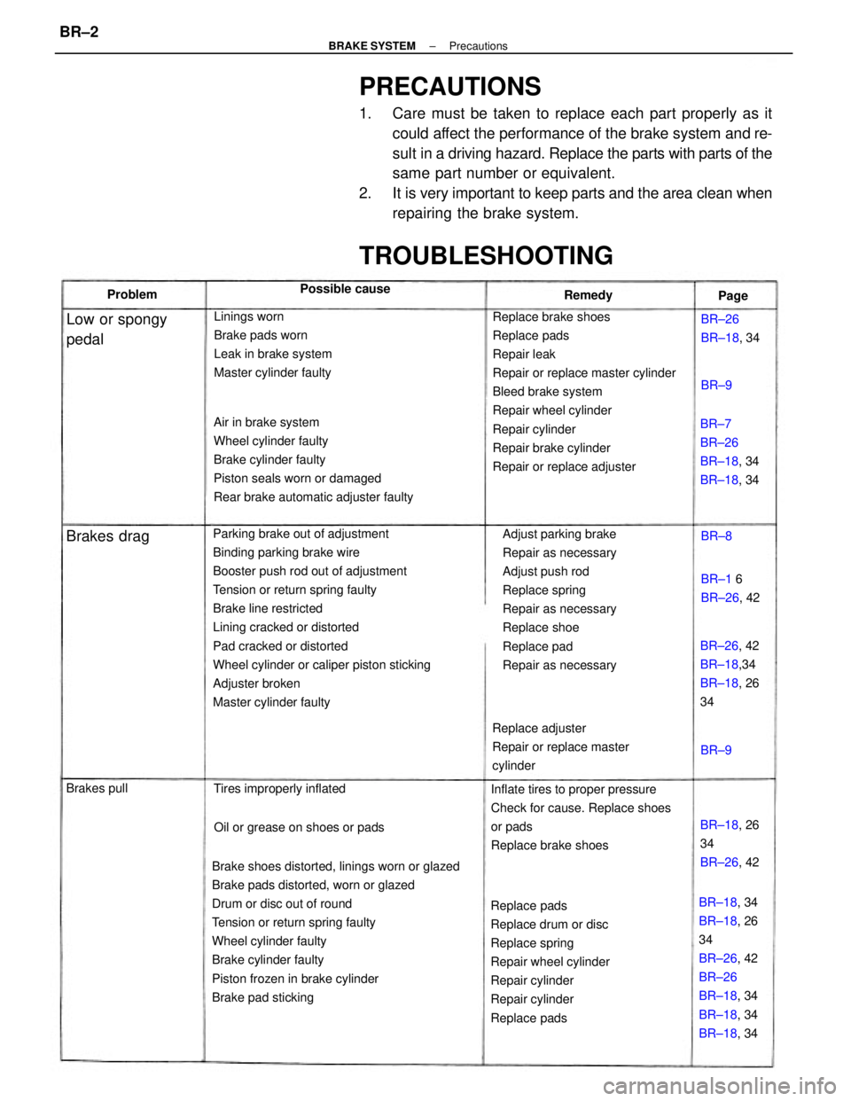
PRECAUTIONS
1. Care must be taken to replace each part properly as it
could affect the performance of the brake system and re-
sult in a driving hazard. Replace the parts with parts of the
same part number or equivalent.
2. It is very important to keep parts and the area clean when
repairing the brake system.
Parking brake out of adjustment
Binding parking brake wire
Booster push rod out of adjustment
Tension or return spring faulty
Brake line restricted
Lining cracked or distorted
Pad cracked or distorted
Wheel cylinder or caliper piston sticking
Adjuster broken
Master cylinder faulty
Brake shoes distorted, linings worn or glazed
Brake pads distorted, worn or glazed
Drum or disc out of round
Tension or return spring faulty
Wheel cylinder faulty
Brake cylinder faulty
Piston frozen in brake cylinder
Brake pad stickingReplace brake shoes
Replace pads
Repair leak
Repair or replace master cylinder
Bleed brake system
Repair wheel cylinder
Repair cylinder
Repair brake cylinder
Repair or replace adjuster Air in brake system
Wheel cylinder faulty
Brake cylinder faulty
Piston seals worn or damaged
Rear brake automatic adjuster faulty
Adjust parking brake
Repair as necessary
Adjust push rod
Replace spring
Repair as necessary
Replace shoe
Replace pad
Repair as necessary
Replace pads
Replace drum or disc
Replace spring
Repair wheel cylinder
Repair cylinder
Repair cylinder
Replace padsInflate tires to proper pressure
Check for cause. Replace shoes
or pads
Replace brake shoes Linings worn
Brake pads worn
Leak in brake system
Master cylinder faulty
BR±18, 34
BR±18, 26
34
BR±26, 42
BR±26
BR±18, 34
BR±18, 34
BR±18, 34 Replace adjuster
Repair or replace master
cylinder
TROUBLESHOOTING
BR±7
BR±26
BR±18, 34
BR±18, 34
BR±26, 42
BR±18,34
BR±18, 26
34
Oil or grease on shoes or pads Tires improperly inflated
BR±18, 26
34
BR±26, 42
Low or spongy
pedalBR±26
BR±18, 34
BR±1 6
BR±26, 42 Possible cause
Brakes drag
Brakes pullRemedy Problem
Page
BR±8
BR±9BR±9
± BRAKE SYSTEMPrecautionsBR±2
Page 853 of 2389
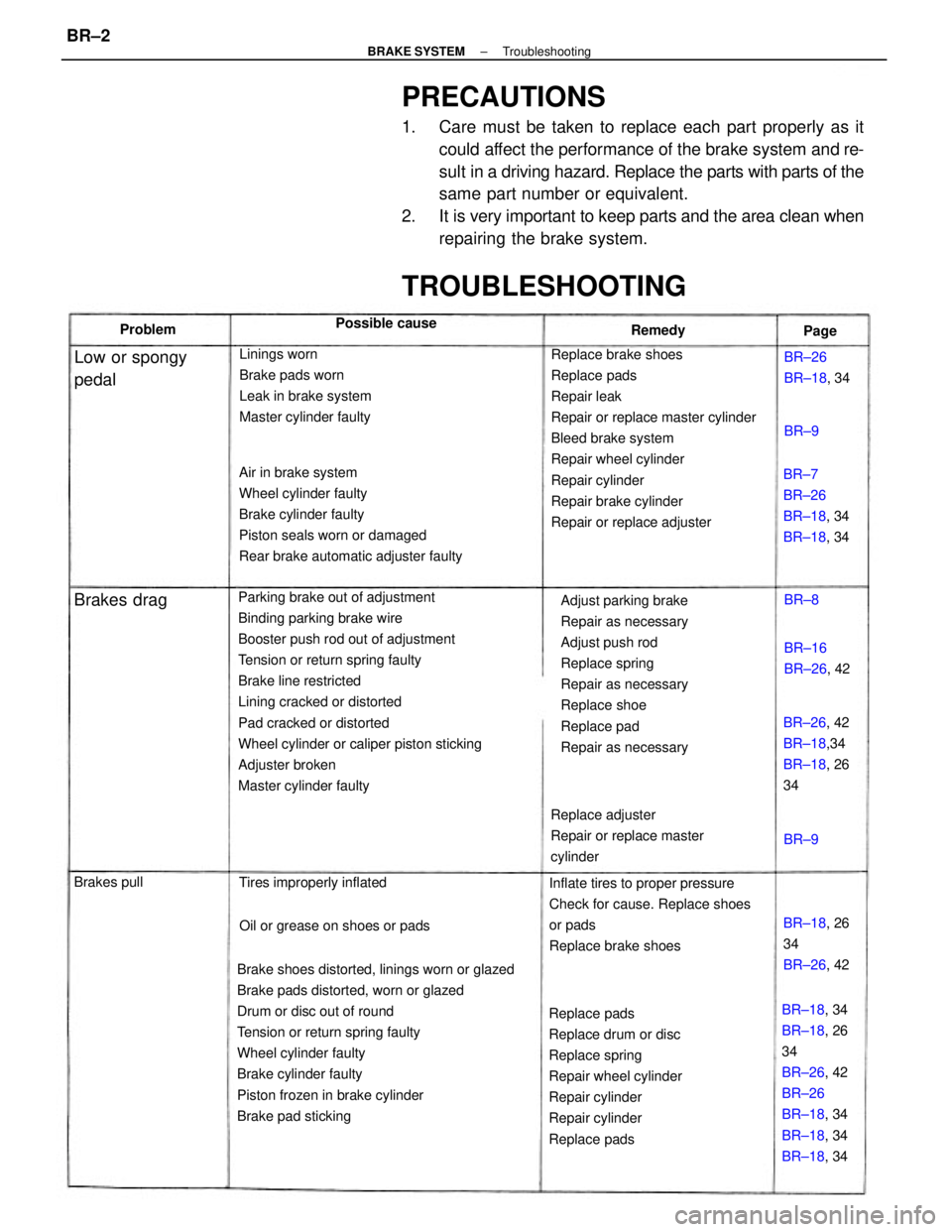
PRECAUTIONS
1. Care must be taken to replace each part properly as it
could affect the performance of the brake system and re-
sult in a driving hazard. Replace the parts with parts of the
same part number or equivalent.
2. It is very important to keep parts and the area clean when
repairing the brake system.
Parking brake out of adjustment
Binding parking brake wire
Booster push rod out of adjustment
Tension or return spring faulty
Brake line restricted
Lining cracked or distorted
Pad cracked or distorted
Wheel cylinder or caliper piston sticking
Adjuster broken
Master cylinder faulty
Brake shoes distorted, linings worn or glazed
Brake pads distorted, worn or glazed
Drum or disc out of round
Tension or return spring faulty
Wheel cylinder faulty
Brake cylinder faulty
Piston frozen in brake cylinder
Brake pad stickingReplace brake shoes
Replace pads
Repair leak
Repair or replace master cylinder
Bleed brake system
Repair wheel cylinder
Repair cylinder
Repair brake cylinder
Repair or replace adjuster Air in brake system
Wheel cylinder faulty
Brake cylinder faulty
Piston seals worn or damaged
Rear brake automatic adjuster faulty
Adjust parking brake
Repair as necessary
Adjust push rod
Replace spring
Repair as necessary
Replace shoe
Replace pad
Repair as necessary
Replace pads
Replace drum or disc
Replace spring
Repair wheel cylinder
Repair cylinder
Repair cylinder
Replace padsInflate tires to proper pressure
Check for cause. Replace shoes
or pads
Replace brake shoes Linings worn
Brake pads worn
Leak in brake system
Master cylinder faulty
BR±18, 34
BR±18, 26
34
BR±26, 42
BR±26
BR±18, 34
BR±18, 34
BR±18, 34 Replace adjuster
Repair or replace master
cylinder
TROUBLESHOOTING
BR±7
BR±26
BR±18, 34
BR±18, 34
BR±26, 42
BR±18,34
BR±18, 26
34
Oil or grease on shoes or pads Tires improperly inflated
BR±18, 26
34
BR±26, 42
Low or spongy
pedalBR±26
BR±18, 34
BR±16
BR±26, 42 Possible cause
Brakes drag
Brakes pullRemedy Problem
Page
BR±8
BR±9BR±9
± BRAKE SYSTEMTroubleshootingBR±2
Page 1186 of 2389
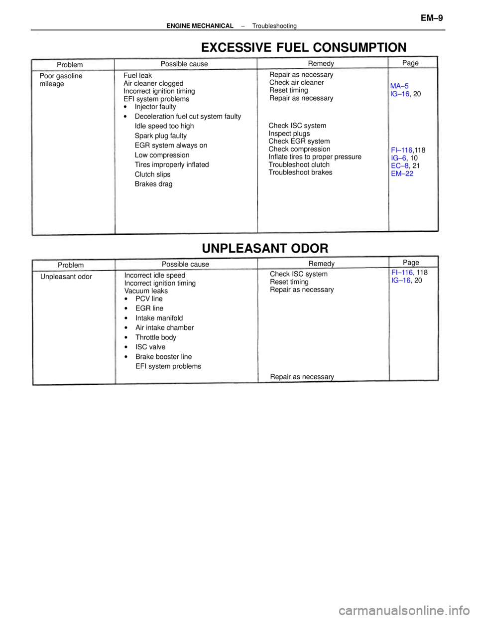
Fuel leak
Air cleaner clogged
Incorrect ignition timing
EFI system problems
wInjector faulty
wDeceleration fuel cut system faulty
Idle speed too high
Spark plug faulty
EGR system always on
Low compression
Tires improperly inflated
Clutch slips
Brakes drag
Incorrect idle speed
Incorrect ignition timing
Vacuum leaks
wPCV line
wEGR line
wIntake manifold
wAir intake chamber
wThrottle body
wISC valve
wBrake booster line
EFI system problemsCheck ISC system
Inspect plugs
Check EGR system
Check compression
Inflate tires to proper pressure
Troubleshoot clutch
Troubleshoot brakesRepair as necessary
Check air cleaner
Reset timing
Repair as necessary
EXCESSIVE FUEL CONSUMPTION
Check ISC system
Reset timing
Repair as necessaryFI±116,118
IG±6, 10
EC±8, 21
EM±22
UNPLEASANT ODOR
Poor gasoline
mileage
FI±116, 118
IG±16, 20
Repair as necessaryMA±5
IG±16, 20
Unpleasant odorPossible cause Possible cause
Problem
ProblemRemedy
RemedyPage Page
± ENGINE MECHANICALTroubleshootingEM±9
Page 1359 of 2389
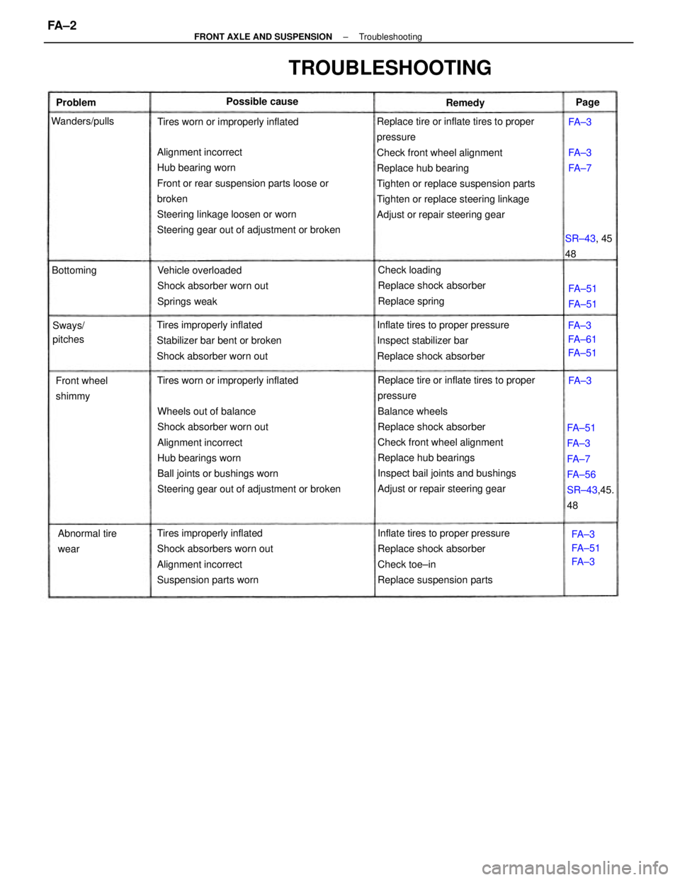
Replace tire or inflate tires to proper
pressure
Check front wheel alignment
Replace hub bearing
Tighten or replace suspension parts
Tighten or replace steering linkage
Adjust or repair steering gear
Replace tire or inflate tires to proper
pressure
Balance wheels
Replace shock absorber
Check front wheel alignment
Replace hub bearings
Inspect bail joints and bushings
Adjust or repair steering gear Wheels out of balance
Shock absorber worn out
Alignment incorrect
Hub bearings worn
Ball joints or bushings worn
Steering gear out of adjustment or broken Alignment incorrect
Hub bearing worn
Front or rear suspension parts loose or
broken
Steering linkage loosen or worn
Steering gear out of adjustment or broken
Inflate tires to proper pressure
Replace shock absorber
Check toe±in
Replace suspension parts Tires improperly inflated
Shock absorbers worn out
Alignment incorrect
Suspension parts wornInflate tires to proper pressure
Inspect stabilizer bar
Replace shock absorber Tires improperly inflated
Stabilizer bar bent or broken
Shock absorber worn outVehicle overloaded
Shock absorber worn out
Springs weakCheck loading
Replace shock absorber
Replace spring
FA±51
FA±3
FA±7
FA±56
SR±43,45.
48
TROUBLESHOOTING
Tires worn or improperly inflatedTires worn or improperly inflated
Abnormal tire
wear Front wheel
shimmyFA±3
FA±61
FA±51
FA±3
FA±51
FA±3 SR±43, 45
48 Possible cause
Sways/
pitches Wanders/pulls
FA±51
FA±51 BottomingFA±3
FA±7 Problem
RemedyPage
FA±3
FA±3
± FRONT AXLE AND SUSPENSIONTroubleshootingFA ± 2
Page 1360 of 2389
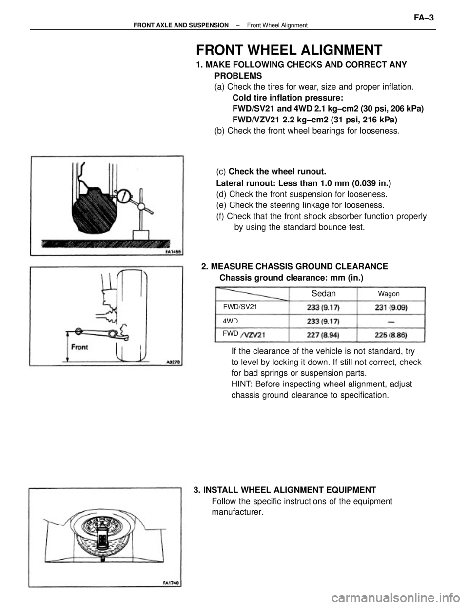
FRONT WHEEL ALIGNMENT
1. MAKE FOLLOWING CHECKS AND CORRECT ANY
PROBLEMS
(a) Check the tires for wear, size and proper inflation.
Cold tire inflation pressure:
FWD/SV21 and 4WD 2.1 kg±cm2 (30 psi, 206 kPa)
FWD/VZV21 2.2 kg±cm2 (31 psi, 216 kPa)
(b) Check the front wheel bearings for looseness.
(c) Check the wheel runout.
Lateral runout: Less than 1.0 mm (0.039 in.)
(d) Check the front suspension for looseness.
(e) Check the steering linkage for looseness.
(f) Check that the front shock absorber function properly
by using the standard bounce test.
If the clearance of the vehicle is not standard, try
to level by locking it down. If still not correct, check
for bad springs or suspension parts.
HINT: Before inspecting wheel alignment, adjust
chassis ground clearance to specification.
3. INSTALL WHEEL ALIGNMENT EQUIPMENT
Follow the specific instructions of the equipment
manufacturer. 2. MEASURE CHASSIS GROUND CLEARANCE
Chassis ground clearance: mm (in.)
FWD/SV21Wagon
Sedan
4WD
FWD
± FRONT AXLE AND SUSPENSIONFront Wheel AlignmentFA ± 3