Page 894 of 2389
DISASSEMBLY OF PARKING BRAKE
1. REMOVE REAR DISC BRAKE ASSEMBLY
(a) Remove the axle carrier mounting bolt and nut of up-
per side.
(b) Remove the two mounting bolts and remove the disc
brake assembly.
(c) Suspend the disc brake so the hose is not stretched.
4. REMOVE FRONT SHOE, ADJUSTER AND TENSION
SPRING
(a) Slide out the front shoe and remove the shoe adjust-
er.
(b) Remove the shoe strut with spring.
(c) Disconnect the tension spring and remove the front
shoe. 3. REMOVE SHOE RETURN SPRINGS
[2WD (w/o A.B.S.) and 4WD]
Using SST, remove the shoe return springs.
SST 09717±20010 2. REMOVE ROTOR DISC
HINT: If the rotor disc cannot be removed easily, return the
shoe adjuster until the wheel turns freely.
[2WD (w/ A.B.S.)]
Using needle±nose pliers, remove the shoe return springs.
± BRAKE SYSTEMRear BrakeBR±43
Page 898 of 2389
5. INSTALL TENSION SPRING, FRONT SHOE AND
ADJUSTER
(a) Install the tension spring to the rear shoe.
(b) Install the front shoe to the tension spring.
(c) Install the adjuster between the front and rear shoes.
(d) Install the shoe strut with spring. 4. INSTALL REAR SHOE
Slide in the rear shoe between the shoe hold±down spring
cup and the backing plate.
NOTICE: Do not allow oil or grease to get on the rubbing
face.
3. CONNECT PARKING BRAKE CABLE TO PARKING
BRAKE LEVER
(a) Install the shoe hold±down springs, cups and pins.
(b) Connect the parking brake cable to the parking brake
lever of the rear shoe.
(e) Slide in the front shoe between the shoe hold±down
spring cup and the backing plate. 2. APPLY HIGH TEMPERATURE GREASE TO AD-
JUSTER AS SHOWN
± BRAKE SYSTEMRear BrakeBR±47
Page 1912 of 2389

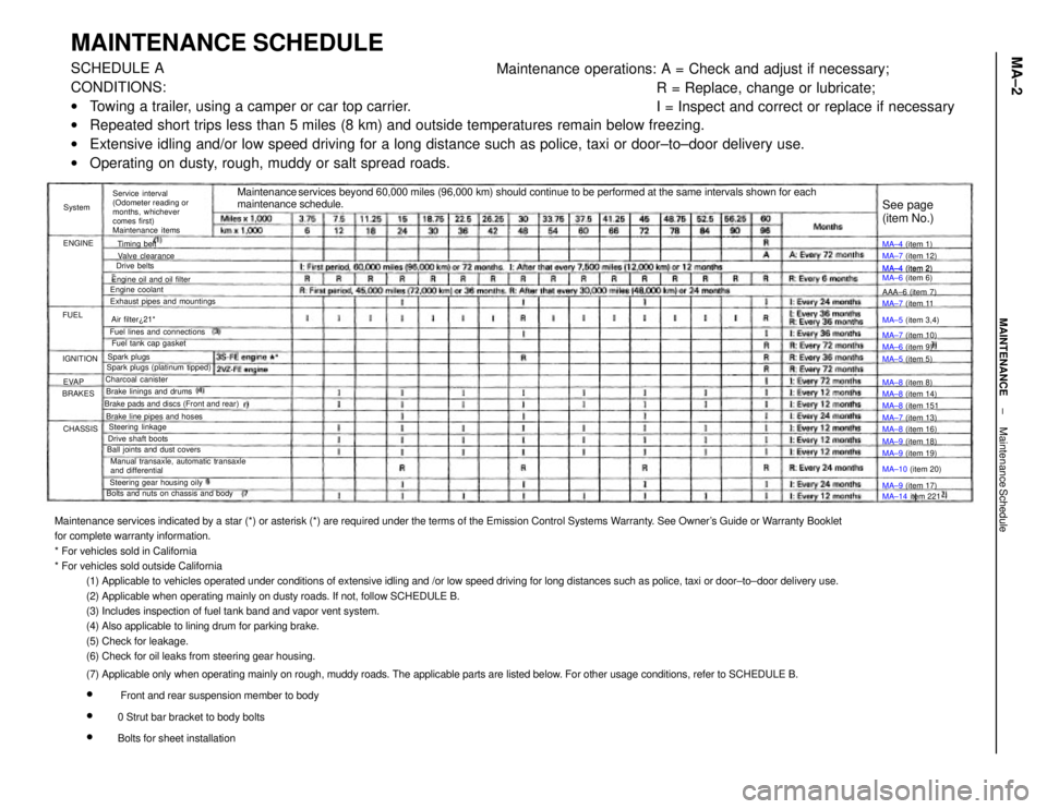
Maintenance services indicated by a star (*) or asterisk (*) are required under the terms of the Emission Control Systems Warranty. See Owner's Guide or Warranty Booklet
for complete warranty information.
* For vehicles sold in California
* For vehicles sold outside California
(1) Applicable to vehicles operated under conditions of extensive idling and /or low speed driving for long distances such as police, taxi or door±to±door delivery use.
(2) Applicable when operating mainly on dusty roads. If not, follow SCHEDULE B.
(3) Includes inspection of fuel tank band and vapor vent system.
(4) Also applicable to lining drum for parking brake.
(5) Check for leakage.
(6) Check for oil leaks from steering gear housing.
(7) Applicable only when operating mainly on rough, muddy roads. The applicable parts are listed below. For other usage conditions, refer to SCHEDULE B.
w
Front and rear suspension member to body
w
0 Strut bar bracket to body bolts
w
Bolts for sheet installation
MAINTENANCE SCHEDULESCHEDULE A
CONDITIONS:
wTowing a trailer, using a camper or car top carrier.
wRepeated short trips less than 5 miles (8 km) and outside temperatures remain below freezing.
wExtensive idling and/or low speed driving for a long distance such as police, taxi or door±to±door delivery use.
wOperating on dusty, rough, muddy or salt spread roads.Maintenance operations: A = Check and adjust if necessary;
R = Replace, change or lubricate;
I = Inspect and correct or replace if necessary
Maintenance services beyond 60,000 miles (96,000 km) should continue to be performed at the same intervals shown for each
maintenance schedule.
Service interval
(Odometer reading or
months, whichever
comes first)
Maintenance items
Manual transaxle, automatic transaxle
and differential Brake pads and discs (Front and rear)
Bolts and nuts on chassis and bodyExhaust pipes and mountings
Steering gear housing oily Brake line pipes and hosesFuel lines and connections
Ball joints and dust coversEngine oil and oil filter
Spark plugs (platinum tipped)MA±4 (item 2)
MA±6 (item 6)
Brake linings and drumsFuel tank cap gasket
Drive shaft boots
MA±14 item 221 MA±10 (item 20) MA±5 (item 3,4)
Steering linkageMA±7 (item 12)
MA±8 (item 14) Valve clearance
MA±8 (item 16)
MA±9 (item 19) MA±7 (item 13) MA±7 (item 11
MA±7 (item 10)
MA±9 (item 18) Charcoal canister
MA±9 (item 17) MA±8 (item 151
See page
(item No.)
Engine coolant
MA±6 (item 9) MA±4 (item 1)
MA±4 (item 2)
MA±5 (item 5)
MA±8 (item 8) AAA±6 (item 7)
Air filter¿21*
Spark plugsTiming belt
Drive belts
IGNITION
CHASSIS BRAKESENGINESystem
EVAP FUEL
± MAINTENANCEMaintenance ScheduleMA±2
Page 1913 of 2389

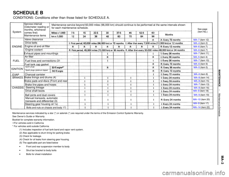
Maintenance services indicated by a star (*) or asterisk (*) are required under the terms of the Emission Control Systems Warranty.
See Owner's Guide or Warranty
Booklet for complete warranty information.
� For vehicles sold in California
* For vehicles sold outside California
(1) Includes inspection of fuel tank band and vapor vent system.
(2) Also applicable to drum lining for parking brake.
(3) Check for leakage.
(4) Check for oil leaks from steering gear housing.
(5) The applicable part are listed below
wFront and rear suspension member to body
wStrut bar bracket to body bolts
wBolts for sheet installation
Maintenance service beyond 60,000 miles (96,000 km) should continue to be performed at the same intervals shown
for each maintenance schedule.
SCHEDULE BCONDITIONS: Conditions other than those listed for SCHEDULE A.
Service interval
(Odometer reading or
months, whichever
comes first)
Maintenance items
Manual transaxle, automatic
transaxle and differential (3) Brake pads and discs (Front and rearBolts and nuts on chassis and body 17)Exhaust pipes and mountings
Steering gear housing oil 1s) Brake linings and drums (4)
Brake line pipes and hoses Fuel lines and connections (31
Ball joints and dust covers Engine oil and oil filterSpark plugs (platinum tippedFuel tank cap gasket
MA±14 (item 22) MA±10 (item 20)
Charcoal canister
Steering linkage
Drive shaft boots
MA±7 (item 11)
MA±9 (item 19) MA±9 (item 18) MA±7 (item 13) MA±7 (item 10)
MA±8 (item 14) MA±7 (item 12)
MA±8 (item 16) MA±8 (item 15) See page
(item No.)
Engine coolant
MA±9 (item 17)
Valve clearance
MA±6 (item 8) MA±4 (item 2)
MA±6 (item 9) MA±6 (item 7)
MA±6 (item 7)
MA±5 (item 5) MA±5 (item 4)
Drive belts
Air filterSpark plugs
IGNITION
CHASSISBRAKES ENGINESystem
EVAPFUEL
± MAINTENANCEMaintenance ScheduleMA±3
Page 1927 of 2389

23. FINAL INSPECTION
(a) Check the operation of the body parts:
wHood
Auxiliary catch operation properly
Hood locks securely when closed
wFront and rear doors
Door locks operate properly
Doors close properly
wLuggage compartment door and back door
Door sock operates properly
wSeats
Seat adjusts easily and locks securely in any position
Front seat back locks securely in any position
Folding±down rear seat backs lock securely
(b) Road test
wCheck the engine and chassis for abnormal noises.
wCheck that the vehicle does not wander or pull to one side.
wCheck that the brakes work properly and do not drag.
wPerform bedding down of the parking brake shoes and drum.
(See page MA±8)
(c) Be sure to deliver a clean car especially check:
wSteering wheel
wShift lever knob
wAll switch knobs
wDoor handles
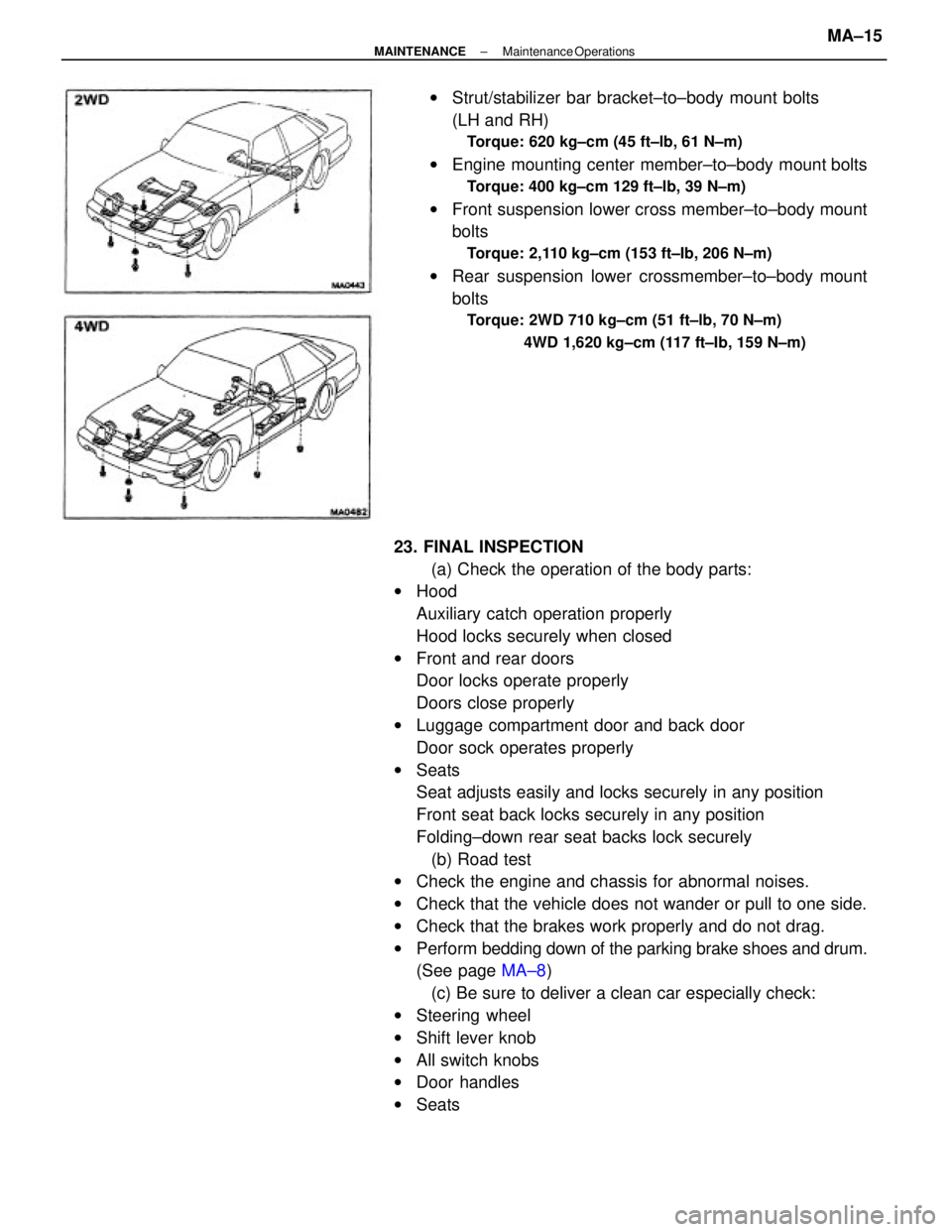
wSeatswStrut/stabilizer bar bracket±to±body mount bolts
(LH and RH)
Torque: 620 kg±cm (45 ft±lb, 61 N±m)
wEngine mounting center member±to±body mount bolts
Torque: 400 kg±cm 129 ft±lb, 39 N±m)
wFront suspension lower cross member±to±body mount
bolts
Torque: 2,110 kg±cm (153 ft±Ib, 206 N±m)
wRear suspension lower crossmember±to±body mount
bolts
Torque: 2WD 710 kg±cm (51 ft±lb, 70 N±m)
4WD 1,620 kg±cm (117 ft±Ib, 159 N±m)
± MAINTENANCEMaintenance OperationsMA±15
Page 2152 of 2389
INSPECTION OF AXLE HUB BEARING
1. ROTATE BRAKE DRUM
Rotate the drum by hand, if the movement is not smooth and
free, replace the axle hub bearing.
2. REMOVE BRAKE DRUM
3. CHECK BEARING PLAY AXIAL DIRECTION
Limit: 0.05 mm (0.0020 in.)
If not within specification, disassembly and inspection the
axle hub assembly.
REMOVAL OF REAR AXLE HUB AND
CARRIER
1. REMOVE BRAKE DRUM
2. DISCONNECT BRAKE TUBE FROM BACKING PLATE
Using SST, disconnect the brake tube from the backing
plate.
SST 09751±36011
3. REMOVE REAR AXLE HUB
(a) Remove the four axle hub and carrier mounting
bolts.
(b) Remove the axle hub and brake assembly.
(c) Remove the O±ring from the backing plate.
4. REMOVE REAR AXLE CARRIER
(a) Disconnect the strut rod from the axle carrier.
(b) Disconnect the No. 1 and No.2 suspension arm from the
axle carrier.
± REAR AXLE AND SUSPENSIONRear Axle Hub and Carrier (FWD)RA±6
Page 2155 of 2389
INSTALLATION OF REAR AXLE HUB
AND CARRIER
(see page RA±5)
1. INSTALL REAR AXLE CARRIER
(a) Place the axle carrier position.
(b) Install and torque the axle carrier mounting bolts and
nuts to the shock absorber.
Toque: 2,300 kg±cm (166 ft±Ib, 226 N±m)
2. INSTALL REAR AXLE HUB
(a) Install the brake assembly and anew oil seal to the axle
carrier. (c) Connect the No. 1 and No.2 suspension arm to
the axle carrier with the bolt, and temporarily
install the retainer and nut.
(d) Temporarily connect the strut rod to the axle carrier
with the bolt and the nut as shown in the figure. (d) Using a hammer and a chisel, stake the nut.
± REAR AXLE AND SUSPENSIONRear Axle Hub and Carrier (FWD)RA±9
Page 2156 of 2389
5. INSTALL WHEELS AND LOWER VEHICLE
(a) Install the wheels.
(b) Remove the stands and bounce the vehicle up and
down to stabilize the suspension.
6. TORQUE AXLE CARRIER MOUNTING BOLTS
Torque the axle carrier mounting blots with the vehicle
weight on the suspension.
Torque:
Strut rod x Axle carrier
1,150 kg±cm (83 ft±Ib, 113 N±m)
No. 1 and No. 2 suspension arm x Axle carrier
1,850 kg±cm (134 ft±Ib, 181 N±m)
7. BLEED BRAKE SYSTEM
(See page BR±7)
8. CHECK REAR WHEEL ALIGNMENT
(See page RA±3) 3. TORQUE BRAKE TUBE
Using SST, torque the brake tube union.
SST 09751±36011
4. INSTALL BRAKE DRUM(b) Temporarily connect the brake tube to the backing
plate.
(c) Install the axle hub and torque the four
bolts.
Torque: 820 kg±cm (59 ft±Ib, 80 N ± m )
± REAR AXLE AND SUSPENSIONRear Axle Hub and Carrier (FWD)RA±10