Page 1387 of 2389
6. REMOVE DRIVE SHAFT (LH drive shaft)
(a) Remove the six bolts and three washers, and remove the
LH drive shaft carefully.
NOTICE: When moving the drive shaft, do not compress the in-
board boot so that the inside bails might be dropped out.
(b) Remove the joint end cover gasket from the drive shaft.
(RH drive shaft)
(a) Drain out the gear oil.
(b) Remove the bearing lock bolt.
(c) Using pliers, remove the snap ring, and pull out
the drive shaft with the center drive shaft. (c) Using a plastic hammer, disconnect the drive
shaft from axle hub.
NOTICE: Cover the drive shaft boot with cloth to pro-
tect it from damage.
(d) Push the front axle hub toward the outside of the
vehicle, and separate the drive shaft from the
axle hub.
HINT: If the drive shaft could not be pulled out,
using a brass bar and a hammer, tap out the drive
shaft.
± FRONT AXLE AND SUSPENSIONFront Drive Shaft (FWD VZV21 )FA±30
Page 1402 of 2389

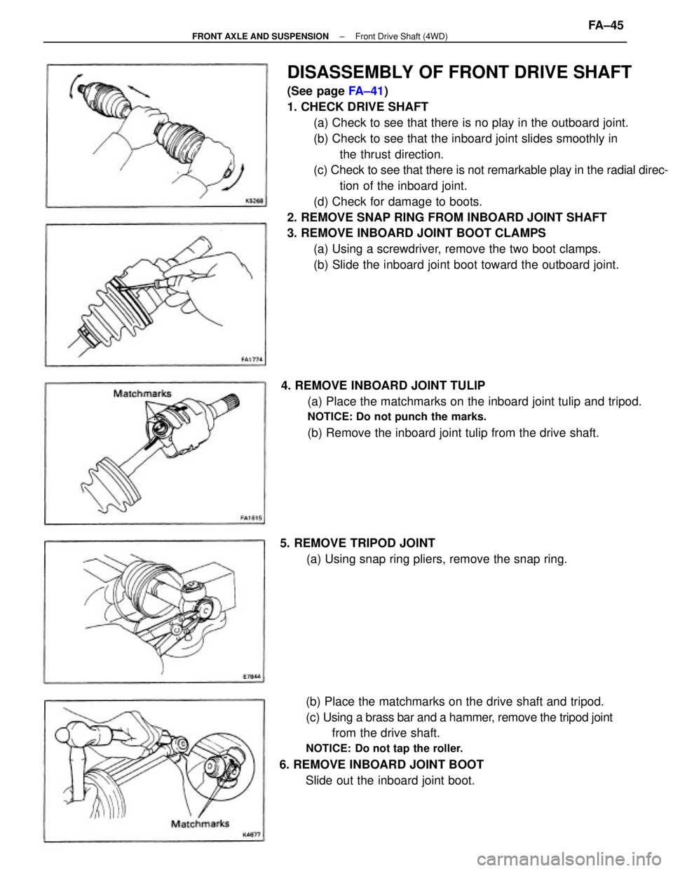
DISASSEMBLY OF FRONT DRIVE SHAFT
(See page FA±41)
1. CHECK DRIVE SHAFT
(a) Check to see that there is no play in the outboard joint.
(b) Check to see that the inboard joint slides smoothly in
the thrust direction.
(c) Check to see that there is not remarkable play in the radial direc-
tion of the inboard joint.
(d) Check for damage to boots.
2. REMOVE SNAP RING FROM INBOARD JOINT SHAFT
3. REMOVE INBOARD JOINT BOOT CLAMPS
(a) Using a screwdriver, remove the two boot clamps.
(b) Slide the inboard joint boot toward the outboard joint.
(b) Place the matchmarks on the drive shaft and tripod.
(c) Using a brass bar and a hammer, remove the tripod joint
from the drive shaft.
NOTICE: Do not tap the roller.
6. REMOVE INBOARD JOINT BOOT
Slide out the inboard joint boot. 4. REMOVE INBOARD JOINT TULIP
(a) Place the matchmarks on the inboard joint tulip and tripod.
NOTICE: Do not punch the marks.
(b) Remove the inboard joint tulip from the drive shaft.
5. REMOVE TRIPOD JOINT
(a) Using snap ring pliers, remove the snap ring.
± FRONT AXLE AND SUSPENSIONFront Drive Shaft (4WD)FA±45
Page 1912 of 2389

Maintenance services indicated by a star (*) or asterisk (*) are required under the terms of the Emission Control Systems Warranty. See Owner's Guide or Warranty Booklet
for complete warranty information.
* For vehicles sold in California
* For vehicles sold outside California
(1) Applicable to vehicles operated under conditions of extensive idling and /or low speed driving for long distances such as police, taxi or door±to±door delivery use.
(2) Applicable when operating mainly on dusty roads. If not, follow SCHEDULE B.
(3) Includes inspection of fuel tank band and vapor vent system.
(4) Also applicable to lining drum for parking brake.
(5) Check for leakage.
(6) Check for oil leaks from steering gear housing.
(7) Applicable only when operating mainly on rough, muddy roads. The applicable parts are listed below. For other usage conditions, refer to SCHEDULE B.
w
Front and rear suspension member to body
w
0 Strut bar bracket to body bolts
w
Bolts for sheet installation
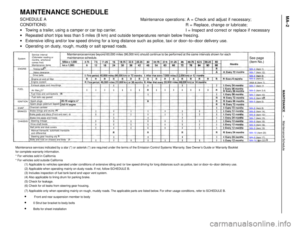
MAINTENANCE SCHEDULESCHEDULE A
CONDITIONS:
wTowing a trailer, using a camper or car top carrier.
wRepeated short trips less than 5 miles (8 km) and outside temperatures remain below freezing.
wExtensive idling and/or low speed driving for a long distance such as police, taxi or door±to±door delivery use.
wOperating on dusty, rough, muddy or salt spread roads.Maintenance operations: A = Check and adjust if necessary;
R = Replace, change or lubricate;
I = Inspect and correct or replace if necessary
Maintenance services beyond 60,000 miles (96,000 km) should continue to be performed at the same intervals shown for each
maintenance schedule.
Service interval
(Odometer reading or
months, whichever
comes first)
Maintenance items
Manual transaxle, automatic transaxle
and differential Brake pads and discs (Front and rear)
Bolts and nuts on chassis and bodyExhaust pipes and mountings
Steering gear housing oily Brake line pipes and hosesFuel lines and connections
Ball joints and dust coversEngine oil and oil filter
Spark plugs (platinum tipped)MA±4 (item 2)
MA±6 (item 6)
Brake linings and drumsFuel tank cap gasket
Drive shaft boots
MA±14 item 221 MA±10 (item 20) MA±5 (item 3,4)
Steering linkageMA±7 (item 12)
MA±8 (item 14) Valve clearance
MA±8 (item 16)
MA±9 (item 19) MA±7 (item 13) MA±7 (item 11
MA±7 (item 10)
MA±9 (item 18) Charcoal canister
MA±9 (item 17) MA±8 (item 151
See page
(item No.)
Engine coolant
MA±6 (item 9) MA±4 (item 1)
MA±4 (item 2)
MA±5 (item 5)
MA±8 (item 8) AAA±6 (item 7)
Air filter¿21*
Spark plugsTiming belt
Drive belts
IGNITION
CHASSIS BRAKESENGINESystem
EVAP FUEL
± MAINTENANCEMaintenance ScheduleMA±2
Page 1933 of 2389
16. DISCONNECT LEFT STEERING KNUCKLE FROM
LOWER ARM
(a) Disconnect the steering knuckle from the tower arm.
(b) Pull the steering knuckle toward the outside and remove
the drive shaft.
17. REMOVE STABILIZER BAR
(See page FA±34) 15. REMOVE CENTER DRIVE SHAFT
(a) Using pliers, remove the snap ring from the bearing
bracket.
(b) Remove the bolt on the bearing bracket.
(c) Pull out the center drive shaft. 13. REMOVE ENGINE MOUNTING CENTER MEMBER
(a) Remove the front and rear engine mounting bolts.
(b) Remove the engine mounting center member.
14. DISCONNECT BOTH DRIVE SHAFTS
Loosen the six nuts while depressing the brake pedal. 12. REMOVE SUSPENSION LOWER CROSSMEMBER
± MANUAL TRANSAXLES51 Transmission.MT±5
Page 2225 of 2389
Engine coolant x Drain plug
Water pump x Water pump cover
Water pump x Cylinder head
Water by±pass pipe X Water pump
Water inlet housing x Water pump
Oil cooler x Radiator tower tank
Cylinder block x Drain plug
Water pump x Cylinder block
Water inlet x Water pump
Water inlet pipe x Alternator belt adjusting bar
LUBRICATION SYSTEM (3S±FE)
SpecificationsTorque Specifi
cations (3S±FE)
COOLING SYSTEM
Specifications
Torque Specifications (2VZ±FE)
Valve opening temperature
Valve lift at 95°C (203°F) Relief valve opening pressure
Engine coolant capacityEngine coolant capacity
at Idling
at 3,040 rpm
STD
Limit
STD
Limit Body clearance .See page A±20 STD
Limit
Part tightened
Part tightenedSee page A±2
Tip clearance3S±FE
2VZ±FE
Oil pressureThermostat
Oil pumpRadiator
± SERVICE SPECIFICATIONSCooling SystemA±17
Page 2229 of 2389
Engine coolant x Drain plug
Water pump x Water pump cover
Water pump x Cylinder head
Water by±pass pipe X Water pump
Water inlet housing x Water pump
Oil cooler x Radiator tower tank
Cylinder block x Drain plug
Water pump x Cylinder block
Water inlet x Water pump
Water inlet pipe x Alternator belt adjusting bar
LUBRICATION SYSTEM (3S±FE)
SpecificationsTorque Specifi
cations (3S±FE)
COOLING SYSTEM
Specifications
Torque Specifications (2VZ±FE)
Valve opening temperature
Valve lift at 95°C (203°F) Relief valve opening pressure
Engine coolant capacityEngine coolant capacity
at Idling
at 3,040 rpm
STD
Limit
STD
Limit Body clearance .See page A±20 STD
Limit
Part tightened
Part tightenedSee page A±2
Tip clearance3S±FE
2VZ±FE
Oil pressureThermostat
Oil pumpRadiator
± SERVICE SPECIFICATIONSLubrication System (3S±FE)A±17