Page 212 of 2389

4. The liquid refrigerant is charged by the expansion valve into a low temperature, low pressure liquid and
geseous mixture.
5. This cold and foggy refrigerant flows to the evaporator. Vaporizing the liquid in the evaporator, the heat
from the warm air stream passing through the evaporator core is transfered to the refrigerant.
All the liquid is changed into geseous refrigerant in the evaporator and only heat±laden geseous refrig-
erant is drawn into the compressor. Then the process is repeated again.
GENERAL DESCRIPTION
REFRIGERATION CYCLE
1. The compressor discharges high temperature and high pres-
sure refrigerant containing the heat absorbed from the
evaporator plus the heat created by the compressor in a dis-
charge stroke.
2. This gaseous refrigerant flows into the condenser. In the con-
denser, the gaseous refrigerant condenses into liquid
refrigerant.
3. This liquid refrigerant flows into the receiver which stores and
filters the liquid refrigerant till the evaporator requires the ref±
rigerant.
± AIR CONDITIONING SYSTEMAIR CONDITIONING SYSTEM General DescriptionAC±13
Page 762 of 2389
2. REMOVE CONTROL LEVER
(a) Remove the bail set plate and the ball.
(b) Remove the control lever with the spring.
3. REMOVE SWITCHES
Remove the switches with the four screws.
4. INSTALL SWITCHES(b) From the open end, insert a miniature screwdriver
between the locking lug and the terminal.
(c) Pry down the locking lug with the screwdriver and
pull the terminal out from the rear.
5. INSTALL CONTROL LEVER
(a) Insert the spring into the control lever and install the
control lever. 1. REMOVE TERMINALS FROM CONNECTOR
(a) Release the four tabs and open the terminal cover.
REPLACEMENT OF SWITCHES
± BODY ELECTRICAL SYSTEMLightingBE±16
Page 975 of 2389

Clutch pedal freeplay excessive
Air in clutch lines
Clutch release cylinder faulty
Clutch master cylinder faulty
Clutch disc out of true, runout is excessive or
lining broken
Splines on input shaft or clutch disc dirty or
burred
Clutch pressure plate faulty
Clutch disc lining oily or worn out
Pressure plate faulty
Clutch diaphragm spring bent
Engine mounts looseClutch pedal freeplay insufficient
Clutch disc lining oily or worn out
Pressure plate faulty
Release fork binding
Inspect clutch disc
Replace clutch cover
Align clutch diaphragm spring
Repair as necessaryAdjust pedal freeplay
Bleed clutch system
Repair release cylinder
Repair master cylinder
Inspect clutch disc
Air in clutch lines
Clutch release cylinder faulty
Clutch master cylinder faultyAdjust pedal freeplay
inspect clutch disc
Replace clutch cover
inspect release fork
Bleed clutch system
Repair release cylinder
Repair master cylinder
Loose part inside housing
Release bearing worn or dirtyRepair as necessary
Replace clutch cover
TROUBLESHOOTING
Repair as necessary
Replace release bearing Hard to shift or will not
shiftCL±3
CL±4
CL±7
CL±5
CL±9
Clutch pedal spongyClutch grabs/
chattersCL±3
CL±9
CL±9
CL±9
CL±9
CL±9
CL±9
CL±4
CL±7
CL±5 Possible cause
Clutch noisy Clutch slipsProblem
RemedyPage
± CLUTCHTroubleshootingCL±2
Page 1020 of 2389

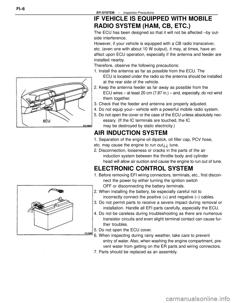
IF VEHICLE IS EQUIPPED WITH MOBILE
RADIO SYSTEM (HAM, CB, ETC.)
The ECU has been designed so that it will not be affected ±by out-
side interference.
However, if your vehicle is equipped with a CB radio transceiver,
etc. (even one with about 10 W output), it may, at times, have an
affect upon ECU operation, especially if the antenna and feeder are
installed nearby.
Therefore, observe the following precautions:
1. Install the antenna as far as possible from the ECU. The
ECU is located under the radio so the antenna should be installed
at the rear side of the vehicle.
2. Keep the antenna feeder as far away as possible from the
ECU wires ± at least 20 cm (7.87 in.) ± and, especially, do not wind
them together.
3. Check that the feeder and antenna are properly adjusted.
4. Do not equip your± vehicle with a powerful mobile radio system.
5. Do not open the cover or the case of the ECU unless absolutely nec-
essary. (If the IC terminals are touched, the IC
may be destroyed by static electricity.)
AIR INDUCTION SYSTEM
1. Separation of the engine oil dipstick, oil filler cap, PCV hose,
etc. may cause the engine to run out¿¿ tune.
2. Disconnection, looseness or cracks in the parts of the air
induction system between the throttle body and cylinder
head will allow air suction and cause the engine to run out of tune.
ELECTRONIC CONTROL SYSTEM
1. Before removing EFI wiring connectors, terminals, etc., first discon-
nect the power by either turning the ignition switch
OFF or disconnecting the battery terminals.
2. When installing the battery, be especially careful not to
incorrectly connect the positive (+) and negative (±) cables.
3. Do not permit parts to receive a severe impact during removal or
installation. Handle all EFI parts carefully, especially the ECU.
4. Do not be careless during troubleshooting as there are numerous
transistor circuits and even slight terminal contact can cause fur-
ther troubles.
5. Do not open the ECU cover.
6. When inspecting during rainy weather, take care to prevent
entry of water. Also, when washing the engine compartment, pre-
vent water from getting on the ER parts and wiring connectors.
7. Parts should be replaced as an assembly.
± EFI SYSTEMInspection PrecautionsFI±6
Page 1157 of 2389

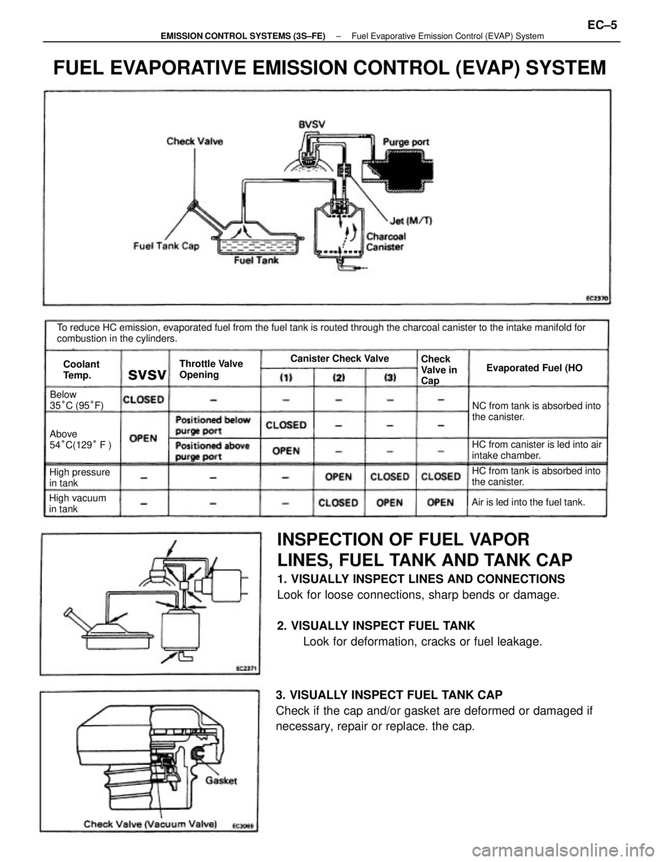
INSPECTION OF FUEL VAPOR
LINES, FUEL TANK AND TANK CAP
1. VISUALLY INSPECT LINES AND CONNECTIONS
Look for loose connections, sharp bends or damage.
2. VISUALLY INSPECT FUEL TANK
Look for deformation, cracks or fuel leakage.
3. VISUALLY INSPECT FUEL TANK CAP
Check if the cap and/or gasket are deformed or damaged if
necessary, repair or replace. the cap.
To reduce HC emission, evaporated fuel from the fuel tank is routed through the charcoal canister to the intake manifold for
combustion in the cylinders.
FUEL EVAPORATIVE EMISSION CONTROL (EVAP) SYSTEM
HC from canister is led into air
intake chamber.NC from tank is absorbed into
the canister.
HC from tank is absorbed into
the canister.
Air is led into the fuel tank. Throttle Valve
OpeningEvaporated Fuel (HO
High pressure
in tankAbove
54°C(129° F )
High vacuum
in tankBelow
35°C (95°F)Canister Check Valve
Check
Valve in
Cap Coolant
Temp.
svsv
± EMISSION CONTROL SYSTEMS (3S±FE)Fuel Evaporative Emission Control (EVAP) SystemEC±5
Page 1169 of 2389
INSPECTION OF FUEL VAPOR LINES,
FUEL
TANK AND TANK CAP
1. VISUALLY INSPECT LINES AND CONNECTIONS
Look for loose connections, sharp bends or damage.
2. VISUALLY INSPECT FUEL TANK
Look for deformation, cracks or fuel leakage.
To reduce HC emissions, evaporated fuel from the fuel tank is routed through the charcoal canister to the intake manifold for
combustion in the cylinders.
3. VISUALLY INSPECT FUEL TANK CAP
Check if the cap and/or gasket are deformed or damaged.
If necessary, repair or replace the cap.
FUEL EVAPORATIVE EMISSION CONTROL (EVAP) SYSTEM
HC from canister is led into air
intake chamber. HC from tank is absorbed into
the canister.
HC from tank is absorbed
into the canister. Positioned below
purge port
Positioned above
purge port
Air is led into the fuel tank. Throttle Valve
OpeningEvaporated Fuel (HC) Canister Check Valve
Check
Valve in
Cap
Coolant
Te m p .BVSV
± EMISSION CONTROL SYSTEMS (2VZ±FE)Emission Control (EVAP) SystemEC±17
Page 1359 of 2389

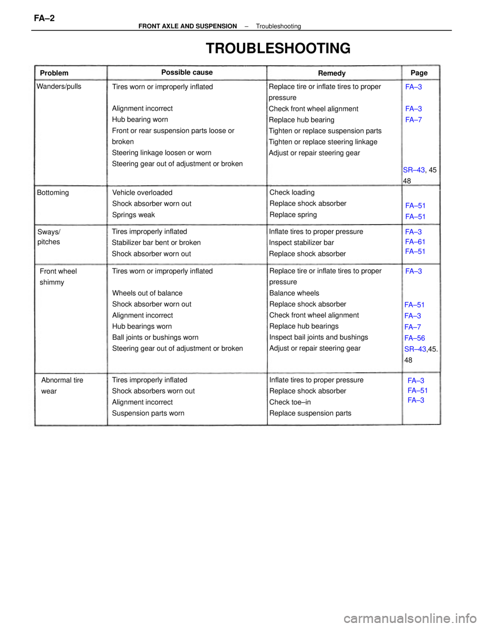
Replace tire or inflate tires to proper
pressure
Check front wheel alignment
Replace hub bearing
Tighten or replace suspension parts
Tighten or replace steering linkage
Adjust or repair steering gear
Replace tire or inflate tires to proper
pressure
Balance wheels
Replace shock absorber
Check front wheel alignment
Replace hub bearings
Inspect bail joints and bushings
Adjust or repair steering gear Wheels out of balance
Shock absorber worn out
Alignment incorrect
Hub bearings worn
Ball joints or bushings worn
Steering gear out of adjustment or broken Alignment incorrect
Hub bearing worn
Front or rear suspension parts loose or
broken
Steering linkage loosen or worn
Steering gear out of adjustment or broken
Inflate tires to proper pressure
Replace shock absorber
Check toe±in
Replace suspension parts Tires improperly inflated
Shock absorbers worn out
Alignment incorrect
Suspension parts wornInflate tires to proper pressure
Inspect stabilizer bar
Replace shock absorber Tires improperly inflated
Stabilizer bar bent or broken
Shock absorber worn outVehicle overloaded
Shock absorber worn out
Springs weakCheck loading
Replace shock absorber
Replace spring
FA±51
FA±3
FA±7
FA±56
SR±43,45.
48
TROUBLESHOOTING
Tires worn or improperly inflatedTires worn or improperly inflated
Abnormal tire
wear Front wheel
shimmyFA±3
FA±61
FA±51
FA±3
FA±51
FA±3 SR±43, 45
48 Possible cause
Sways/
pitches Wanders/pulls
FA±51
FA±51 BottomingFA±3
FA±7 Problem
RemedyPage
FA±3
FA±3
± FRONT AXLE AND SUSPENSIONTroubleshootingFA ± 2
Page 1360 of 2389

FRONT WHEEL ALIGNMENT
1. MAKE FOLLOWING CHECKS AND CORRECT ANY
PROBLEMS
(a) Check the tires for wear, size and proper inflation.
Cold tire inflation pressure:
FWD/SV21 and 4WD 2.1 kg±cm2 (30 psi, 206 kPa)
FWD/VZV21 2.2 kg±cm2 (31 psi, 216 kPa)
(b) Check the front wheel bearings for looseness.
(c) Check the wheel runout.
Lateral runout: Less than 1.0 mm (0.039 in.)
(d) Check the front suspension for looseness.
(e) Check the steering linkage for looseness.
(f) Check that the front shock absorber function properly
by using the standard bounce test.
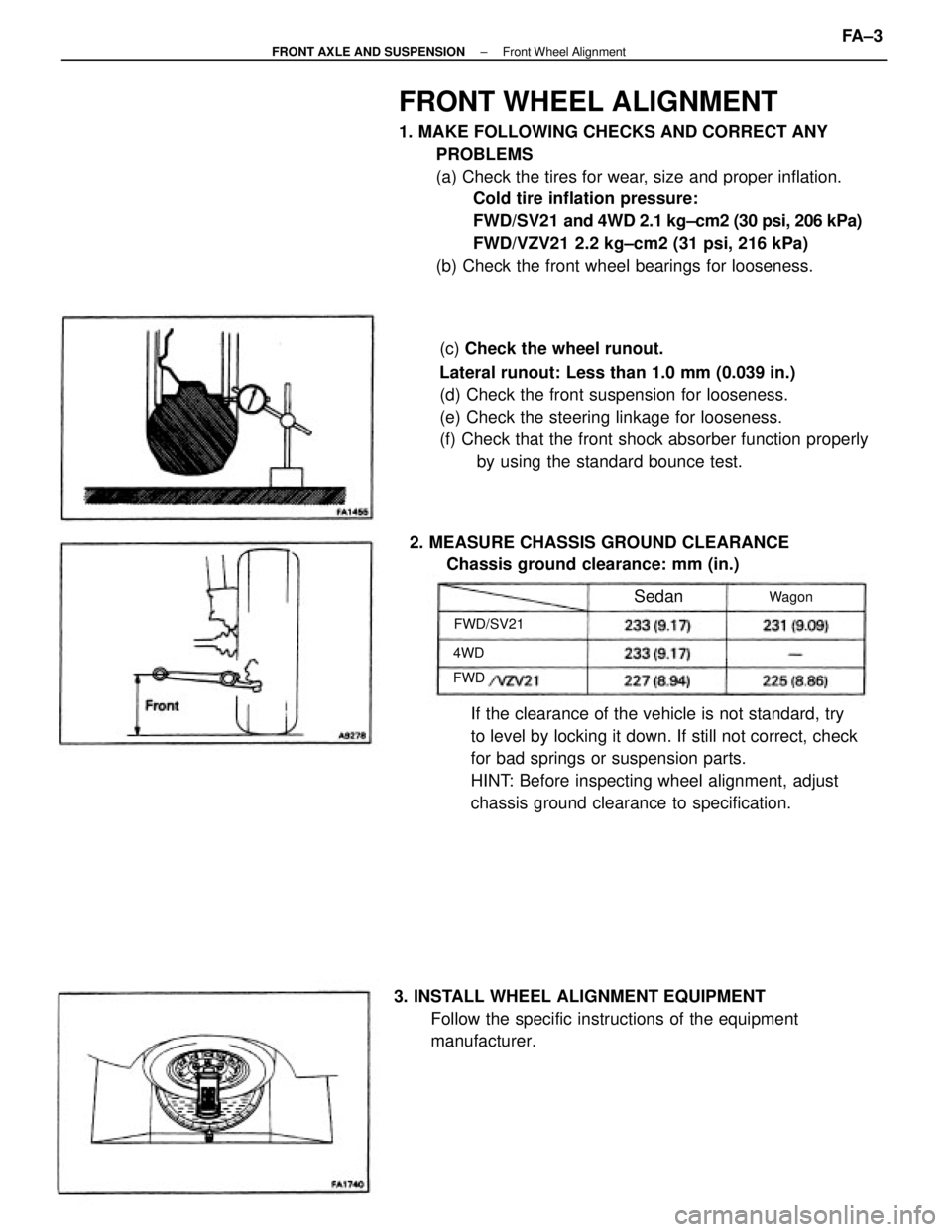
If the clearance of the vehicle is not standard, try
to level by locking it down. If still not correct, check
for bad springs or suspension parts.
HINT: Before inspecting wheel alignment, adjust
chassis ground clearance to specification.
3. INSTALL WHEEL ALIGNMENT EQUIPMENT
Follow the specific instructions of the equipment
manufacturer. 2. MEASURE CHASSIS GROUND CLEARANCE
Chassis ground clearance: mm (in.)
FWD/SV21Wagon
Sedan
4WD
FWD
± FRONT AXLE AND SUSPENSIONFront Wheel AlignmentFA ± 3