Page 234 of 2389

RECEIVER
(See page AC±12)
ON±VEHICLE INSPECTION
CHECK SIGHT GLASS, FUSIBLE PLUG AND FITTINGS FOR
LEAKAGE
Use a gas leak tester. Repair as necessary.
REMOVAL OF RECEIVER
1. DISCHARGE REFRIGERATION SYSTEM
2. REMOVE BATTERY, RESERVE TANK AND IGNITOR
BRACKET
3. DISCONNECT TWO LIQUID TUBES FROM RECEIVER
HINT: Cap the open fittings immediately to keep moisture out of
the system.
4. REMOVE RECEIVER FROM RECEIVER HOLDER
INSTALLATION OF RECEIVER
1. INSTALL RECEIVER IN RECEIVER HOLDER
HINT: Do not remove the blind plugs until ready for connection.
2. CONNECT TWO LIQUID TUBES TO RECEIVER
Torque: 55 kg±cm (48 in.±Ib, 5.4 N±m)
3. REINSTALL IGNITOR BRACKET, RESERVE TANK AND
BATTERY
4. IF RECEIVER WAS REPLACED, ADD COMPRESSOR
OIL TO COMPRESSOR
Add 20 cc (0.7 fl.oz.)
Compressor oil: DENSOOIL 6,
SUNISO NO. 5GS or equivalent
5. EVACUATE AIR FROM AIR CONDITIONING SYSTEM
6. CHARGE AND CONDITIONING SYSTEM WITH
REFRIGERANT AND CHECK FOR GAS LEAKAGE
Specified amount: 600 ± 750 g (1.3 ± 1.7 Ib)
± AIR CONDITIONING SYSTEMReceiverAC±32
Page 1157 of 2389

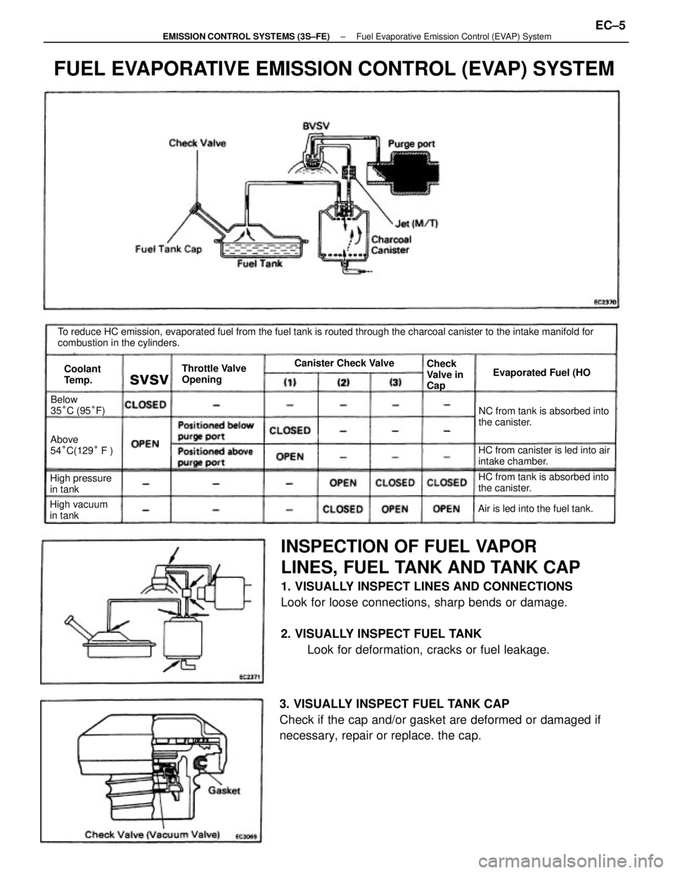
INSPECTION OF FUEL VAPOR
LINES, FUEL TANK AND TANK CAP
1. VISUALLY INSPECT LINES AND CONNECTIONS
Look for loose connections, sharp bends or damage.
2. VISUALLY INSPECT FUEL TANK
Look for deformation, cracks or fuel leakage.
3. VISUALLY INSPECT FUEL TANK CAP
Check if the cap and/or gasket are deformed or damaged if
necessary, repair or replace. the cap.
To reduce HC emission, evaporated fuel from the fuel tank is routed through the charcoal canister to the intake manifold for
combustion in the cylinders.
FUEL EVAPORATIVE EMISSION CONTROL (EVAP) SYSTEM
HC from canister is led into air
intake chamber.NC from tank is absorbed into
the canister.
HC from tank is absorbed into
the canister.
Air is led into the fuel tank. Throttle Valve
OpeningEvaporated Fuel (HO
High pressure
in tankAbove
54°C(129° F )
High vacuum
in tankBelow
35°C (95°F)Canister Check Valve
Check
Valve in
Cap Coolant
Temp.
svsv
± EMISSION CONTROL SYSTEMS (3S±FE)Fuel Evaporative Emission Control (EVAP) SystemEC±5
Page 1169 of 2389
INSPECTION OF FUEL VAPOR LINES,
FUEL
TANK AND TANK CAP
1. VISUALLY INSPECT LINES AND CONNECTIONS
Look for loose connections, sharp bends or damage.
2. VISUALLY INSPECT FUEL TANK
Look for deformation, cracks or fuel leakage.
To reduce HC emissions, evaporated fuel from the fuel tank is routed through the charcoal canister to the intake manifold for
combustion in the cylinders.
3. VISUALLY INSPECT FUEL TANK CAP
Check if the cap and/or gasket are deformed or damaged.
If necessary, repair or replace the cap.
FUEL EVAPORATIVE EMISSION CONTROL (EVAP) SYSTEM
HC from canister is led into air
intake chamber. HC from tank is absorbed into
the canister.
HC from tank is absorbed
into the canister. Positioned below
purge port
Positioned above
purge port
Air is led into the fuel tank. Throttle Valve
OpeningEvaporated Fuel (HC) Canister Check Valve
Check
Valve in
Cap
Coolant
Te m p .BVSV
± EMISSION CONTROL SYSTEMS (2VZ±FE)Emission Control (EVAP) SystemEC±17
Page 1287 of 2389

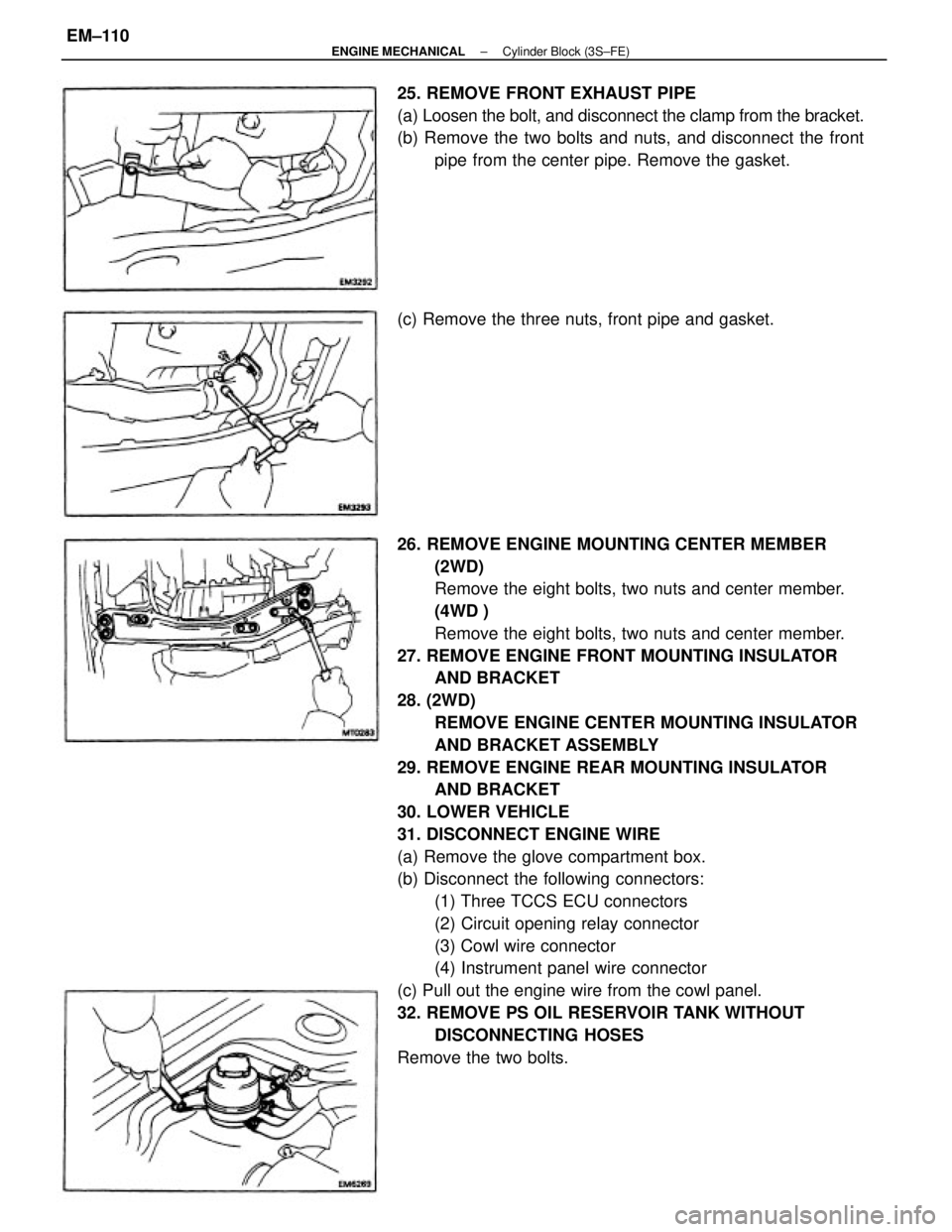
26. REMOVE ENGINE MOUNTING CENTER MEMBER
(2WD)
Remove the eight bolts, two nuts and center member.
(4WD )
Remove the eight bolts, two nuts and center member.
27. REMOVE ENGINE FRONT MOUNTING INSULATOR
AND BRACKET
28. (2WD)
REMOVE ENGINE CENTER MOUNTING INSULATOR
AND BRACKET ASSEMBLY
29. REMOVE ENGINE REAR MOUNTING INSULATOR
AND BRACKET
30. LOWER VEHICLE
31. DISCONNECT ENGINE WIRE
(a) Remove the glove compartment box.
(b) Disconnect the following connectors:
(1) Three TCCS ECU connectors
(2) Circuit opening relay connector
(3) Cowl wire connector
(4) Instrument panel wire connector
(c) Pull out the engine wire from the cowl panel.
32. REMOVE PS OIL RESERVOIR TANK WITHOUT
DISCONNECTING HOSES
Remove the two bolts. 25. REMOVE FRONT EXHAUST PIPE
(a) Loosen the bolt, and disconnect the clamp from the bracket.
(b) Remove the two bolts and nuts, and disconnect the front
pipe from the center pipe. Remove the gasket.
(c) Remove the three nuts, front pipe and gasket.
± ENGINE MECHANICALCylinder Block (3S±FE)EM±110