1986 TOYOTA CAMRY V20 instrument panel
[x] Cancel search: instrument panelPage 289 of 2389

INSPECTION ELECTRONIC CONTROL
COMPONENTS
1. INSPECT VOLTAGE OF ECT ECU CONNECTOR
(a) Remove the glove box and instrument panel.
(b) Turn on the ignition switch.
(e) Measure the voltage at each terminal.
Throttle valve fully closed to fully open Throttle valve fully closed to fully open
Throttle valve fully closed to fully open
Vehicle moving (Cruise control OFF)Standing still (Cruise control OFF) Throttle valve opening above 1 .5°
When brake pedal is not depressed When brake pedal is depressed Throttle valve fully closed Throttle valve fully closed
Throttle valve fully closed
Throttle valve fully closed Throttle valve fully open Throttle valve fully open Throttle valve fully openMeasuring condition
Except L range
Except N range Except 2 rangeVoltage (V)
Terminal
N range 2 range
L range
± AUTOMATIC TRANSAXLETroubleshooting (Electronic Control System) (A140E)AT±32
Page 736 of 2389

21. REMOVE NO.1 HEATER REGISTER DUCT
Pry out the clip and remove the duct.
22. REMOVE NO.3 HEATER REGISTER DUCT
Remove the three screws and duct.
23. REMOVE DEFROSTER NOZZLE
Remove the five screws and nozzle.
24. REMOVE NO.1 INSTRUMENT PANEL REGISTER
Remove the two screws and register.
25. REMOVE NO.3 INSTRUMENT PANEL REGISTER
Remove the three screws and register.
26. REMOVE NO.2 INSTRUMENT PANEL REGISTER
Remove the screws and register.
27. REMOVE SAFETY PAD GARNISH
INSTALLATION OF SAFETY PAD
(See pages BO±62, 63)
INSTALL SAFETY PAD PARTS FOLLOWING REMOVAL
SEQUENCE IN REVERSE
HINT:
wWhen reinstall the speedometer cable, first pull on
the cable guide casing.
wInsert the flange of def±nozzle between the rib (A)
and the safety pad.
± BODYSafety PadBO±70
Page 857 of 2389

CHECKS AND ADJUSTMENTS
CHECK AND ADJUSTMENT OF BRAKE
PEDAL
1. CHECK THAT PEDAL HEIGHT IS CORRECT
Pedal height from asphalt sheet:
177.5 ± 187.5 mm (6.988 ± 7.382 in.)
If incorrect, adjust the pedal height.
2. IF NECESSARY, ADJUST PEDAL HEIGHT
(a) If necessary, remove the instrument lower finish pan-
el and air duct.
(b) Loosen the stop light switch lock nut.
(e) Sufficiently loosen the stop light switch.
(d) Loosen the push rod lock nut.
(e) Adjust the pedal height by turning the pedal push
rod.
(f) Return the stop light switch until it lightly contacts the
pedal stopper.
(g) Tighten the two lock nuts.
(h) Check that the stop lights light when the brake pedal
depressed.
(i) After adjusting the pedal height, check and adjust
the pedal freeplay.
3. CHECK THAT PEDAL FREEPLAY IS CORRECT
(a) Stop the engine and depress the brake pedal sever-
al times until there is no more vacuum left in the
booster.
(b) Push in the pedal until the beginning of resistance
is felt. Measure the distance, as shown.
Pedal freeplay: 3 ±6 mm (0.12 ± 0.24 in.)
HINT: The freeplay to the first resistance is due to the play
between the clevis and pin. And it is 1 3 mm (0.04±
0.12 in.) on the pedal.
4. IF NECESSARY, ADJUST PEDAL FREEPLAY
(a) If incorrect, adjust the pedal freeplay by turning the
pedal push rod.
(b) Start the engine and confirm that pedal freepiay ex-
ists.
(e) After adjusting the pedal freeplay, check the pedal
height.
(d) Install the air duct and instrument lower finish panel.
± BRAKE SYSTEMChecks and AdjustmentsBR±6
Page 867 of 2389

INSTALLATION OF BRAKE BOOSTER
(See page BR±15)
1. ADJUST LENGTH OF BOOSTER PUSH ROD
(a) Set the SST on the master cylinder with the gasket,
and then lower the pin until its slightly touches the
piston.
SST 09737±00010
3. CONNECT CLEVIS TO BRAKE PEDAL
Insert the clevis pin into the clevis and brake pedal, and
install the clip to the clevis pin.
4. INSTALL PEDAL RETURN SPRING
5. INSTALL INSTRUMENT LOWER FINISH PANEL(b) Turn the SST upside down and set it on the booster.
SST 49737±00010
(c) Measure the clearance between the booster push
rod and pin head (SST).
Clearance: 0 mm (0 in.)
2. INSTALL BRAKE BOOSTER, GASKET AND CLEVIS
(a) Install the clevis lock nut and clevis to the brake
booster.
(b) Install the brake booster and gasket.
(c) Install and torque the booster mounting nuts.
Torque: 130 kg±cm (9 ft±Ib, 13 N¿ m)
(d) Adjust the booster push rod length until the push rod
lightly touches the pin head.
± BRAKE SYSTEMBrake BoosterBR±16
Page 976 of 2389

CHECK AND ADJUSTMENT OF
CLUTCH PEDAL
1. CHECK THAT PEDAL HEIGHT IS CORRECT
Pedal height from asphalt shaft 181 ± 191 mm
(7:13 ± 7.52 in.)
2. IF NECESSARY, ADJUST PEDAL HEIGHT
(a) Remove the instrument lower finish panel and discon-
nect the air duct.
(b) Loosen the lock nut and turn the stopper bolt (w/o
Cruise control system) or clutch switch (w/ Cruise
control system) until the height is correct. Tighten the
lock nut.
HINT: Before rotating the clutch switch for pedal height
adjustment, disconnect the clutch switch connector.
3. CHECK THAT PEDAL FREEPLAY AND PUSH ROD
PLAY ARE CORRECT
(Pedal Freeplay)
Push in the pedal until the beginning of clutch resistance
is felt.
Pedal freeplay: 5 ± 15 mm (0.20 ± 0.59 in.)
Push rod play at pedal top: 1.0 ± 5.0 mm
(0.039 ± 0.197 in.)
4. IF NECESSARY, ADJUST PEDAL FREEPLAY AND
PUSH ROD PLAY
(a) Loosen the lock nut and turn the push rod until the free-
play and push rod play are correct.
(b) Tighten the lock nut.
(e) After adjusting the pedal freeplay, check the pedal
height.
(d) Connect the air duct and install the lower finish panel.
5. INSPECT CLUTCH RELEASE POINT
(a) Pull the parking brake lever and install wheel stopper.
(b) Start the engine and idle the engine.
(e) Without depressing the clutch pedal, slowly shift the
shift lever into reverse position until the gears contact.
(d) Gradually depress the clutch pedal and measure the
stroke distance from the point the gear noise stops
(release point) up to the full stroke end position.
Standard distance: 25 mm (0.98 in.) or more
(From pedal stroke end position to release point)
If the distance is not as specified, perform the following
operation.
wInspect pedal height.
wInspect push rod play and pedal free play.
wBleed the clutch line.
wInspect the clutch cover and disc.
± CLUTCHCheck and Adjustment of Clutch PedalCL±3
Page 979 of 2389

REMOVAL OF MASTER CYLINDER
1. DRAW OUT FLUID WITH SYRINGE
2. DISCONNECT CLUTCH LINE TUBE
3. REMOVE INSTRUMENT LOWER FINISH PANEL
Remove the lower instrument lower finish panel and disconnect
the air duct from the instrument lower finish panel.
4. REMOVE CLEVIS PIN AND CLIP WITH SPRING
WASHER
Remove the clip and clevis pin with the spring washer.
5. REMOVE MOUNTING NUTS AND PULL OUT MASTER
CYLINDER
DISASSEMBLY OF MASTER CYLINDER
1. REMOVE RESERVOIR TANK
2. REMOVE PUSH ROD AND PISTON
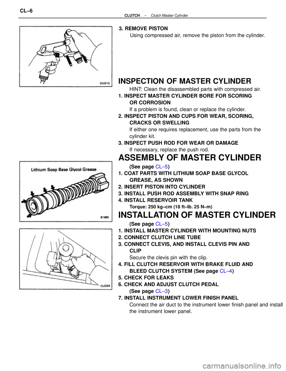
(a) Pull back the boot and, using snap ring pliers, remove the snap
ring.
(b) Pull out the push rod.
CLUTCH MASTER CYLINDER
COMPONENTS
± CLUTCHClutch Master CylinderCL±5
Page 980 of 2389

INSPECTION OF MASTER CYLINDER
HINT: Clean the disassembled parts with compressed air.
1. INSPECT MASTER CYLINDER BORE FOR SCORING
OR CORROSION
If a problem is found, clean or replace the cylinder.
2. INSPECT PISTON AND CUPS FOR WEAR, SCORING,
CRACKS OR SWELLING
If either one requires replacement, use the parts from the
cylinder kit.
3. INSPECT PUSH ROD FOR WEAR OR DAMAGE
If necessary, replace the push rod.
ASSEMBLY OF MASTER CYLINDER
(See page CL±5)
1. COAT PARTS WITH LITHIUM SOAP BASE GLYCOL
GREASE, AS SHOWN
2. INSERT PISTON INTO CYLINDER
3. INSTALL PUSH ROD ASSEMBLY WITH SNAP RING
4. INSTALL RESERVOIR TANK
Torque: 250 kg±cm (18 ft±Ib. 25 N±m)
INSTALLATION OF MASTER CYLINDER
(See page CL±5)
1. INSTALL MASTER CYLINDER WITH MOUNTING NUTS
2. CONNECT CLUTCH LINE TUBE
3. CONNECT CLEVIS, AND INSTALL CLEVIS PIN AND
CLIP
Secure the clevis pin with the clip.
4. FILL CLUTCH RESERVOIR WITH BRAKE FLUID AND
BLEED CLUTCH SYSTEM (See page CL±4)
5. CHECK FOR LEAKS
6. CHECK AND ADJUST CLUTCH PEDAL
(See page CL±3)
7. INSTALL INSTRUMENT LOWER FINISH PANEL
Connect the air duct to the instrument lower finish panel and install
the instrument lower panel. 3. REMOVE PISTON
Using compressed air, remove the piston from the cylinder.
± CLUTCHClutch Master CylinderCL±6
Page 1017 of 2389

The ER system is composed of there basic sub±systems: Fuel, Air Induction and Electronic Control Systems.
FUEL SYSTEM
Fuel is supplied under constant pressure to the EFI injectors by an electric fuel pump. The injectors inject a
metered quantity of fuel into the intake manifold in a accordance with signals from the ECU (Electronic Control
Unit).
AIR INDUCTION SYSTEM
The air induction system provides sufficient air for engine operation.
ELECTRONIC CONTROL SYSTEM
The Camry 3S±FE and 2V1±FE engines are equipped with a Toyota Computer Control System (TCCS) which
centrally controls the EFI, ESA, ISC, Diagnosis systems etc. by means of an Electronic Control Unit (ECU±
formerly ER computer) employing a microcomputer.
By means of the ECU, the TCCS controls the following functions:
1. Electronic Fuel Injection (EFI)
The ECU receives signals from various sensors indicating changing engine operation conditions such as:
Intake air volume
Intake air temperature
Coolant temperature
Engine rpm
Acceleration/deceleration
Exhaust oxygen content etc.
The signals are utilized by the ECU to determine the injection duration necessary for an optimum air±fuel ratio.
2. Electronic Spark Advance (ESA)
The ECU is programmed with data for optimum ignition timing under any and all operating conditions.
Using data provided by sensors which monitor various engine functions (rpm, coolant temperature, etc.), the
microcomputer (ECU) triggers the spark at precisely the right instant. (See IG section)
3. Idle Speed Control (ISC)
The ECU is programmed with target idling speed values to respond to different engine conditions (coolant
temperature, air conditioner ON/OFF, etc.). Sensors transmit signals to the ECU which control the flow of air
through the by±pass of the throttle valve and adjust idle speed to the target value. (See page FI±45,115
or 62, 117)
4. Diagnosis
The ECU detects any malfunctions or abnormalities in the sensor network and lights a ºCHECKº engine warn-
ing light on the instrument panel. At the same time, the trouble is identified and a diagnosis code is recorded
by the ECU. The diagnosis code can be read by the number of blinks of the ºCHECKº engine warning light
when terminals TE1 and E1 are connected. The diagnostic codes are refer to the later page.
(See page FI±25 or 27)
5. Fail±safe Function
In the event of the sensor malfunctioning, a back±up circuit will take over to provide minimal drivability, and
the ºCHECKº engine warning light.
± EFI SYSTEMSystem DescriptionFI±4