Page 217 of 2389

Discharging of Refrigeration System
Evacuating and Charging of
Refrigeration System
(See Air Conditioning Fundamentals and Repairs Pub. No.
36950E)
Condenser clogged
Drive belt slipping
Magnetic clutch faulty
Compressor faulty
Expansion valve faulty
Thermistor faulty
A/C amplifier faulty
Insufficient or too much refrigerant
Air or excessive compressor oil in
system
Receiver clogged
Water valve cable set faultyCheck condenser .
Check or replace drive belt
Check magnetic clutch
Check compressor
Check expansion valve
Check thermistor
Check amplifier
Check refrigerant volume
Evacuate and charge system
Evaporator clogged or frosted
Air leakage from cooling unit or air duct
Air inlet blocked
Blower motor faulty
A/C amplifier faulty
Drive belt slipping
Revolution detecting sensor faulty
(w/Power steering)
A/C amplifier faultyAC±33
AC±21
AC±23
AC±23
AC±39
AC±43
AC±45 to 47
AC±22
Repair as necessary
Replace blower motor
Check amplifierClean evaporator fins or filters
Repair as necessary
Check or replace drive belt
Check sensor
Check receiver
Reset water valve cable
A/C switch
indicator
flashingInsufficient
velocity of cool
airAC±41
AC±39 to 42 Insufficient
cooling
Check amplifier Possible cause
AC±21
AC±24AC±32
BE±79
AC±39 to 42
AC±45 to 47
AC±45 to 47 Remedy ProblemPage
± AIR CONDITIONING SYSTEMTroubleshooting Refrigeration SystemAC±17
Page 1915 of 2389

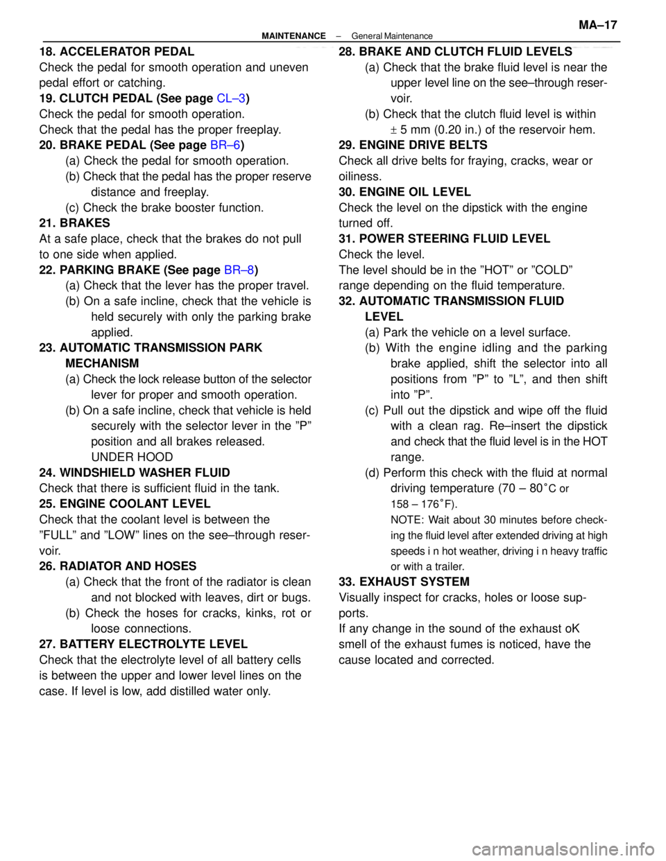
18. ACCELERATOR PEDAL
Check the pedal for smooth operation and uneven
pedal effort or catching.
19. CLUTCH PEDAL (See page CL±3)
Check the pedal for smooth operation.
Check that the pedal has the proper freeplay.
20. BRAKE PEDAL (See page BR±6)
(a) Check the pedal for smooth operation.
(b) Check that the pedal has the proper reserve
distance and freeplay.
(c) Check the brake booster function.
21. BRAKES
At a safe place, check that the brakes do not pull
to one side when applied.
22. PARKING BRAKE (See page BR±8)
(a) Check that the lever has the proper travel.
(b) On a safe incline, check that the vehicle is
held securely with only the parking brake
applied.
23. AUTOMATIC TRANSMISSION PARK
MECHANISM
(a) Check the lock release button of the selector
lever for proper and smooth operation.
(b) On a safe incline, check that vehicle is held
securely with the selector lever in the ºPº
position and all brakes released.
UNDER HOOD
24. WINDSHIELD WASHER FLUID
Check that there is sufficient fluid in the tank.
25. ENGINE COOLANT LEVEL
Check that the coolant level is between the
ºFULLº and ºLOWº lines on the see±through reser-
voir.
26. RADIATOR AND HOSES
(a) Check that the front of the radiator is clean
and not blocked with leaves, dirt or bugs.
(b) Check the hoses for cracks, kinks, rot or
loose connections.
27. BATTERY ELECTROLYTE LEVEL
Check that the electrolyte level of all battery cells
is between the upper and lower level lines on the
case. If level is low, add distilled water only.28. BRAKE AND CLUTCH FLUID LEVELS
(a) Check that the brake fluid level is near the
upper level line on the see±through reser-
voir.
(b) Check that the clutch fluid level is within
+ 5 mm (0.20 in.) of the reservoir hem.
29. ENGINE DRIVE BELTS
Check all drive belts for fraying, cracks, wear or
oiliness.
30. ENGINE OIL LEVEL
Check the level on the dipstick with the engine
turned off.
31. POWER STEERING FLUID LEVEL
Check the level.
The level should be in the ºHOTº or ºCOLDº
range depending on the fluid temperature.
32. AUTOMATIC TRANSMISSION FLUID
LEVEL
(a) Park the vehicle on a level surface.
(b) With the engine idling and the parking
brake applied, shift the selector into all
positions from ºPº to ºLº, and then shift
into ºPº.
(c) Pull out the dipstick and wipe off the fluid
with a clean rag. Re±insert the dipstick
and check that the fluid level is in the HOT
range.
(d) Perform this check with the fluid at normal
driving temperature (70 ± 80
°C or
158 ± 176°F).
NOTE: Wait about 30 minutes before check-
ing the fluid level after extended driving at high
speeds i n hot weather, driving i n heavy traffic
or with a trailer.
33. EXHAUST SYSTEM
Visually inspect for cracks, holes or loose sup-
ports.
If any change in the sound of the exhaust oK
smell of the exhaust fumes is noticed, have the
cause located and corrected.
± MAINTENANCEGeneral MaintenanceMA±17
Page 2276 of 2389
PS pump rotating torque
Steering rack runout
Control valve bearing preload
STEERING
Specifications
Steering effort
Rotor shaft bushing oil clearanceSteering wheel freeplay
Collar No. 1 outer diameter
Vane plate length Rotor and cam ring markMaximum rise of oil level
Oil pressure at idle speed
Vane plate to rotor groove clearance
Flow control valve spring lengthCollar No. 2 outer diameter
Support shim thickness
Drive belt tension Steering
column
Power steering
Total preloadVane plate
± SERVICE SPECIFICATIONSSteeringA±38
Page 2277 of 2389

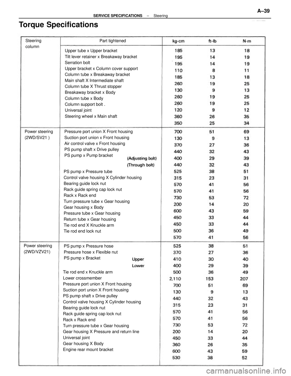
Tie rod end x Knuckle arm
Lower crossmember
Pressure port union X Front housing
Suction port union X Front housing
PS pump shaft x Drive pulley
Control valve housing X Cylinder housing
Bearing guide lock nut
Rack guide spring cap lock nut
Rack x Rack end
Turn pressure tube x Gear housing
Gear housing X Pressure and return line
Universal joint
Gear housing X Body
Engine rear mount bracketUpper tube x Upper bracket
Tilt lever retainer x Breakaway bracket
Serration bolt
Upper bracket x Column cover support
Column tube x Breakaway bracket
Main shaft X Intermediate shaft
Column tube X Thrust stopper
Breakaway bracket x Body
Column tube x Body
Column support bolt .
Universal joint
Steering wheel x Main shaft
PS pump x Pressure tube
Control valve housing X Cylinder housing
Bearing guide lock nut
Rack guide spring cap lock nut
Rack x Rack end
Turn pressure tube x Gear housing
Gear housing x Body
Pressure tube x Gear housing
Return tube x Gear housing
Tie rod end X Knuckle arm
Tie rod end lock nutPressure port union X Front housing
Suction port union x Front housing
Air control valve x Front housing
PS pump shaft x Drive pulley
PS pump x Pump bracket
PS pump x Pressure hose
Pressure hose x Flexible nut
PS pump x Bracket
Torque Specifications
Power steering
(2WD/SV21 )
Power steering
(2WD/VZV21)Steering
columnPart tightened
± SERVICE SPECIFICATIONSSteeringA±39
Page 2278 of 2389
Rear pump stay X Pump bracket
Lower crossmember
Pressure hose X Pressure tube
Control valve housing X Cylinder housing
Bearing guide lock nut
Rack ±guide spring cap lock nut
Rack X Rack end
Turn pressure tube x Gear housing
Gear housing X Body
Engine rear mount bracket
Gear housing X Return line
Gear housing X Pressure line
Center member x Body
Universal joint
Tie rod end lock nut
Propeller shaft x Intermediate shaft
Front exhaust pipePressure port union x Front housing
Suction port union x Front housing
PS pump shaft X Drive pulley
PS pump x Pressure hose
PS pump x Bracket
Torque Specifications (Cont'd)
Power steering
(2WD/VZV21 )
(cont'd)
Power steering
(4WD)Front exhaust pipe Center memberPart tightened
± SERVICE SPECIFICATIONSSteeringA±40
Page 2280 of 2389
![TOYOTA CAMRY V20 1986 Service Information Transaxle oil E50 (08885±80206) or
equivalent
Recommended oil
Oil grade: AN GL±5
Viscosity : SAE 75W±90 or 80W±90
SA E 90W
[above ±18°C (0°F)]
SAE 80W
[below ±18°C (0°F)]
Transaxle oil E50 ( TOYOTA CAMRY V20 1986 Service Information Transaxle oil E50 (08885±80206) or
equivalent
Recommended oil
Oil grade: AN GL±5
Viscosity : SAE 75W±90 or 80W±90
SA E 90W
[above ±18°C (0°F)]
SAE 80W
[below ±18°C (0°F)]
Transaxle oil E50 (](/manual-img/14/57449/w960_57449-2279.png)
Transaxle oil E50 (08885±80206) or
equivalent
Recommended oil
Oil grade: AN GL±5
Viscosity : SAE 75W±90 or 80W±90
SA E 90W
[above ±18°C (0°F)]
SAE 80W
[below ±18°C (0°F)]
Transaxle oil E50 (08885±80206) or
equivalent
Recommended oil
Oil grade: API GL±5
Viscosity : SAE 75W±90 or 80W±90
SAE 90W
[above ±18°C (0°F)]
SAE 80W
[below ±18°C (0°F)]
API grade GL±5
Hypoid gear oil
Viscosity: Above ±18°C (0°F) SAE 90
Below ±18°C (0°F) SAE 80W±90 Differential oil
(w/ Automatic transaxle)
SV21 series
VZV21 series
Molybdenum disulphide lithium base,
NLGI No. 2 Automatic transaxle
fluid
(w/o Differential oil)
ATF type T (08886±00405) or equivalent Al 40E
Dry fill
Drain and refill Al 40L
Dry fill
Drain and refill
A540H
Dry fill
Drain and refillA540E
Dry fill
Drain and refill E56F5
(w/ Differential and
transfer)
API GL±4 or GL±5
SAE 75W±90 or 80W±90
Lithium base multipurpose, NLGI No. 2
SAE J 1703 or FMVSS No. 116, DQT3 S51
(w/ Differential oil)
Steering gear housing grease
Manual
transaxle oil
Wheel bearing greaseTransfer oil (A540H)
Power steering fluid
LUBRICANT
800cc 48.8 cu in. Rear differential oilATF DEXRON II ATF DEXRON
11Classification
Brake fluidCapacity
Imp. qts
US qts Liters
Item
E52
ATF DEXRON II
ATF DEXRON II
± SERVICE SPECIFICATIONSLubricantA±42
Page 2295 of 2389
Remarks:
* 1 Rack guide spring cap lock * 5 Power steering drive
nut and bearing guide lock nut pulley (SV series)
* 2 Input shaft front bearing * 6 Rack housing oil seal
(E52 and E56F5) and * 7 E56FS only
differential side bearing * 8 3S±FE only
outer race * 9 Control shaft cover oil
* 3 Power steering drive pulley seal (E52 and E56F5)
(VZV series) *10 Tie rod end
* 4 Oil pump pulley for 2VZ±FE (FWD/VZV21)Steering Gear Box
Repiacer Set
Steering Sector Shaft
Oil Seal Replacer
Steering Main
Shaft Bearing
Replacer
(Steering Sector Shaft
Bushing Replacer
(Handle)
SST (SPECIAL SERVICE TOOLS) (Contºd)
Steering Pinion Bearing
Adjusting Screw
Lock Nut Wrench
Steering Worm
Bearing Adjusting
Screw WrenchSteering Worm
Bearing Adjusting
Socket
Steering Worm
Bearing Adjusting
Screw Wrench
Steering Worm
Bearing Adjusting
Screw WrenchSteering Worm
Bearing Puller
Illustration Part Name
Ball Joint PuIler
Part No.SectionBOSR RAEM
± SST AND SSMSST (Special Service Tools)C±15
Page 2296 of 2389
Steering Rack Oil
Seal Tool Set
Valve Cup Oil Seal
Remover
Valve Cup Oil Seal
Reptacer
Valve Cup Bearing
Replacer
SST (SPECIAL SERVICE TOOLS) (Cont'd)
Power Steering
Hose Nut 14 x 17 mm
Wrench SetSteering Rack Oil
Seal Test Tool
Oil Seal Replacer
Remark:
* 1 Fuel line Steering Rack
Cover ºCº Oil Seal ºBº Remover
Illustration
Seal Ring Guide
Seal Ring Tool
Part Name
Part No. Section
Handle
SR
BO EM
± SST AND SSMSST (Special Service ToolsC±16