Page 2349 of 2389
6. START ENGINE AND RUN IT AT 1,000 RPM
After 1 or 2 seconds, fluid will begin to discharge from the
return hose. Stop the engine immediately at this time.
NOTICE: Take care that some fluid remains left in the
reservoir tank.
7. REPEAT STEPS 5 AND 6 FOUR OR FIVE TIMES UNTIL
THERE IS NO MORE AIR IN FLUID
8. CONNECT RETURN HOSE TO RESERVOIR TANK
9. BLEED POWER STEERING SYSTEM
REPLACEMENT OF POWER
STEERING FLUID
1. JACK UP FRONT OF VEHICLE AND SUPPORT IT
WITH STANDS
3. WITH ENGINE IDLING, TURN STEERING WHEEL
FROM LOCK TO LOCK WHILE DRAINING FLUID
4. STOP ENGINE2. REMOVE FLUID RETURN HOSE FROM RESERVOIR
TANK AND DRAIN FLUID INTO CONTAINER
5. FILL RESERVOIR TANK WITH FRESH FLUID
Fluid type: ATF DEXRON II
± STEERINGPower Steering (On±Vehicle Inspection)SR±23
Page 2350 of 2389
3. CHECK THAT FLUID IN RESERVOIR IS NOT FOAMY
OR CLOUDY AND DOES NOT RISE OVER MAXIMUM
WHEN ENGINE IS STOPPED
Measure the fluid level with the engine running. Stop the
engine and measure the fluid level.
Maximum rise: 5 mm (0.20 in.)
If a problem is found, repeat steps 5 to 8 on page SR±23±
Repair the PS if the problem persists.
BLEEDING OF POWER STEERING
SYSTEM
1. CHECK FLUID LEVEL IN RESERVOIR TANK
Check the fluid level and add fluid if necessary.
Fluid: ATF DEXRON II
HINT: Check that the fluid level is within the HOT LEVEL
of the tank If the fluid is cold, check that it is within the
COLD LEVEL of the tank.
2. START ENGINE AND TURN STEERING WHEEL FROM
LOCK TO LOCK THREE OR FOUR TIMES
With the engine speed below 1,000 rpm, turn the steering
wheel to left or right full lock and keep it there for 2 ± 3
seconds, then turn the wheel to the reverse full lock and
keep it there for 2 3 seconds.
± STEERING± Power Steering (On±Vehicle Inspection)SR±24
Page 2351 of 2389

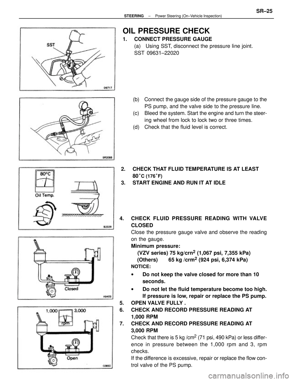
4. CHECK FLUID PRESSURE READING WITH VALVE
CLOSED
Close the pressure gauge valve and observe the reading
on the gauge.
Minimum pressure:
(VZV series) 75 kg/crn
2 (1,067 psi, 7,355 kPa)
(Others) 65 kg /crm
2 (924 psi, 6,374 kPa)
NOTICE:
wDo not keep the valve closed for more than 10
seconds.
wDo not let the fluid temperature become too high.
If pressure is low, repair or replace the PS pump.
5. OPEN VALVE FULLY .
6. CHECK AND RECORD PRESSURE READING AT
1,000 RPM
7. CHECK AND RECORD PRESSURE READING AT
3,000 RPM
Check that there is 5 kg /cm
2 (71 psi, 490 kPa) or less differ-
ence in pressure between the 1,000 rpm and 3, rpm
checks.
If the difference is excessive, repair or replace the flow con-
trol valve of the PS pump.(b) Connect the gauge side of the pressure gauge to the
PS pump, and the valve side to the pressure line.
(c) Bleed the system. Start the engine and turn the steer-
ing wheel from lock to lock two or three times.
(d) Check that the fluid level is correct.
OIL PRESSURE CHECK
1. CONNECT PRESSURE GAUGE
(a) Using SST, disconnect the pressure line joint.
SST 09631±22020
2. CHECK THAT FLUID TEMPERATURE IS AT LEAST
80
°C (176°F)
3. START ENGINE AND RUN IT AT IDLE
± STEERINGPower Steering (On±Vehicle Inspection)SR±25
Page 2352 of 2389
8. CHECK PRESSURE READING WITH STEERING
WHEEL TURNED TO FULL LOCK
Be sure the pressure gauge valve is fully opened and the
engine idling.
Minimum pressure:
(VZV series) 75 kg/cm
2 (1,067 psi, 7,355 kPa)
(Others) 65 kg/cm
2 (924 psi, 6,374 kPa)
NOTICE:
wDo not maintain lock position for more than 10
seconds.
wDo not let the fluid temperature become too high.
If pressure is tow, the gear housing has an internal leak
and must be repaired or replaced.
9. MEASURE STEERING EFFORT
Center the steering wheel and run the engine at idle.
Using a torque meter, measure the steering effort in both
directions.
Maximum steering effort: 70 kg±cm (61 in.±Ib, 6.9
N±m)
If steering effort is excessive, repair the power steering
unit.
HINT: Be sure to consider the tire type, pressure and con-
tact surface before making your diagnosis.
± STEERING± Power Steering (On±Vehicle Inspection)SR±26
Page 2353 of 2389
Power Steering Pump
REMOVAL AND INSTALLATION OF POWER
STEERING PUMP (SV21 Series)
Remove and install the parts as shown.
(MAIN POINT OF INSTALLATION)
ADJUST DRIVE BELT TENSION AFTER INSTALLING PS
PUMP
(See page SR±22)
± STEERINGPower Steering (Power Steering Pump)SR±27
Page 2354 of 2389
REMOVAL AND INSTALLATION OF
POWER STEERING PUMP (SV25 Series)
Remove and install the parts as shown.
± STEERINGPower Steering (Power Steering Pump)SR±28
Page 2355 of 2389
(MAIN POINTS OF REMOVAL AND
INSTALLATION)
1. DISCONNECT AND CONNECT PRESSURE LINE
Using SST, disconnect and connect the pressure line.
SST 09631±22020
HINT: When connecting, use a torque wrench with a ful-
crum length of 340 mm (13.39 in.).
3. REMOVE DRIVE BELT
(a) Loosen the adjusting bolt and the through bolt and
push the PS pump forward.
(b) Remove the drive belt. 2. DISCONNECT TIE ROD END RH
(a) Remove the cotter pin and nut.
(b) Using SST, disconnect the tie rod end RH.
SST 09610±55012
4. REMOVE PUMP BRACKET
(a) Remove the adjusting bolt.
(b) Remove the bolt and bracket.
5. REMOVE REAR PUMP STAY
Remove the two bolts and stay.
± STEERINGPower Steering (Power Steering Pump)SR±29
Page 2356 of 2389
6. REMOVE PS PUMP WITH PRESSURE TUBE
(a) Remove the through bolt.
(b) Remove the PS pump from the lower side of body.
± STEERINGPower Steering (Power Steering Pump)SR±30