Page 20 of 2389

ItemCapacity
Classification
Liters US qts
Imp. qts
Automatic
transaxle fluid
(w/o Differential
oil)A540E
Dry fill
Drain and refill5.9
2.56.2
2.65.2
2.2ATF DEXRON� II
A54H
Dry fill
Drain and refill7.0
3.37.4
3.56.2
2.9ATF type T (08886 - 00405) or equivalent
Differential oil
(w/ Automatic transaxle)
SV21 series
VZV21 series1.6
1.01.7
1.11.4
0.9ATF DEXRON� II
Transfer oil (A540H)
0.7
0.74 0.62
Recommended oil
Oil grade: API GL-5
Viscosity: SAE 75W-90 or 80W-90
SAE 90W
[above -18°C (0°F)]
SAE 80W
[below -18°C (0°F)]
Transaxle oil E50 (08885 - 80206) or
equivalent
Part tightenedkg-cm ft-lbN-m
Transfer right case y Oil strainer
Transfer left case y Rear wheel speed sensor
Transfer left case y Transfer inspection hole cover
Transfer left case y Drain plug
Transfer left case y Driven pinion bearing cage
Driven pinion bearing cage y Transfer extension housing
Transfer extension housing y Dynamic damper
Transfer right case y Oil pump cover
Transfer ring gear y Ring gear mounting case
Center differential control solenoid y Transfer valve body
Transfer valve body y Transfer left case
Neutral start switch bolt
Neutral start switch nut
Transfer assembly y Transaxle case48 in.-lb
48 in.-lb
12
29
29
19
19
69 in.-lb
71
10
8
48 in.-lb
61 in.-lb
51 55
55
160
400
400
260
260
80
985
145
11 0
55
70
7005.4
5.4
16
39
39
25
25
7.8
97
14
11
5.4
6.9
69
Torque Specifications (Cont'd)
LUBRICANT
- SERVICE SPECIFICATIONSAutomatic Transaxle Transfer (A540E A540H)A-9
Page 23 of 2389
Type of Transmission
A540E
A540H
Type of Engine
2VZ-FE
3S-FE
Torque ConverterStall Torque Ratio
1.9 : 1
2.0 : 1
Lock-Up Mechanism
Equipped
u
Gear Ratio1st Gear
2.810
u
2nd Gear
1.549
u
3rd Gear
1.000
u
O/D Gear
0.734
u
Reverse Gear
2.296
Number of Discs and
Plates (Disc/Plate)C
0O/D Direct Clutch
2/2
u
C
1Forward Clutch 4/4
u
C
2Direct Clutch 3/3
u
B
22nd Brake
3/3
u
B
3First & Reverse Brake 7/7 6/6
B
0O/D Brake
3/3
u
mm (in.)B1 Band Width
38 (1.50)
25 (0.98)
AT FType
ATF DEXRON� IIATF Type T or
equivalent
Capacity liter
(US qts, Imp. qts)A/T5.9 (6.2, 5.2)
7.0 (7.4, 6.2)
D/F1.0 (1.1, 0.9)
Transfer OilTypeTransaxle oil E50,
API GL5,
SAE 75W-90
or equivalent
Capacity liter (US qts, Imp. qts)
0.7 (0.7, 0.6)
General Specification
u
AT-4- AUTOMATIC TRANSAXLEDescription
Page 455 of 2389
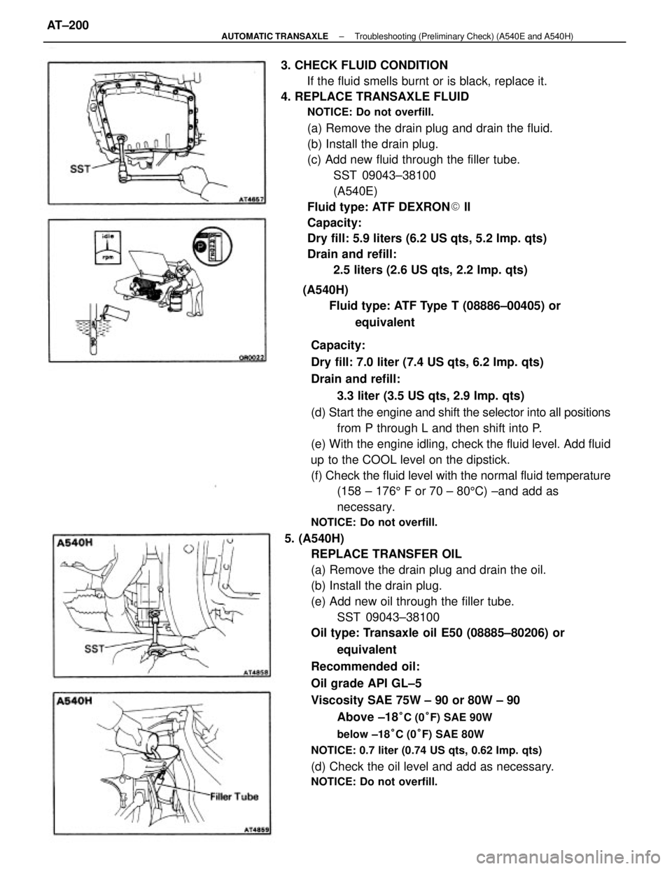
Capacity:
Dry fill: 7.0 liter (7.4 US qts, 6.2 Imp. qts)
Drain and refill:
3.3 liter (3.5 US qts, 2.9 Imp. qts)
(d) Start the engine and shift the selector into all positions
from P through L and then shift into P.
(e) With the engine idling, check the fluid level. Add fluid
up to the COOL level on the dipstick.
(f) Check the fluid level with the normal fluid temperature
(158 ± 1765 F or 70 ± 805C) ±and add as
necessary.
NOTICE: Do not overfill.
5. (A540H)
REPLACE TRANSFER OIL
(a) Remove the drain plug and drain the oil.
(b) Install the drain plug.
(e) Add new oil through the filler tube.
SST 09043±38100
Oil type: Transaxle oil E50 (08885±80206) or
equivalent
Recommended oil:
Oil grade API GL±5
Viscosity SAE 75W ± 90 or 80W ± 90
Above ±18
°C (0°F) SAE 90W
below ±18°C (0°F) SAE 80W
NOTICE: 0.7 liter (0.74 US qts, 0.62 Imp. qts)
(d) Check the oil level and add as necessary.
NOTICE: Do not overfill.
3. CHECK FLUID CONDITION
If the fluid smells burnt or is black, replace it.
4. REPLACE TRANSAXLE FLUID
NOTICE: Do not overfill.
(a) Remove the drain plug and drain the fluid.
(b) Install the drain plug.
(c) Add new fluid through the filler tube.
SST 09043±38100
(A540E)
Fluid type: ATF DEXRON� ll
Capacity:
Dry fill: 5.9 liters (6.2 US qts, 5.2 Imp. qts)
Drain and refill:
2.5 liters (2.6 US qts, 2.2 Imp. qts)
(A540H)
Fluid type: ATF Type T (08886±00405) or
equivalent
± AUTOMATIC TRANSAXLETroubleshooting (Preliminary Check) (A540E and A540H)AT±200
Page 1251 of 2389
26. INSTALL OIL PRESSURE SWITCH, ENGINE HANGERS
AND ALTERNATOR BRACKET
Torque the bolts.
Torque: 500 kg±cm (37 ft±Ib, 48 N±m)
27. INSTALL ALTERNATOR (See page CH±14)
28. INSTALL AIR CLEANER HOSE
29. INSTALL CRUISE CONTROL ACTUATOR
(See step 26 on page EM±137)
30. INSTALL RADIATOR RESERVOIR TANK
31. INSTALL ACCELERATOR CABLE, AND ADJUST IT
32. (A/T)
CONNECT THROTTLE CABLE, AND ADJUST IT
33. FILL WITH ENGINE COOLANT (See page CO±5)
Capacity (w/ Heater):
M/T 6.4 liters (6.8 US qts, 5.6 Imp. qts)
A/T (2WD) 6.3 liters (6.7 US qts, 5.5 Imp. qts)
A/T (4WD) 6.8 liters (7.2 US qts, 6.0 Imp. qts)
34. CONNECT CABLE TO NEGATIVE TERMINAL OF
BATTERY
35. START ENGINE AND CHECK FOR LEAKS
36. PERFORM ENGINE ADJUSTMENT
(a) Adjust the valve clearance. (See page EM±11)
Valve clearance (Cold):
Intake 0.19 ± 0.29 mm (0.007 ± 0.011 in.)
Exhaust 0.28 ± 0.38 mm (0.011 ± 0.015 in.)
(b) Adjust the ignition timing.
(See steps 7 to 10 on pages IG±16 and 17)
Ignition timing:
10° BTDC @ idle
(w/ Terminals TE 1 and E 1 connected)
37. CHECK TOE±IN (See page FA±5)
38. PERFORM ROAD TEST
Check for abnormal noise, shock, slippage, correct shift
points and smooth operation.
39. RECHECK ENGINE COOLANT LEVEL AND OIL LEVEL
± ENGINE MECHANICALCylinder Head (3S±FE)EM±74
Page 1283 of 2389
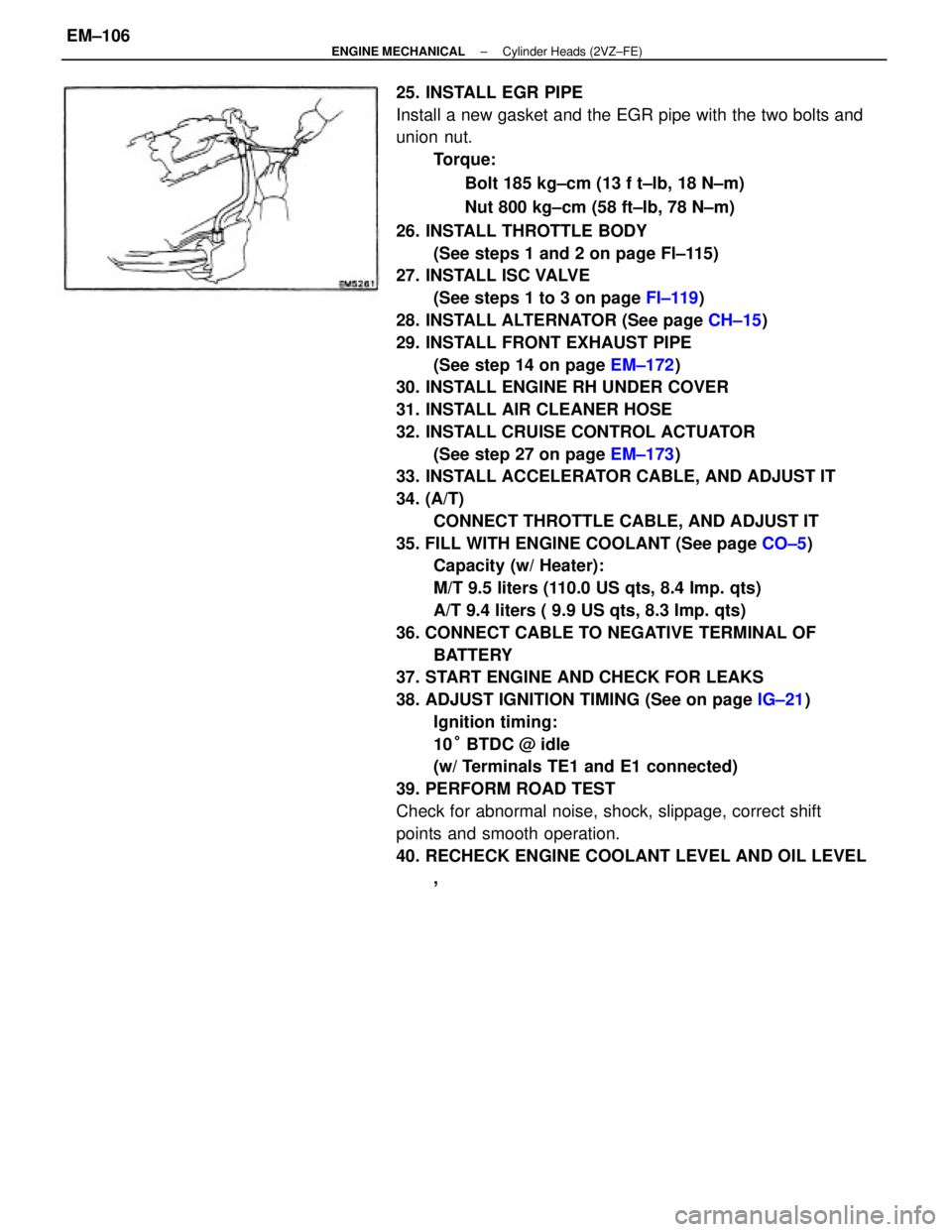
25. INSTALL EGR PIPE
Install a new gasket and the EGR pipe with the two bolts and
union nut.
Torque:
Bolt 185 kg±cm (13 f t±lb, 18 N±m)
Nut 800 kg±cm (58 ft±Ib, 78 N±m)
26. INSTALL THROTTLE BODY
(See steps 1 and 2 on page Fl±115)
27. INSTALL ISC VALVE
(See steps 1 to 3 on page FI±119)
28. INSTALL ALTERNATOR (See page CH±15)
29. INSTALL FRONT EXHAUST PIPE
(See step 14 on page EM±172)
30. INSTALL ENGINE RH UNDER COVER
31. INSTALL AIR CLEANER HOSE
32. INSTALL CRUISE CONTROL ACTUATOR
(See step 27 on page EM±173)
33. INSTALL ACCELERATOR CABLE, AND ADJUST IT
34. (A/T)
CONNECT THROTTLE CABLE, AND ADJUST IT
35. FILL WITH ENGINE COOLANT (See page CO±5)
Capacity (w/ Heater):
M/T 9.5 liters (110.0 US qts, 8.4 Imp. qts)
A/T 9.4 liters ( 9.9 US qts, 8.3 Imp. qts)
36. CONNECT CABLE TO NEGATIVE TERMINAL OF
BATTERY
37. START ENGINE AND CHECK FOR LEAKS
38. ADJUST IGNITION TIMING (See on page IG±21)
Ignition timing:
10° BTDC @ idle
(w/ Terminals TE1 and E1 connected)
39. PERFORM ROAD TEST
Check for abnormal noise, shock, slippage, correct shift
points and smooth operation.
40. RECHECK ENGINE COOLANT LEVEL AND OIL LEVEL
,
± ENGINE MECHANICALCylinder Heads (2VZ±FE)EM±106
Page 1315 of 2389
32. INSTALL BATTERY
33. FILL WITH ENGINE COOLANT (See page CO±5)
Capacity (w/ Heater):
M/T 6.4 liters (6.8 US qts, 5.6 Imp. qts)
A/T (2WD) 6.3 liters (6.7 US qts, 5.5 Imp. qts)
A/T (4WD) 6.8 liters (7.2 US qts, 6.0 Imp. qts)
34. FILL WITH ENGINE OIL (See page LU±8)
Capacity:
Drain and refill
w/ Oil filter change
3.9 liters (4.1 US qts, 3.4 Imp. qts)
w/o Oil filter change
3.7 liters (3.9 US qts, 3.3 Imp. qts)
Dry fill 4.3 liters (4.5 US qts, 3.8 Imp. qts)
35. START ENGINE AND CHECK FOR LEAKS
36. PERFORM ENGINE ADJUSTMENT
(a) Adjust the alternator drive belt.
(See page CH±3)
Drive belt tension:
w/ A/C New belt 175 + 5 lb
Used belt 130 + 10 lb
w/o A/C New belt 125 + 25 lb
Used belt 95 + 20 lb
(b) Adjust the PS drive belt.
Drive belt tension: New belt 125 + 25 lb
Used belt 80 + 20 lb
(c) Adjust the ignition timing.
(See steps 7 to 10 on pages IG±16 and 17)
Ignition timing:
10° BTDC @ idle
(w/ Terminals TE 1 and E1 connected)
(d) Adjust the valve. clearance. (See page EM±11)
Valve clearance:
Intake 0.19 ± 0.29 mm (0.007 ± 0.011 in.)
Exhaust 0.28 ± 0.38 mm (0.011 ± 0.015 in.)
37. INSTALL HOOD
38. PERFORM ROAD TEST
Check for abnormal noise, shock, slippage, correct shift
points and smooth operation.
39. RECHECK ENGINE COOLANT AND ENGINE OIL
LEVELS
± ENGINE MECHANICALCylinder Block (3S±FE)EM±138
Page 1351 of 2389
28. (A/T)
INSTALL THROTTLE CABLE, AND ADJUST IT
29. INSTALL ACCELERATOR CABLE, AND ADJUST IT
30. INSTALL RADIATOR RESERVOIR TANK
31. INSTALL ALTERNATOR BELT ADJUSTING BAR
32. INSTALL ALTERNATOR (See page CH±15)
33. INSTALL RADIATOR (See page CO±20)
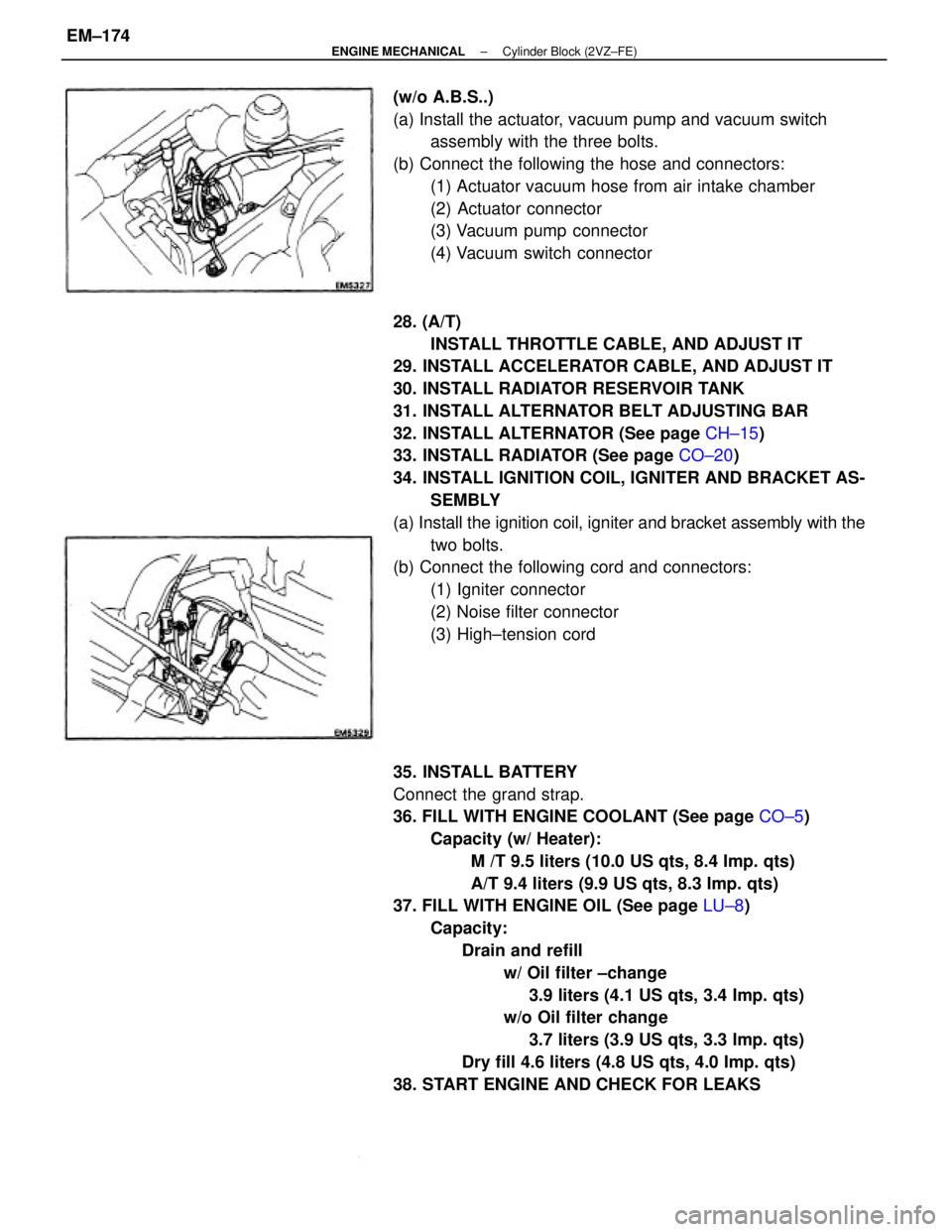
34. INSTALL IGNITION COIL, IGNITER AND BRACKET AS-
SEMBLY
(a) Install the ignition coil, igniter and bracket assembly with the
two bolts.
(b) Connect the following cord and connectors:
(1) Igniter connector
(2) Noise filter connector
(3) High±tension cord
35. INSTALL BATTERY
Connect the grand strap.
36. FILL WITH ENGINE COOLANT (See page CO±5)
Capacity (w/ Heater):
M /T 9.5 liters (10.0 US qts, 8.4 Imp. qts)
A/T 9.4 liters (9.9 US qts, 8.3 Imp. qts)
37. FILL WITH ENGINE OIL (See page LU±8)
Capacity:
Drain and refill
w/ Oil filter ±change
3.9 liters (4.1 US qts, 3.4 Imp. qts)
w/o Oil filter change
3.7 liters (3.9 US qts, 3.3 Imp. qts)
Dry fill 4.6 liters (4.8 US qts, 4.0 Imp. qts)
38. START ENGINE AND CHECK FOR LEAKS (w/o A.B.S..)
(a) Install the actuator, vacuum pump and vacuum switch
assembly with the three bolts.
(b) Connect the following the hose and connectors:
(1) Actuator vacuum hose from air intake chamber
(2) Actuator connector
(3) Vacuum pump connector
(4) Vacuum switch connector
± ENGINE MECHANICALCylinder Block (2VZ±FE)EM±174
Page 1396 of 2389
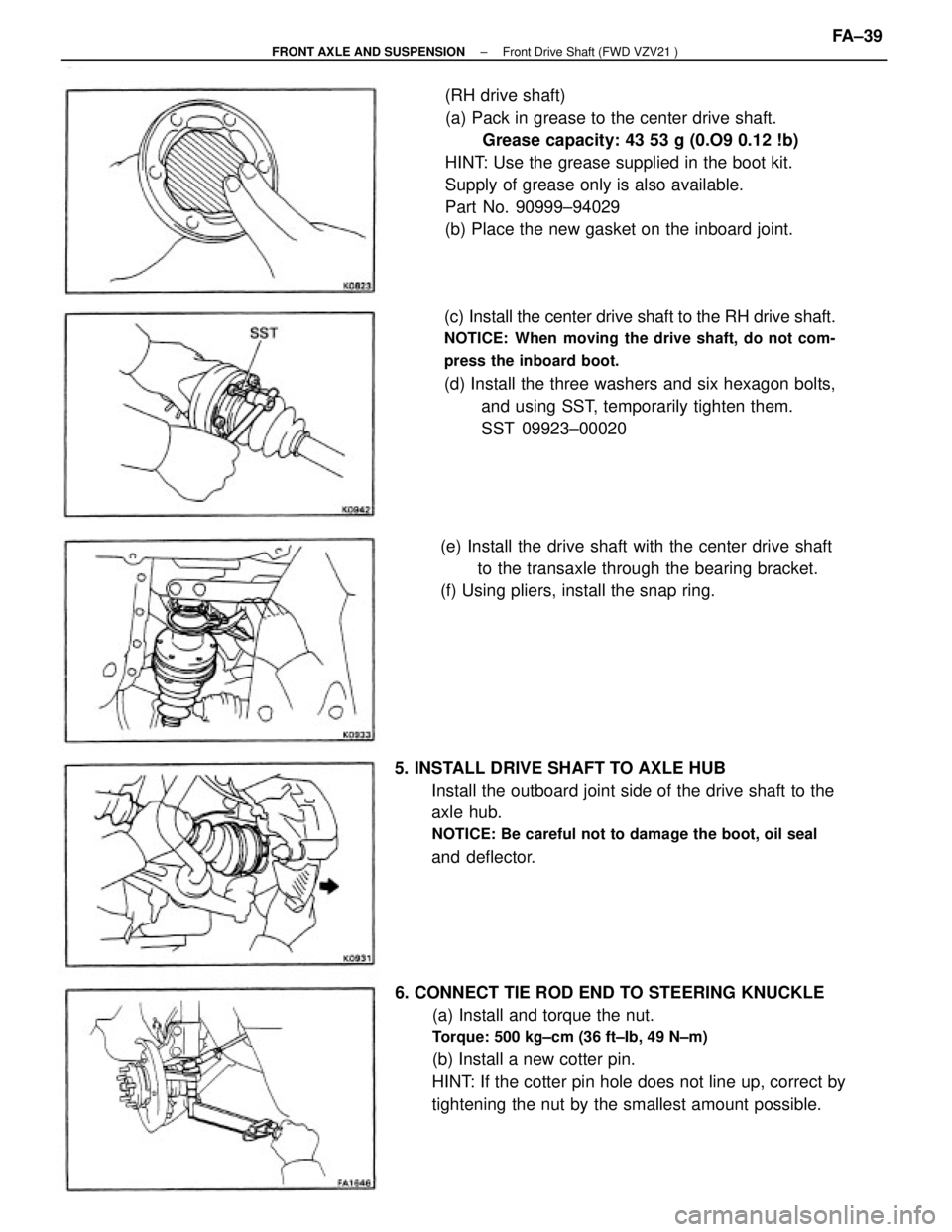
(RH drive shaft)
(a) Pack in grease to the center drive shaft.
Grease capacity: 43 53 g (0.O9 0.12 !b)
HINT: Use the grease supplied in the boot kit.
Supply of grease only is also available.
Part No. 90999±94029
(b) Place the new gasket on the inboard joint.
6. CONNECT TIE ROD END TO STEERING KNUCKLE
(a) Install and torque the nut.
Torque: 500 kg±cm (36 ft±Ib, 49 N±m)
(b) Install a new cotter pin.
HINT: If the cotter pin hole does not line up, correct by
tightening the nut by the smallest amount possible.(c) Install the center drive shaft to the RH drive shaft.
NOTICE: When moving the drive shaft, do not com-
press the inboard boot.
(d) Install the three washers and six hexagon bolts,
and using SST, temporarily tighten them.
SST 09923±00020
5. INSTALL DRIVE SHAFT TO AXLE HUB
Install the outboard joint side of the drive shaft to the
axle hub.
NOTICE: Be careful not to damage the boot, oil seal
and deflector.(e) Install the drive shaft with the center drive shaft
to the transaxle through the bearing bracket.
(f) Using pliers, install the snap ring.
± FRONT AXLE AND SUSPENSIONFront Drive Shaft (FWD VZV21 )FA±39