Page 27 of 2389

VALVE BODY
Hydraulic Control System
� A540E, A540H
The hydraulic control system is composed of the oil pump, the valve body, the solenoid valves, the accu-
mulators, the clutches and brakes, and the governor valve as well as the fluid passages which connect all
of these components.
Based on the hydraulic pressure created by the oil pump, the hydraulic control system governs the hy-
draulic pressure acting on the torque converter, clutches and brakes in accordance with the vehicle driving
conditions.
There are three solenoid valves on the valve body.
The No. 1 and No. 2 solenoid valves are turned on and off by signals from ECU to operate the shift valves
and change the gear shift position.
The No. 3 solenoid valve is operated by signals from the ECU to engage or disengage the lock-up clutch
of the torque converter.
� A540H
There are two center differential control solenoid valves on the transfer.
The solenoid valves are adjusting the center differential control pressure.
HYDRAULIC CONTROL SYSTEM
Hydr. pressure control
OIL PUMP
CLUTCHES & BRAKESFluid passage switchingPlanetary gear unit
Torque converter
Throttle Cable
SOLENOID VALVES
ECU
AT-8- AUTOMATIC TRANSAXLEOperation
Page 104 of 2389
AT3476
AT3477Lock-up Relay Valve PlugLock-up Relay
Control Valve RetainerRetainerSleeve Plug RetainerNo. 1 Accumulator
Control Valve PlugCut-back Valve
PlugRetainer Modulator Valve ThrottleSleeve PinDown-shift PlugValve Vibrating Stopper Oil Strainer RetainerThrottle ValvePlate Washer
Wave Washer B
1 orifice
Control Valve PlugCheck Ball PlugSpring Retainer 2nd Coast
Modulator Valve
The throttle pressure is changed
according to the number of adjusting
rings.
When assembling the valve body,
install the same number of adjusting
rings as were removed.
Adjusting Ring
Pin
Cam
(Upper Valve Body)
COMPONENTS
- AUTOMATIC TRANSAXLEComponent Parts (Valve Body)AT-89
Page 107 of 2389
(Lower Valve Body)
COMPONENTS
AT4502
AT3483
Retainer Plug3 - 4 Shift Valve PlugRetainer PlugRetainer PlugNo. 2 Accumulator
Control Valve Retainer
2nd lock ValveCheck Ball Secondary Regulator ValveCheck Valve
Oil Strainer Pressure Relief ValveCheck Ball
Plunger Sleeve
The line pressure changes
according to the part of
the plunger sleeve which
comes into contact with
the retainer.
When reassembling the
valve body, position the
retainer in the same
position.
Retainer PlugPlunger RetainerRetainer Shift Valve Plug PlugPrimary Regulator
Valve Plate Washer 2 - 3 Shift Valve Retainer1 - 2 Shift Valve Low Coast Modulator Valve
AT-92- AUTOMATIC TRANSAXLEComponent Parts (Valve Body)
Page 264 of 2389

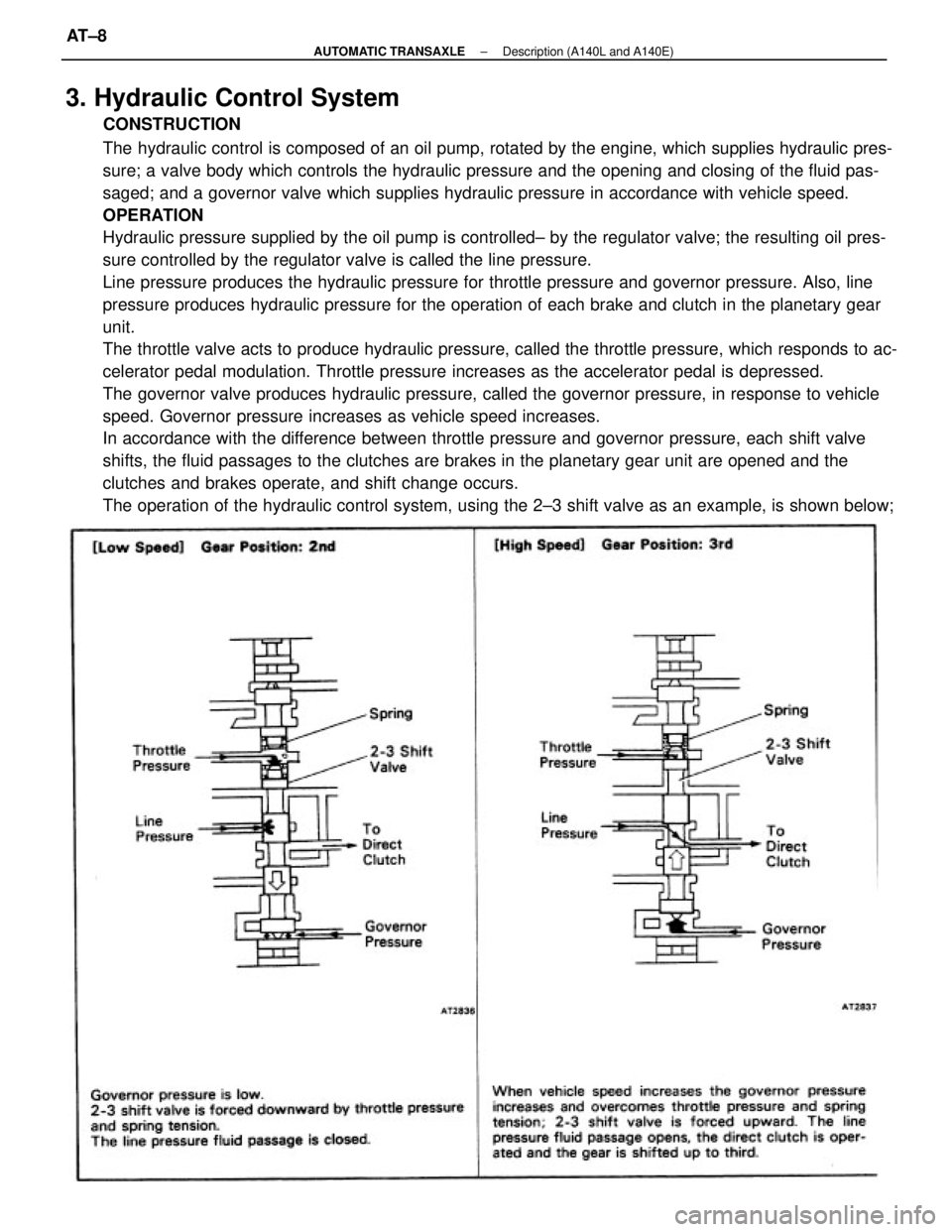
3. Hydraulic Control System
CONSTRUCTION
The hydraulic control is composed of an oil pump, rotated by the engine, which supplies hydraulic pres-
sure; a valve body which controls the hydraulic pressure and the opening and closing of the fluid pas-
saged; and a governor valve which supplies hydraulic pressure in accordance with vehicle speed.
OPERATION
Hydraulic pressure supplied by the oil pump is controlled± by the regulator valve; the resulting oil pres-
sure controlled by the regulator valve is called the line pressure.
Line pressure produces the hydraulic pressure for throttle pressure and governor pressure. Also, line
pressure produces hydraulic pressure for the operation of each brake and clutch in the planetary gear
unit.
The throttle valve acts to produce hydraulic pressure, called the throttle pressure, which responds to ac-
celerator pedal modulation. Throttle pressure increases as the accelerator pedal is depressed.
The governor valve produces hydraulic pressure, called the governor pressure, in response to vehicle
speed. Governor pressure increases as vehicle speed increases.
In accordance with the difference between throttle pressure and governor pressure, each shift valve
shifts, the fluid passages to the clutches are brakes in the planetary gear unit are opened and the
clutches and brakes operate, and shift change occurs.
The operation of the hydraulic control system, using the 2±3 shift valve as an example, is shown below;
± AUTOMATIC TRANSAXLEDescription (A140L and A140E)AT±8
Page 871 of 2389

8. INSTALL NEW PADS
(a) Install new pad wear indicator plate to inner pad.
NINT: Be sure the arrow on the pad wear indicator
plate is pointing i n the direction of the disc rotation.
(b) (Except 2VZ±FE Engine of w/ A.B.S.)
Install the one anti±squeal shim to the each pad.
(c) (For 2VZ±FE Engine of w/ A.B.S.)
Install the two anti±squeal shims to the each pad.
HINT: Apply disc brake grease to both side of the inner
anti±squeal shim of the outside pad.
(d) Install the pads onto each support plate.
NOTICE: Do not allow oil or grease to get on the
rubbing face.
(e) Install the two anti±squeal springs.
9. INSTALL CYLINDER
(a) Draw out a small amount of brake fluid from the reser-
voir.
(b) Press in piston with a hammer handle or an equiva-
lent.
HINT: Always change the pad on one wheel at a time as
there is a possibility of the opposite piston flying out.
(c) Insert the brake cylinder carefully ±so the boot is not
wedged. 5. CHECK ROTOR DISC THICKNESS
(See step 2 on page BR±23)
6. CHECK ROTOR DISC RUNOUT
(See step 3 on page BR±23)
7. INSTALL PAD SUPPORT PLATES
± BRAKE SYSTEMFront BrakeBR±20
Page 887 of 2389
9. INSTALL CYLINDER
(a) Draw out a small amount of brake fluid from the res-
ervoir.
(b) Press in piston with a hammer handle or an equiva-
lent.
HINT: Always change the pad on one wheel at a time as
there is a possibility of the opposite piston flying out.
(c) Insert the brake cylinder carefully so the boot is not
wedged. 8. INSTALL NEW PADS
(a) Install the two anti±squeal shims to the each pad.
HINT: Apply disc brake grease to the both side of the inner
anti±squeal shim.
(b) Install the two pads so the wear indicator plate is at
the bottom side.
NOTICE: Do not allow oil or grease to get on the rub±
bing face.
(d) Install and. torque the installation
bolt.
Torque: 200 kg±cm (14 ft±Ib, 20 N±m)
10. INSTALL REAR WHEEL
11. FILL BRAKE FLUID
± BRAKE SYSTEMRear BrakeBR±36
Page 934 of 2389

(d) Jack up the front side of the vehicle slowly as shown.
HINT: When measuring the height, measure at the center
of the lower body or spoiler edge of the vehicle.
(e) Check that the warning light does not turn on.
(f) Jack down the vehicle and check that the warning
light blinking.
If the warning light turns on, inspect the deceleration se
sor installation. And if the sensor installation is ±OK, r
place the deceleration sensor.
(e) Drive the vehicle straight ahead at about 20 km/h
(12.4 mph) or more, depress the brake pedal strong±
ly.
(f) Check that the warning light light pattern changes af-
ter braking as shown.
If the operation is not as specified, inspect the deceleration
sensor installation. And if the sensor installation is OK, r
place the deceleration sensor. 5. INSPECT SENSOR OPERATION
(a) Drive the vehicle straight ahead at about 10 km/h l6.2
mph) or more, lightly depress the brake pedal.
(b) Check that there is no change in the warning light
light pattern.
(c) Drive the vehicle straight ahead at about 20 km/h
(12.4 mph) or more, depress the brake pedal a little
strong.
(d) Check that the warning light turns on while braking.
6. REMOVE SHORT PIN
(a) Stop the engine.
(b) Remove the short pin or wire from the Ts connector.
(c) Install the rubber cap to the Ts connector.
± BRAKE SYSTEMAnti±lock Brake System (A.B.S.)BR±83
Page 1024 of 2389

TROUBLESHOOTING
TROUBLESHOOTING HINTS
1. Engine troubles is usually not caused by the EFI system.
When troubleshooting, always first check the condition of
the other systems.
(a) Electronic source
wBattery
wFusible links
wFuses
(b) Body ground
(e) Fuel supply
wFuel leakage
wFuel filter
wFuel pump
(d) Ignition system
wSpark plugs
wHigh±tension cords
wDistributor
wIgnition coil
wIgniter
(e) Air induction system
wVacuum leaks
(f) Emission control system
wPCV system
wEGR system
(g) Others
wIgnition timing (ESA system)
wdle speed (ISC system)
wetc.
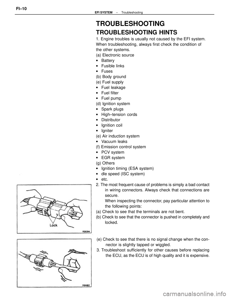
2. The most frequent cause of problems is simply a bad contact
in wiring connectors. Always check that connections are
secure.
When inspecting the connector, pay particular attention to
the following points:
(a) Check to see that the terminals are not bent.
(b) Check to see that the connector is pushed in completely and
locked.
(e) Check to see that there is no signal change when the con-
nector is slightly tapped or wiggled.
3. Troubleshoot sufficiently for other causes before replacing
the ECU, as the ECU is of high quality and it is expensive.
± EFI SYSTEMTroubleshootingFI±10