Page 1918 of 2389

6. REPLACE ENGINE OIL AND OIL FILTER
(See page LU±7)
Oil grade: API grade SG, multigrade, fuel±efficient and
recommended viscosity oil
Drain and refill with oil filter change capacity:
3.9 liters (4.1 US qts, 3.4 Imp. qts)
7. REPLACE ENGINE COOLANT
(See page CO±4)
Use a good brand of ethylene±glycol base coolant, mixed
according to the manufacturer's instructions.
Coolant capacity (w/ Heater):
3S±FE M/T 6.4 liters (6.8 US qts, 5.6 Imp. qts)
A/T (2WD)
6.3 liters (6.7 US qts, 5.5 Imp. qts)
A/T (4WD)
6.8 liters (7.2 US qts. 6.0 Imp. qts)
2VZ±FE M/T 9.5 liters (10.0 US qts, 8.4 Imp. qts)
A/T 9.4 liters (9.9 US qts, 8.3 Imp. qts)
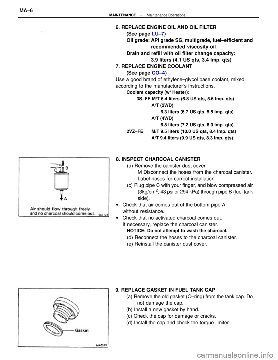
8. INSPECT CHARCOAL CANISTER
(a) Remove the canister dust cover.
M Disconnect the hoses from the charcoal canister.
Label hoses for correct installation.
(c) Plug pipe C with your finger, and blow compressed air
(3kg/cm
2, 43 psi or 294 kPa) through pipe B (fuel tank
side).
wCheck that air comes out of the bottom pipe A
without resistance.
wCheck that no activated charcoal comes out.
If necessary, replace the charcoal canister.
NOTICE: Do not attempt to wash the charcoal.
(d) Reconnect the hoses to the charcoal canister.
(e) Reinstall the canister dust cover.
9. REPLACE GASKET IN FUEL TANK CAP
(a) Remove the old gasket (O±ring) from the tank cap. Do
not damage the cap.
(b) Install a new gasket by hand.
(c) Check the cap for damage or cracks.
(d) Install the cap and check the torque limiter.
± MAINTENANCEMaintenance OperationsMA±6
Page 2213 of 2389
Front and rear brake
Pad thickness
Disc thickness
Disc runout
Parking brake
Lining thickness
Drum inside diameter
Front axle and suspension
Ball joint vertical play
Steering wheel freeplay
Torque specifications
Front seat mount bolts
Strut/stabilizer bar bracket x Body
Engine mounting center member x Body
Front suspension lower crossmember x Body
Rear suspension lower crossmember x Body
MAINTENANCE
Engine
Engine oil capacity (Drain and refill with oil fitter change)
Gap
Firing order
Valve clearance Coolant capacity 1w/ Heater) Drive belt tension
Alternator
Spark plug
Type
Chassis
PS pump
± SERVICE SPECIFICATIONSMaintenanceA±2
Page 2235 of 2389
Dry fill 3S±FE
2VZ± FE
Drain and refill
w/ Oil filter changeAPI grade SG, multigrade,
recommended viscosity and fuel±efficient oil
w/o Oil filter change Engine oil
LUBRICANT
Classification Ca pa city
Imp. qts
US qts Liters Item
± SERVICE SPECIFICATIONSLubricantA±20
Page 2336 of 2389

SERVICE HINT
Troubles with the power steering system are usually
concerned with hard steering due to the fact that
there is no assist. In such cases, before attempting
to make repairs, it is necessary to determine wheth-
er the trouble lies with the pump or with the gear
housing. To do this, an on±vehicle inspection can be
made by using a pressure gauge.
ON±VEHICLE INSPECTION
Power steering is a hydraulic device and problems
are normally due to insufficient fluid pressure acting
on the piston. This could be caused by either the
pump not producing the specified fluid pressure or
the control valve in the gear housing not functioning
properly so that the proper fluid pressure can not be
obtained.
If the fault lies with the pump, the same symptoms
will generally occur whether the steering wheel is
turned fully to the right or left. On the other hand, if
the fault lies with the control valve, there will gener-
ally be difference between the amount of assist
when the steering wheel is turned to the left and
right, causing harder steering. However, if the piston
seal of the power cylinder is worn, there will be a
loss of fluid pressure whether the steering wheel is
turned to the right or left and the symptoms will be
the same for both.
Before performing an on±vehicle inspection, a
check must first be made to confirm that the power
steering system is completely free of any air. If there
is any air in the system, the volume of this air wilt
change when the fluid pressure raised, causing a
fluctuation in the fluid pressure so that the power
steering will not function properly. To determine if
there is any air in the system, check to see if there
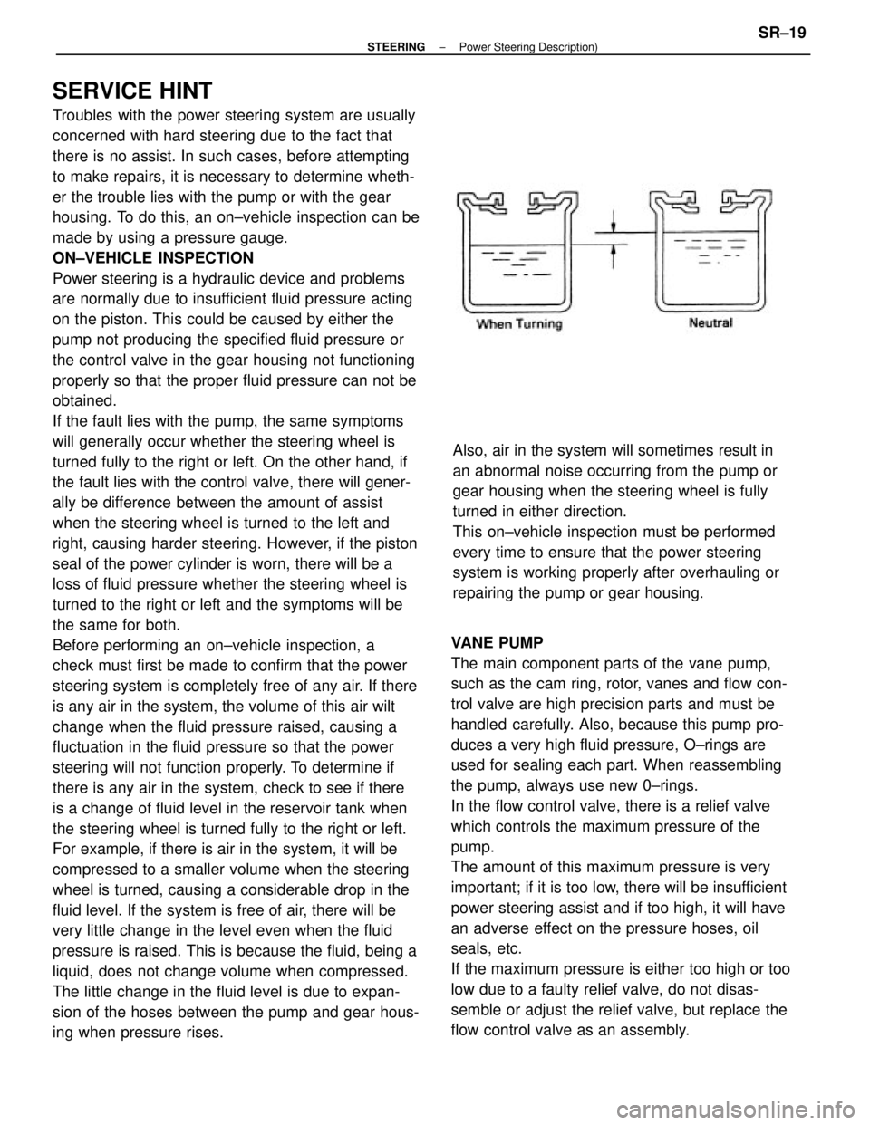
is a change of fluid level in the reservoir tank when
the steering wheel is turned fully to the right or left.
For example, if there is air in the system, it will be
compressed to a smaller volume when the steering
wheel is turned, causing a considerable drop in the
fluid level. If the system is free of air, there will be
very little change in the level even when the fluid
pressure is raised. This is because the fluid, being a
liquid, does not change volume when compressed.
The little change in the fluid level is due to expan-
sion of the hoses between the pump and gear hous-
ing when pressure rises.VANE PUMP
The main component parts of the vane pump,
such as the cam ring, rotor, vanes and flow con-
trol valve are high precision parts and must be
handled carefully. Also, because this pump pro-
duces a very high fluid pressure, O±rings are
used for sealing each part. When reassembling
the pump, always use new 0±rings.
In the flow control valve, there is a relief valve
which controls the maximum pressure of the
pump.
The amount of this maximum pressure is very
important; if it is too low, there will be insufficient
power steering assist and if too high, it will have
an adverse effect on the pressure hoses, oil
seals, etc.
If the maximum pressure is either too high or too
low due to a faulty relief valve, do not disas-
semble or adjust the relief valve, but replace the
flow control valve as an assembly.Also, air in the system will sometimes result in
an abnormal noise occurring from the pump or
gear housing when the steering wheel is fully
turned in either direction.
This on±vehicle inspection must be performed
every time to ensure that the power steering
system is working properly after overhauling or
repairing the pump or gear housing.
± STEERINGPower Steering Description)SR±19
Page 2385 of 2389
5. AIR TIGHTNESS TEST
(a) Install SST to the union of the cylinder housing.
SST 09631±12070
(b) Apply 400 mm Hg (15.75 in. Hg, 53.3 kPa) of vacuum
for about 30 seconds.
(c) Check that there is no change in the vacuum. 4. INSTALL CYLINDER END STOPPER, OIL SEAL AND
SPACER
(a) To prevent oil seal lip damage, wind vinyl tape on the
steering rack end, and apply power steering fluid.
(b) Install the oil seal by pushing it into the cylinder in the
direction shown in drawing, without tilting.
(c) Install the spacer and cylinder end stopper.
(d) Using SST, drive in the cylinder end stopper.
SST 09612±22011(b) Coat SST with power steering fluid.
(c) Insert the rack into the cylinder.
(d) Remove SST.
(e) Using snap ring pliers, install the snap ring.
± STEERINGPower Steering (Gear Housing)SR±59
Page:
< prev 1-8 9-16 17-24