1986 TOYOTA CAMRY V20 ad blue
[x] Cancel search: ad bluePage 15 of 2389

Accumulator
spring
SpringFree length
mm (in.)Coil outer
diameter
mm (in.)Total
No. of
coilsColor
Inner
Outer C
143.4 (1.709)
71.2 (2.803)17.8 (0.701)
24.4 (0.961)9.0
11.5Light Green
Blue
C
251.0 (2.008)
18.0 (0.709)
10.2
Red
C
0
(O/D case)Inner
Outer47.5 (1.870)
59.3 (2.335)18.9 (0.744)
25.5 (1.004)9.5
9.5White
Gray
B
258.5 (2.303)
15.2 (0.598)
15.9
Orange
B
0 (Valve body)
62.2 (2.449)
14.8 (0.583)
17.0
None
Differential
Side bearing adjusting shim thickness Drive pinion preload (at starting)
New Bearing
Reused bearing
Total preload (at starting)
New bearing
Reused bearing
Pinion to side gear backlash
Side gear thrust washer thickness
Mark
0
1
2
3
4
5
6
7
8
9
A
B
C
D
E
F
G
H0.0787 in.
0.0807 in.
0.0827 in.
0.0846 in.
0.0866 in.
0.0886 in.
0.0906 in.
0.0925 in.
0.0945 in.
0.0965 in.
0.0984 in.
0.1004 in.
0.1024 in.
0.1043 in.
0.1063 in.
0.1083 in.
0.1103 in.
0.1122 in. 2.00 mm
2.05 mm
2.10 mm
2.15 mm
2.20 mm
2.25 mm
2.30 mm
2.35 mm
2.40 mm
2.45 mm
2.50 mm
2.55 mm
2.60 mm
2.65 mm
2.70 mm
2.75 mm
2.80 mm
2.85 mm 10 - 16 kg-cm 8.7 - 13.9 in.-lb 1.0 - 1.6 N-m
5 - 8 kg-cm 4.3 - 6.9 in.-lb 0.5 - 0.8 N-m
Add drive pinion preload
2.8 - 4.4 kg-cm 2.4 - 3.8 in.-lb 0.3 - 0.4 N-m
1.4 - 2.2 kg-cm 1.2 - 1.9 in.-lb 0.1 - 0.2 N -
0.05 - 0.20 mm 0.0020 - 0.0079 in.
0.80 mm 0.0315 in.
0.90 mm 0.0354 in.
1.00 mm 0.0394 in.
1.10 mm 0.0433 in.
1.20 mm 0.0472 in.
1.30 mm 0.0512 in.
1.40 mm 0.0551 in.
Specifications (Cont'd)
A-4- SERVICE SPECIFICATIONSAutomatic Transaxle Transfer (A540E A540H)
Page 157 of 2389

AT3737
C1
B2C2
AT3539
SpringFree length
mm (in.)Outer diameter
mm (in.)Color
C
251.0 (2.008)18.0 (0.709)
Red
B
258.5 (2.303)15.2 (0.598)
Orange
C
1
Outer71.2 (2.803)24.4 (0.961)
Blue
Inner43.4 (1.709)17.8 (0.701)
Light green
AT3537
AT3536 AT3538
30. INSTALL ACCUMULATOR PISTONS AND SPRINGS
(a) Install the new O-rings to the pistons.
(b) Install the springs and pistons into the bores.
(c) Place the cover with a new gasket and gradually
tighten the bolts a little a time in sequence.
HINT: Each bolt length (mm, in.) is indicated in the figure.
Torque: 100 kg-cm (7 ft-lb, 10 N-m)
31. PLACE NEW SECOND BRAKE APPLY GASKET
32. INSTALL THROTTLE CABLE AND SOLENOID WIRE
33. INSTALL VALVE BODY TO TRANSAXLE CASE
(a) While holding the cam down with your hand, slip
the cable end into the slot.
(b) Lower the valve body into place.
NOTICE: Do not entangle the solenoid wire.
- AUTOMATIC TRANSAXLEInstallation of Component PartsAT-141
Page 748 of 2389

GENERAL INFORMATION
WIRING COLOR CODE
Wire colors are indicated by an alphabetical code.
B =Black L =Blue R =Red
BR=Brown LG=Light Green V =Violet
G =Green O =Orange W=White
GR=Gray P =Pink Y =Yellow
The first letter indicates the basic wire color and the sec±
ond letter indicates the color of the stripe.
CONNECTOR
1. PIN NUMBER OF FEMALE CONNECTOR
Numbered in order from upper left to lower right.
2. PIN NUMBER OF MALE CONNECTOR
Numbered in order from upper right to lower left.
3. DISTINCTION OF MALE AND FEMALE CONNECTORS
Male and female connectors are distinguished by shape
of their internal pins.
(a) All connectors are shown from the open end, and the
lock is on top.
(b) To pull apart the connectors, pull on the connector it-
self, not the wires.
HINT: Check the type of connector before disconnecting.
± BODY ELECTRICAL SYSTEMGeneral informationBE±2
Page 1238 of 2389
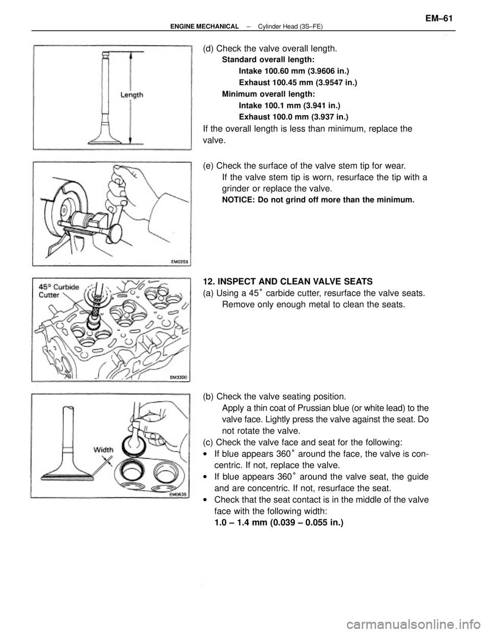
(b) Check the valve seating position.
Apply a thin coat of Prussian blue (or white lead) to the
valve face. Lightly press the valve against the seat. Do
not rotate the valve.
(c) Check the valve face and seat for the following:
wIf blue appears 360° around the face, the valve is con-
centric. If not, replace the valve.
wIf blue appears 360° around the valve seat, the guide
and are concentric. If not, resurface the seat.
wCheck that the seat contact is in the middle of the valve
face with the following width:
1.0 ± 1.4 mm (0.039 ± 0.055 in.) (d) Check the valve overall length.
Standard overall length:
Intake 100.60 mm (3.9606 in.)
Exhaust 100.45 mm (3.9547 in.)
Minimum overall length:
Intake 100.1 mm (3.941 in.)
Exhaust 100.0 mm (3.937 in.)
If the overall length is less than minimum, replace the
valve.
(e) Check the surface of the valve stem tip for wear.
If the valve stem tip is worn, resurface the tip with a
grinder or replace the valve.
NOTICE: Do not grind off more than the minimum.
12. INSPECT AND CLEAN VALVE SEATS
(a) Using a 45° carbide cutter, resurface the valve seats.
Remove only enough metal to clean the seats.
± ENGINE MECHANICALCylinder Head (3S±FE)EM±61
Page 1266 of 2389
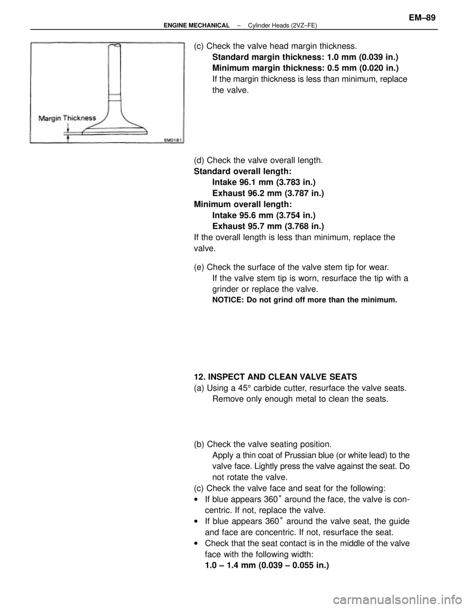
(b) Check the valve seating position.
Apply a thin coat of Prussian blue (or white lead) to the
valve face. Lightly press the valve against the seat. Do
not rotate the valve.
(c) Check the valve face and seat for the following:
wIf blue appears 360° around the face, the valve is con-
centric. If not, replace the valve.
wIf blue appears 360° around the valve seat, the guide
and face are concentric. If not, resurface the seat.
wCheck that the seat contact is in the middle of the valve
face with the following width:
1.0 ± 1.4 mm (0.039 ± 0.055 in.) (d) Check the valve overall length.
Standard overall length:
Intake 96.1 mm (3.783 in.)
Exhaust 96.2 mm (3.787 in.)
Minimum overall length:
Intake 95.6 mm (3.754 in.)
Exhaust 95.7 mm (3.768 in.)
If the overall length is less than minimum, replace the
valve. (c) Check the valve head margin thickness.
Standard margin thickness: 1.0 mm (0.039 in.)
Minimum margin thickness: 0.5 mm (0.020 in.)
If the margin thickness is less than minimum, replace
the valve.
(e) Check the surface of the valve stem tip for wear.
If the valve stem tip is worn, resurface the tip with a
grinder or replace the valve.
NOTICE: Do not grind off more than the minimum.
12. INSPECT AND CLEAN VALVE SEATS
(a) Using a 455 carbide cutter, resurface the valve seats.
Remove only enough metal to clean the seats.
± ENGINE MECHANICALCylinder Heads (2VZ±FE)EM±89
Page 1422 of 2389
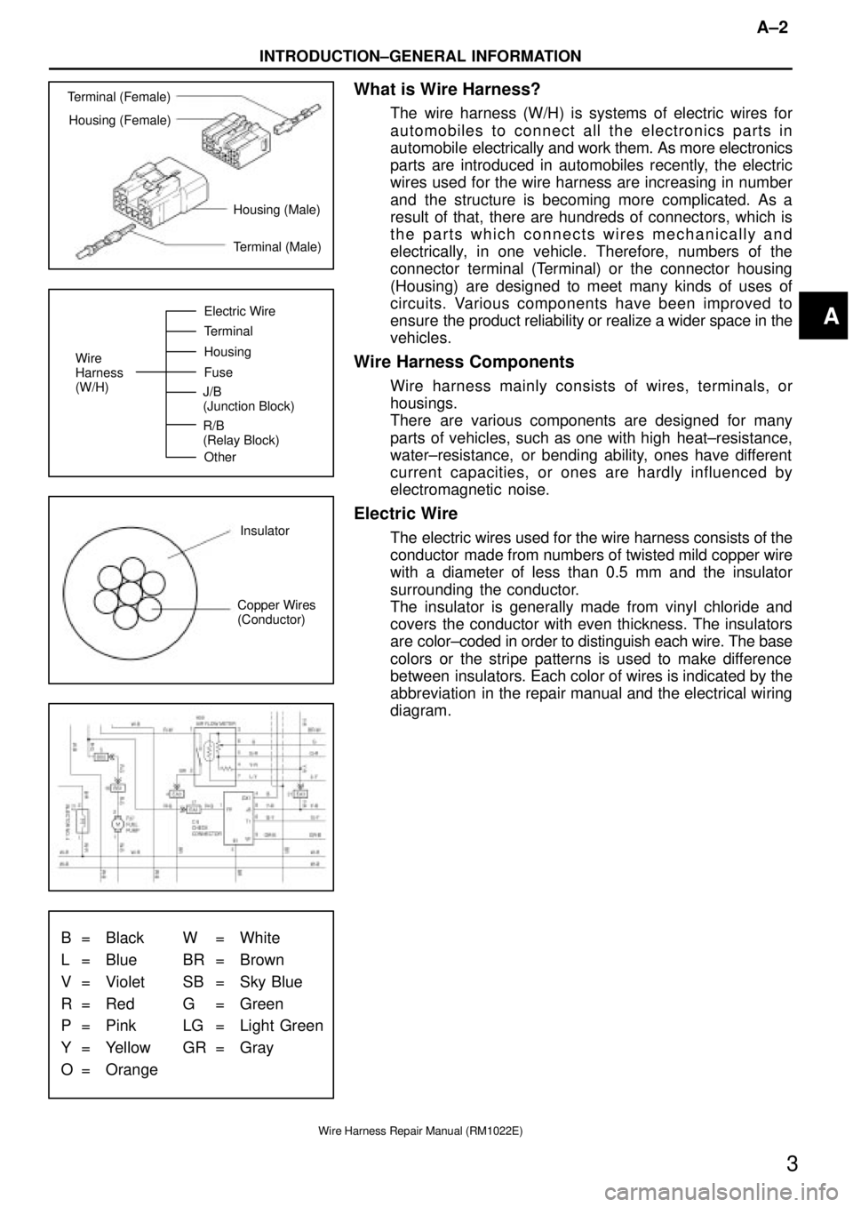
Terminal (Female)
Housing (Female)
Housing (Male)
Terminal (Male)
Wire
Harness
(W/H)Electric Wire
Terminal
Housing
Fuse
Other J/B
(Junction Block)
R/B
(Relay Block)
Insulator
Copper Wires
(Conductor)
B = Black W = White
L = Blue BR = Brown
V = Violet SB = Sky Blue
R = Red G = Green
P = Pink LG = Light Green
Y = Yellow GR = Gray
O = Orange
A±2
INTRODUCTION±GENERAL INFORMATION
3
Wire Harness Repair Manual (RM1022E)
What is Wire Harness?
The wire harness (W/H) is systems of electric wires for
automobiles to connect all the electronics parts in
automobile electrically and work them. As more electronics
parts are introduced in automobiles recently, the electric
wires used for the wire harness are increasing in number
and the structure is becoming more complicated. As a
result of that, there are hundreds of connectors, which is
the parts which connects wires mechanically and
electrically, in one vehicle. Therefore, numbers of the
connector terminal (Terminal) or the connector housing
(Housing) are designed to meet many kinds of uses of
circuits. Various components have been improved to
ensure the product reliability or realize a wider space in the
vehicles.
Wire Harness Components
Wire harness mainly consists of wires, terminals, or
housings.
There are various components are designed for many
parts of vehicles, such as one with high heat±resistance,
water±resistance, or bending ability, ones have different
current capacities, or ones are hardly influenced by
electromagnetic noise.
Electric Wire
The electric wires used for the wire harness consists of the
conductor made from numbers of twisted mild copper wire
with a diameter of less than 0.5 mm and the insulator
surrounding the conductor.
The insulator is generally made from vinyl chloride and
covers the conductor with even thickness. The insulators
are color±coded in order to distinguish each wire. The base
colors or the stripe patterns is used to make difference
between insulators. Each color of wires is indicated by the
abbreviation in the repair manual and the electrical wiring
diagram.
A
Page 1423 of 2389
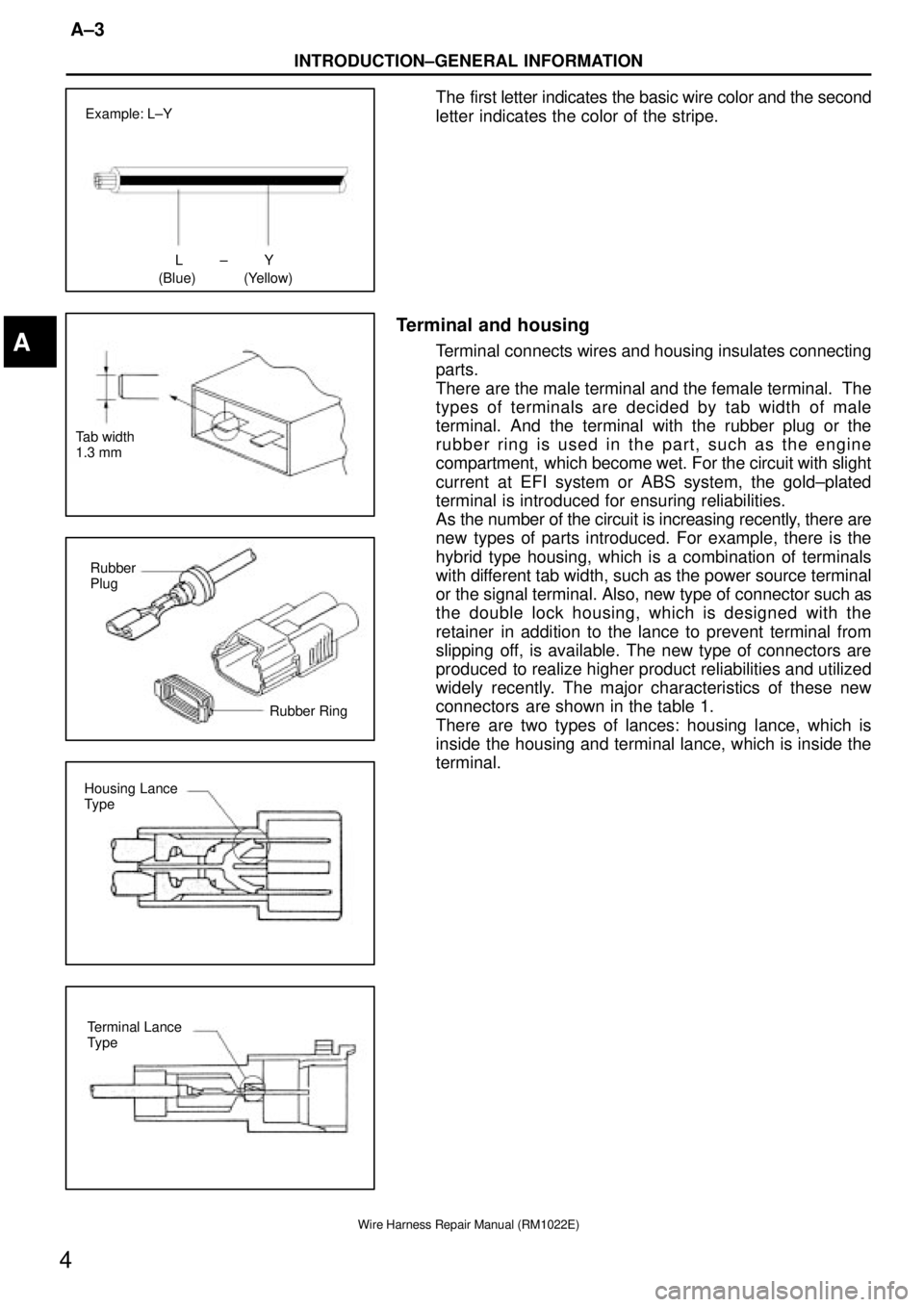
LY±
(Blue) (Yellow) Example: L±Y
Tab width
1.3 mm
Rubber
Plug
Rubber Ring
Housing Lance
Type
Terminal Lance
Type
INTRODUCTION±GENERAL INFORMATION
A±3
4
Wire Harness Repair Manual (RM1022E)
The first letter indicates the basic wire color and the second
letter indicates the color of the stripe.
Terminal and housing
Terminal connects wires and housing insulates connecting
parts.
There are the male terminal and the female terminal. The
types of terminals are decided by tab width of male
terminal. And the terminal with the rubber plug or the
rubber ring is used in the part, such as the engine
compartment, which become wet. For the circuit with slight
current at EFI system or ABS system, the gold±plated
terminal is introduced for ensuring reliabilities.
As the number of the circuit is increasing recently, there are
new types of parts introduced. For example, there is the
hybrid type housing, which is a combination of terminals
with different tab width, such as the power source terminal
or the signal terminal. Also, new type of connector such as
the double lock housing, which is designed with the
retainer in addition to the lance to prevent terminal from
slipping off, is available. The new type of connectors are
produced to realize higher product reliabilities and utilized
widely recently. The major characteristics of these new
connectors are shown in the table 1.
There are two types of lances: housing lance, which is
inside the housing and terminal lance, which is inside the
terminal.A
Page 1430 of 2389
Reference:
(mm)
B±1
TERMINAL AND CONNECTOR REPAIR±PREPARATORY ITEMS
11
Wire Harness Repair Manual (RM1022E)
PREPARATORY ITEMS
Crimping tool AMP Part No. 169060For caulking
press sleeves
ToolSpecial tool Refer to the following illustrationTo remove the
terminal
SST 09991±00500
To remove the
0.64 connector
terminal
GaugeCaliper 0±150 mm
To measure the
diameter of the
core
Others
82999±12010 (Red)
Press sleeve 82999±12020 (Blue)
82999±12030 (Yellow)
To connect wires
Others
Silicon tape 08231±00045
To waterproof
the connected
section
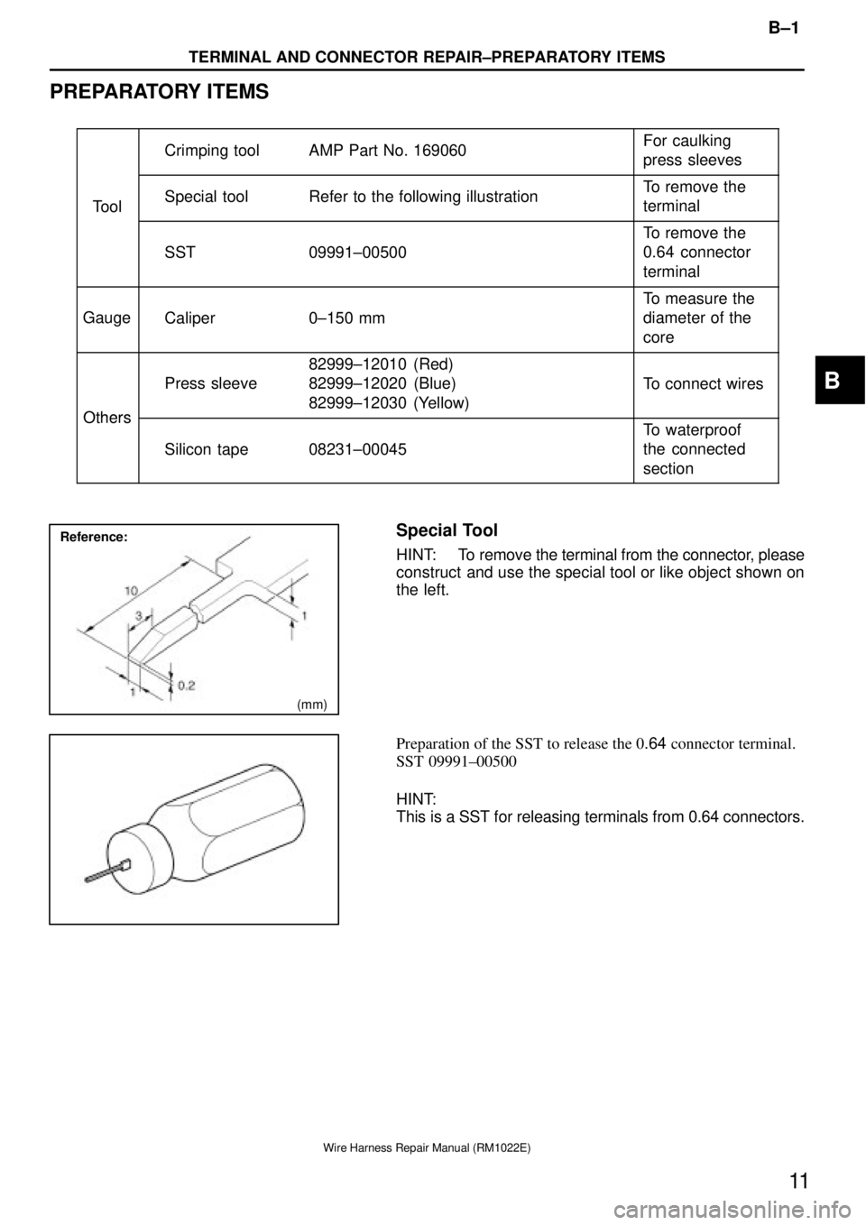
Special Tool
HINT: To remove the terminal from the connector, please
construct and use the special tool or like object shown on
the left.
Preparation of the SST to release the 0.64 connector terminal.
SST 09991±00500
HINT:
This is a SST for releasing terminals from 0.64 connectors.
B