Page 1226 of 2389
REMOVAL OF CYLINDER HEAD
(See page EM±48)
1. DISCONNECT CABLE FROM NEGATIVE TERMINAL
OF BATTERY
2. DRAIN ENGINE COOLANT (See page CO±4)
3. (A/T)
DISCONNECT THROTTLE CABLE AND BRACKET FROM
THROTTLE BODY
4. DISCONNECT ACCELERATOR CABLE AND BRACKET
FROM THROTTLE BODY AND AIR INTAKE CHAMBER
5. REMOVE CRUISE CONTROL ACTUATOR
(See step 9 on page EM±108)
6. REMOVE AIR CLEANER HOSE
7. REMOVE ALTERNATOR (See page CH±6)
8. REMOVE OIL PRESSURE SWITCH, ENGINE HANGERS
AND ALTERNATOR UPPER BRACKET
9. RAISE VEHICLE
NOTICE: Be sure the vehicle is securely supported.
10. REMOVE RH FRONT WHEEL
11. REMOVE ENGINE RH UNDER COVER
12. REMOVE SUSPENSION LOWER CROSSMEMBER
(See step 20 on page EM±109)
13. DISCONNECT FRONT EXHAUST PIPE FROM
CATALYTIC CONVERTER
(See step 25 on page EM±110)
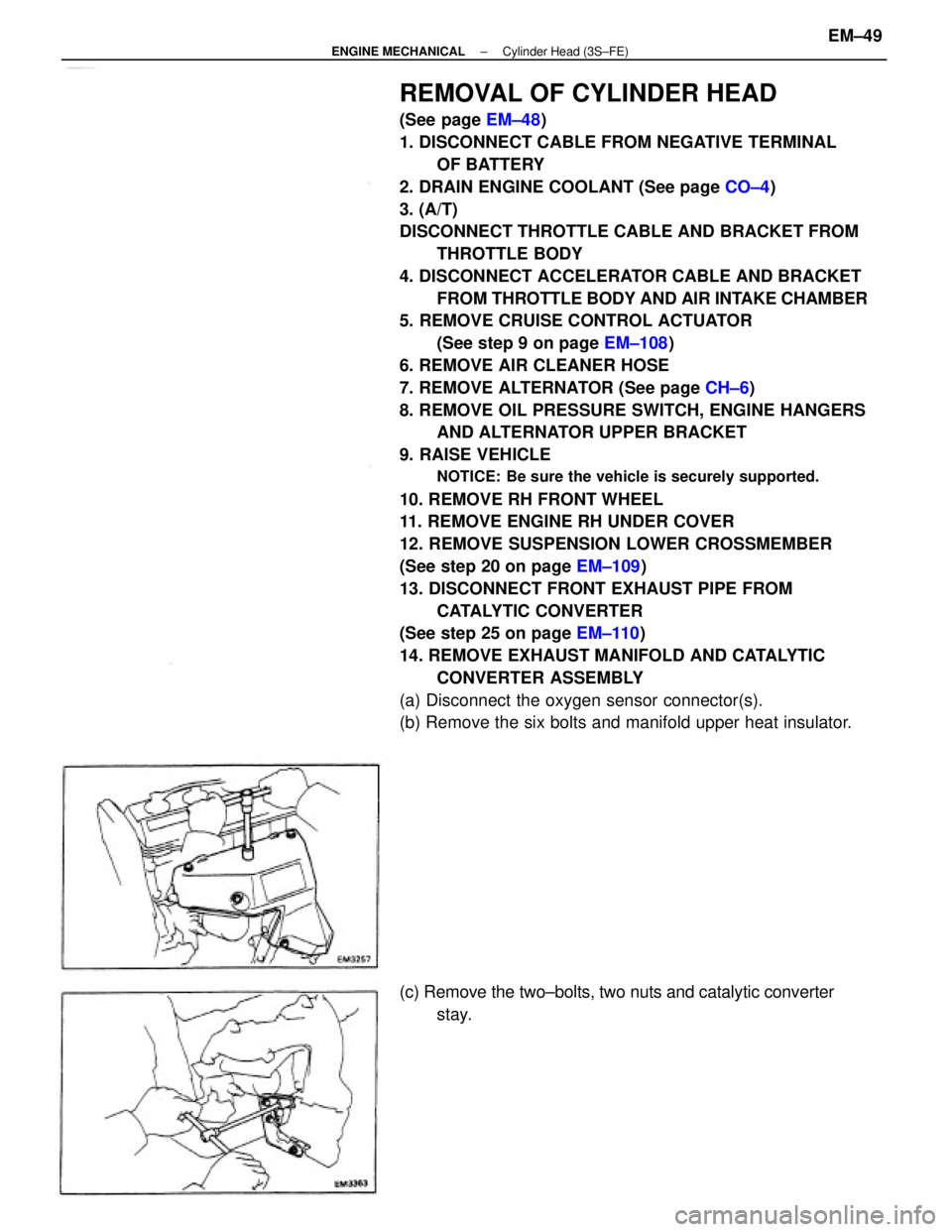
14. REMOVE EXHAUST MANIFOLD AND CATALYTIC
CONVERTER ASSEMBLY
(a) Disconnect the oxygen sensor connector(s).
(b) Remove the six bolts and manifold upper heat insulator.
(c) Remove the two±bolts, two nuts and catalytic converter
stay.
± ENGINE MECHANICALCylinder Head (3S±FE)EM±49
Page 1253 of 2389
REMOVAL OF CYLINDER HEADS
(See page EM±75)
1. DISCONNECT CABLE FROM NEGATIVE TERMINAL
OF BATTERY
2. DRAIN ENGINE COOLANT (See page CO±5)
3. (A/T)
DISCONNECT THROTTLE CABLE FROM THROTTLE
BODY
4. DISCONNECT ACCELERATOR CABLE FROM
THROTTLE BODY
5. (w/ CRUISE CONTROL SYSTEM)
REMOVE CRUISE CONTROL ACTUATOR AND
VACUUM PUMP (See step 74 on page EM±140)
6. REMOVE AIR CLEANER HOSE
(a) Disconnect the following hoses:
(1) RSC valve air hose
(2) Vacuum pipe hose
(b) Remove the air cleaner hose.
7. RAISE VEHICLE
NOTICE: Be sure the vehicle is securely supported.
8. REMOVE ENGINE RH UNDER COVER
9. REMOVE SUSPENSION LOWER CROSSMEMBER
(See step 26 on page EM±142)
10. REMOVE FRONT EXHAUST PIPE
(See step 27 on page EM±142)
11. REMOVE ALTERNATOR (See page CH±7)
12. REMOVE ISC VALVE
(See steps 2 to 4 on pages Fl±118 and 119)
13. REMOVE THROTTLE BODY
(See steps 5 to 6 on page FI±113)
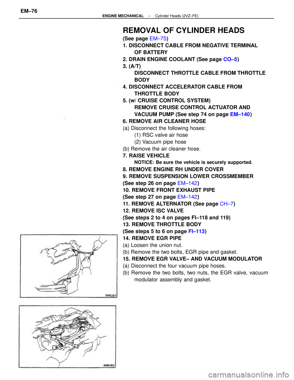
14. REMOVE EGR PIPE
(a) Loosen the union nut.
(b) Remove the two bolts, EGR pipe and gasket.
15. REMOVE EGR VALVE± AND VACUUM MODULATOR
(a) Disconnect the four vacuum pipe hoses.
(b) Remove the two bolts, two nuts, the EGR valve, vacuum
modulator assembly and gasket.
± ENGINE MECHANICALCylinder Heads (2VZ±FE)EM±76
Page 1359 of 2389
Replace tire or inflate tires to proper
pressure
Check front wheel alignment
Replace hub bearing
Tighten or replace suspension parts
Tighten or replace steering linkage
Adjust or repair steering gear
Replace tire or inflate tires to proper
pressure
Balance wheels
Replace shock absorber
Check front wheel alignment
Replace hub bearings
Inspect bail joints and bushings
Adjust or repair steering gear Wheels out of balance
Shock absorber worn out
Alignment incorrect
Hub bearings worn
Ball joints or bushings worn
Steering gear out of adjustment or broken Alignment incorrect
Hub bearing worn
Front or rear suspension parts loose or
broken
Steering linkage loosen or worn
Steering gear out of adjustment or broken
Inflate tires to proper pressure
Replace shock absorber
Check toe±in
Replace suspension parts Tires improperly inflated
Shock absorbers worn out
Alignment incorrect
Suspension parts wornInflate tires to proper pressure
Inspect stabilizer bar
Replace shock absorber Tires improperly inflated
Stabilizer bar bent or broken
Shock absorber worn outVehicle overloaded
Shock absorber worn out
Springs weakCheck loading
Replace shock absorber
Replace spring
FA±51
FA±3
FA±7
FA±56
SR±43,45.
48
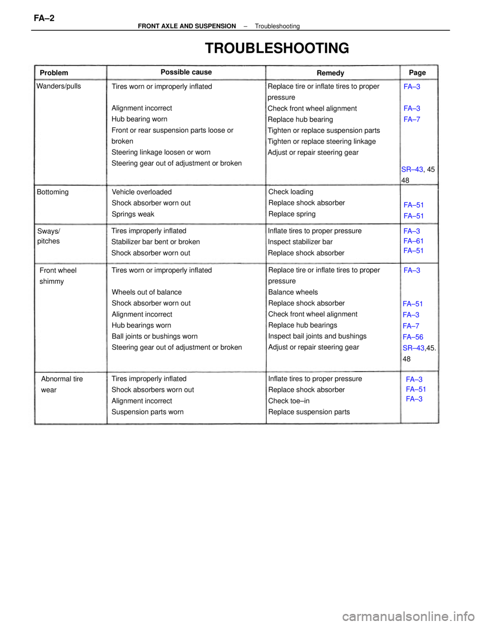
TROUBLESHOOTING
Tires worn or improperly inflatedTires worn or improperly inflated
Abnormal tire
wear Front wheel
shimmyFA±3
FA±61
FA±51
FA±3
FA±51
FA±3 SR±43, 45
48 Possible cause
Sways/
pitches Wanders/pulls
FA±51
FA±51 BottomingFA±3
FA±7 Problem
RemedyPage
FA±3
FA±3
± FRONT AXLE AND SUSPENSIONTroubleshootingFA ± 2
Page 1894 of 2389
1. REMOVE HOOD
2. RAISE VEHICLE
NOTICE: Be sure the vehicle is securely supported.
3. REMOVE ENGINE UNDER COVERS
4. DRAIN ENGINE OIL (See page LU±7)
5. REMOVE FRONT EXHAUST PIPE
(See step 25 on page EM±110)
6. REMOVE SUSPENSION LOWER CROSSMEMBER
7. REMOVE ENGINE MOUNTING CENTER MEMBER
OIL PUMP (3S±FE)
REMOVAL OF OIL PUMP
HINT: When repairing the oil pump, the oil pan and strainer
should be removed and cleaned.
± LUBRICATION SYSTEMOil Pump (3S±FE)LU±9
Page 1901 of 2389
1. REMOVE HOOD
2. RAISE VEHICLE
NOTICE: Be sure the vehicle is securely supported.
3. REMOVE ENGINE UNDER COVERS
4. DRAIN ENGINE OIL (See page LU±7)
5. REMOVE SUSPENSION LOWER CROSSMEMBER
(See step 26 on page EM±142)
6. REMOVE FRONT EXHAUST PIPE
(See step 27 on page EM±142)
7. REMOVE ENGINE MOUNTING CENTER MEMBER
(See step 31 on page EM±143)
8. REMOVE FRONT ENGINE MOUNTING INSULATOR
AND BRACKET
OIL PUMP (2VZ±FE)
REMOVAL OF OIL PUMP
HINT: When repairing the oil pump, the oil pan and strainer
should be removed and cleaned.
± LUBRICATION SYSTEMOil Pump (2VZ±FE)LU±16
Page 1912 of 2389
Maintenance services indicated by a star (*) or asterisk (*) are required under the terms of the Emission Control Systems Warranty. See Owner's Guide or Warranty Booklet
for complete warranty information.
* For vehicles sold in California
* For vehicles sold outside California
(1) Applicable to vehicles operated under conditions of extensive idling and /or low speed driving for long distances such as police, taxi or door±to±door delivery use.
(2) Applicable when operating mainly on dusty roads. If not, follow SCHEDULE B.
(3) Includes inspection of fuel tank band and vapor vent system.
(4) Also applicable to lining drum for parking brake.
(5) Check for leakage.
(6) Check for oil leaks from steering gear housing.
(7) Applicable only when operating mainly on rough, muddy roads. The applicable parts are listed below. For other usage conditions, refer to SCHEDULE B.
w
Front and rear suspension member to body
w
0 Strut bar bracket to body bolts
w
Bolts for sheet installation
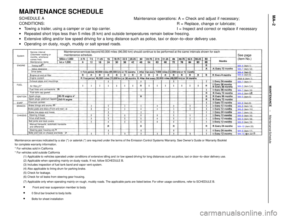
MAINTENANCE SCHEDULESCHEDULE A
CONDITIONS:
wTowing a trailer, using a camper or car top carrier.
wRepeated short trips less than 5 miles (8 km) and outside temperatures remain below freezing.
wExtensive idling and/or low speed driving for a long distance such as police, taxi or door±to±door delivery use.
wOperating on dusty, rough, muddy or salt spread roads.Maintenance operations: A = Check and adjust if necessary;
R = Replace, change or lubricate;
I = Inspect and correct or replace if necessary
Maintenance services beyond 60,000 miles (96,000 km) should continue to be performed at the same intervals shown for each
maintenance schedule.
Service interval
(Odometer reading or
months, whichever
comes first)
Maintenance items
Manual transaxle, automatic transaxle
and differential Brake pads and discs (Front and rear)
Bolts and nuts on chassis and bodyExhaust pipes and mountings
Steering gear housing oily Brake line pipes and hosesFuel lines and connections
Ball joints and dust coversEngine oil and oil filter
Spark plugs (platinum tipped)MA±4 (item 2)
MA±6 (item 6)
Brake linings and drumsFuel tank cap gasket
Drive shaft boots
MA±14 item 221 MA±10 (item 20) MA±5 (item 3,4)
Steering linkageMA±7 (item 12)
MA±8 (item 14) Valve clearance
MA±8 (item 16)
MA±9 (item 19) MA±7 (item 13) MA±7 (item 11
MA±7 (item 10)
MA±9 (item 18) Charcoal canister
MA±9 (item 17) MA±8 (item 151
See page
(item No.)
Engine coolant
MA±6 (item 9) MA±4 (item 1)
MA±4 (item 2)
MA±5 (item 5)
MA±8 (item 8) AAA±6 (item 7)
Air filter¿21*
Spark plugsTiming belt
Drive belts
IGNITION
CHASSIS BRAKESENGINESystem
EVAP FUEL
± MAINTENANCEMaintenance ScheduleMA±2
Page 1913 of 2389
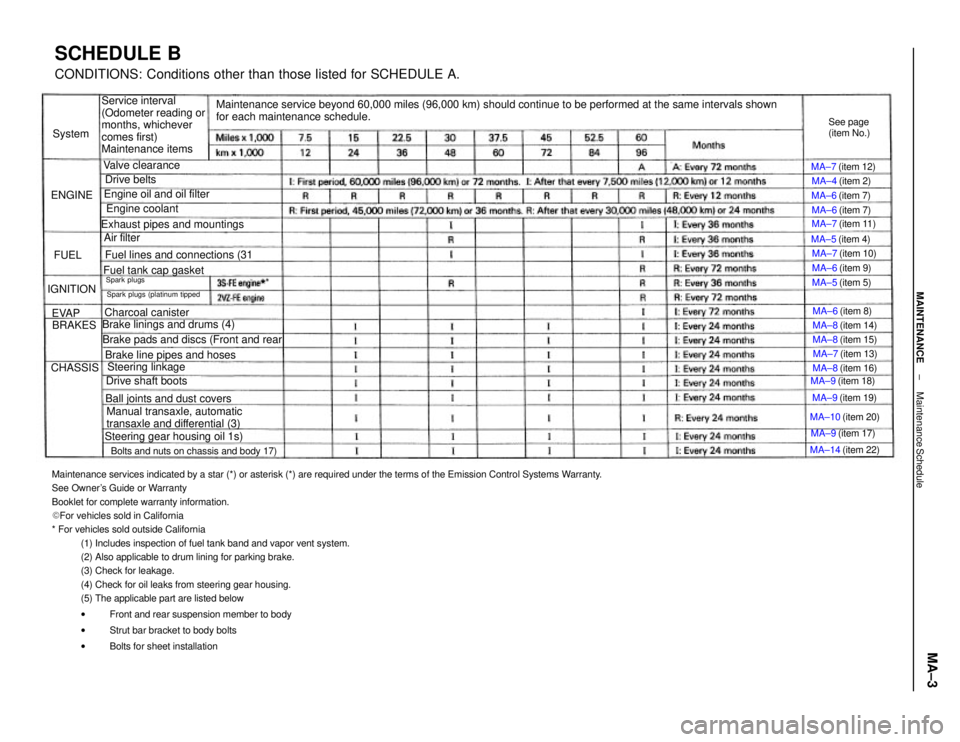
Maintenance services indicated by a star (*) or asterisk (*) are required under the terms of the Emission Control Systems Warranty.
See Owner's Guide or Warranty
Booklet for complete warranty information.
� For vehicles sold in California
* For vehicles sold outside California
(1) Includes inspection of fuel tank band and vapor vent system.
(2) Also applicable to drum lining for parking brake.
(3) Check for leakage.
(4) Check for oil leaks from steering gear housing.
(5) The applicable part are listed below
wFront and rear suspension member to body
wStrut bar bracket to body bolts
wBolts for sheet installation
Maintenance service beyond 60,000 miles (96,000 km) should continue to be performed at the same intervals shown
for each maintenance schedule.
SCHEDULE BCONDITIONS: Conditions other than those listed for SCHEDULE A.
Service interval
(Odometer reading or
months, whichever
comes first)
Maintenance items
Manual transaxle, automatic
transaxle and differential (3) Brake pads and discs (Front and rearBolts and nuts on chassis and body 17)Exhaust pipes and mountings
Steering gear housing oil 1s) Brake linings and drums (4)
Brake line pipes and hoses Fuel lines and connections (31
Ball joints and dust covers Engine oil and oil filterSpark plugs (platinum tippedFuel tank cap gasket
MA±14 (item 22) MA±10 (item 20)
Charcoal canister
Steering linkage
Drive shaft boots
MA±7 (item 11)
MA±9 (item 19) MA±9 (item 18) MA±7 (item 13) MA±7 (item 10)
MA±8 (item 14) MA±7 (item 12)
MA±8 (item 16) MA±8 (item 15) See page
(item No.)
Engine coolant
MA±9 (item 17)
Valve clearance
MA±6 (item 8) MA±4 (item 2)
MA±6 (item 9) MA±6 (item 7)
MA±6 (item 7)
MA±5 (item 5) MA±5 (item 4)
Drive belts
Air filterSpark plugs
IGNITION
CHASSISBRAKES ENGINESystem
EVAPFUEL
± MAINTENANCEMaintenance ScheduleMA±3
Page 2173 of 2389
2. DISCONNECT PROPELLER SHAFT
(a) Place the matchmarks on the both flanges.
(b) Remove the four bolts, washers and nuts.
(c) Disconnect the propeller shaft from the differential.
REPLACEMENT OF FRONT OIL SEAL
1. REMOVE REAR CROSSMEMBER
DIFFERENTIAL
On±Vehicle Repair
± REAR AXLE AND SUSPENSIONDifferential (4WD)RA±27