Page 247 of 2389

4. INSTALL GROMMETS ON INLET AND OUTLET
FITTINGS
5. CONNECT LIQUID TUBE TO COOLING UNIT INLET
FITTING
Torque the nut.
Torque: 140 kg±cm (10 ft±Ib, 14 N±m)
6. CONNECT SUCTION TUBE TO COOLING UNIT
OUTLET FITTING
Torque the nut.
Torque: 330 kg±cm (24 ft±ib, 32 N±m)
7. IF EVAPORATOR WAS REPLACED, ADD
COMPRESSOR OIL TO COMPRESSOR
Add 40 ± 50 cc (1.4 ± 1.7 fl.oz.)
Compressor oil: DENSOOIL 6,
SUNISO NO. 5GS or equivalent
8. CONNECT NEGATIVE CABLE TO BATTERY
9. EVACUATE AIR FROM AIR CONDITIONING SYSTEM
10. CHARGE AIR CONDITIONING SYSTEM WITH
REFRIGERANT AND CHECK FOR GAS LEAKAGE
Specified amount: 600 ± 700 g (1.3 ± 1.7 Ib)
REFRIGERANT LINES
(See page AC±12)
1. INSPECT HOSES AND TUBES FOR LEAKAGE
Use a gas leak detector. Replace, if necessary.
2. CHECK THAT HOSE AND TUBE CLAMPS ARE NOT
LOOSE
Tighten or replace as necessary.
REPLACEMENT OF REFRIGERANT
LINES
1. DISCHARGE REFRIGERATION SYSTEM
2. REPLACE FAULTY TUBE OR HOSE
HINT: Cap the open fitting immediately to keep moisture
out of the system.
3. TIGHTENING TORQUE FOR O±RING AND BOLTED
TYPE FITTINGS
(See page AC±12)
4. EVACUATE AIR FROM AIR CONDITIONING SYSTEM
5. CHARGE AIR CONDITIONING SYSTEM WITH
REFRIGERANT AND CHECK FOR GAS LEAKAGE
Specified amount: 600 ± 750 g (1.3 ± 1.7 Ib)
± AIR CONDITIONING SYSTEMCooling UnitAC±42
Page 248 of 2389

4. INSTALL GROMMETS ON INLET AND OUTLET
FITTINGS
5. CONNECT LIQUID TUBE TO COOLING UNIT INLET
FITTING
Torque the nut.
Torque: 140 kg±cm (10 ft±Ib, 14 N±m)
6. CONNECT SUCTION TUBE TO COOLING UNIT
OUTLET FITTING
Torque the nut.
Torque: 330 kg±cm (24 ft±lb, 32 N±m)
7. IF EVAPORATOR WAS REPLACED, ADD
COMPRESSOR OIL TO COMPRESSOR
Add 40 ± 50 cc (1.4 ± 1.7 fl.oz.)
Compressor oil: DENSOOIL 6,
SUNISO NO. 5GS or equivalent
8. CONNECT NEGATIVE CABLE TO BATTERY
9. EVACUATE AIR FROM AIR CONDITIONING SYSTEM
10. CHARGE AIR CONDITIONING SYSTEM WITH
REFRIGERANT AND CHECK FOR GAS LEAKAGE
Specified amount: 600 ± 700 g (1.3 ± 1.7 Ib)
REFRIGERANT LINES
(See page AC±12)
1. INSPECT HOSES AND TUBES FOR LEAKAGE
Use a gas leak detector. Replace, if necessary.
2. CHECK THAT HOSE AND TUBE CLAMPS ARE NOT
LOOSE
Tighten or replace as necessary.
REPLACEMENT OF REFRIGERANT
LINES
1. DISCHARGE REFRIGERATION SYSTEM
2. REPLACE FAULTY TUBE OR HOSE
HINT: Cap the open fitting immediately to keep moisture
out of the system.
3. TIGHTENING TORQUE FOR O±RING AND BOLTED
TYPE FITTINGS
(See page AC±12)
4. EVACUATE AIR FROM AIR CONDITIONING SYSTEM
5. CHARGE AIR CONDITIONING SYSTEM WITH
REFRIGERANT AND CHECK FOR GAS LEAKAGE
Specified amount: 600 ± 750 g (1.3 ± 1.7 Ib)
± AIR CONDITIONING SYSTEMRefrigerant LinesAC±42
Page 749 of 2389
RESET CIRCUIT BREAKER
1. REMOVE CIRCUIT BREAKER
(a) Disconnect the negative (±) cable from the battery.
(b) Remove the circuit breaker.
2. RESET CIRCUIT BREAKER
(a) Insert the needle into the reset hole and push it.
3. INSTALL CIRCUIT BREAKER
(a) Install the circuit breaker.
(b) Connect the negative (±) cable to the battery.
HINT: If a circuit breaker continues to cut out, a short circuit
is indicated. Have the system checked by a qualified tec
nician.
REPLACEMENT OF FUSE AND
FUSIBLE LINK
HINT: If replacing the fuse or fusible link, be sure to
replace it with a fuse or fusible link with an equal amperage
rating.(b) Using an ohmmeter, check that there is continuity be-
tween both terminals of the circuit breaker.
If continuity is not as specified, replace the circuit breaker.
HINT: If replacing the circuit breaker, be sure to replace
it with a breaker with an equal amperage, rating.
± BODY ELECTRICAL SYSTEMGeneral InformationBE±3
Page 774 of 2389

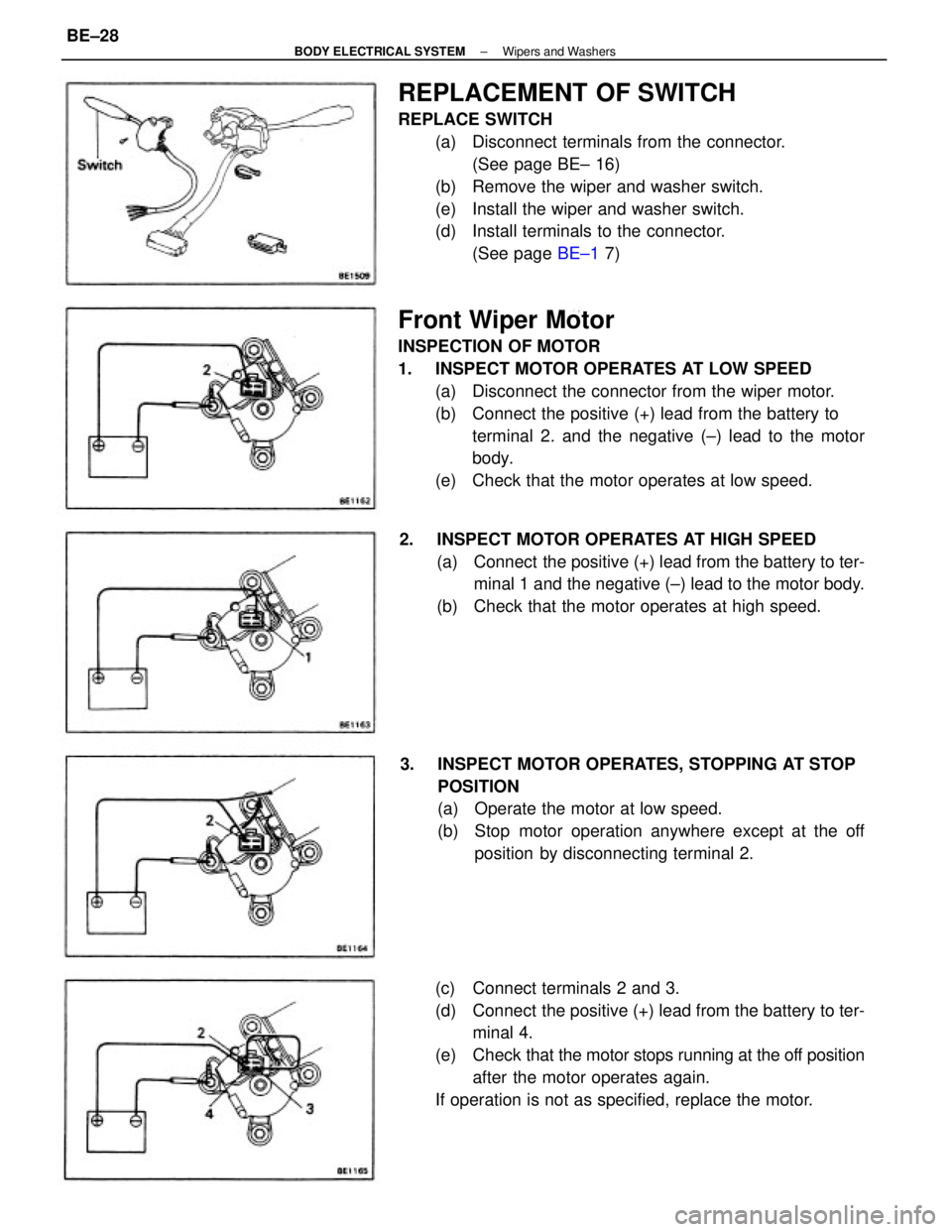
Front Wiper Motor
INSPECTION OF MOTOR
1. INSPECT MOTOR OPERATES AT LOW SPEED
(a) Disconnect the connector from the wiper motor.
(b) Connect the positive (+) lead from the battery to
terminal 2. and the negative (±) lead to the motor
body.
(e) Check that the motor operates at low speed.
REPLACEMENT OF SWITCH
REPLACE SWITCH
(a) Disconnect terminals from the connector.
(See page BE± 16)
(b) Remove the wiper and washer switch.
(e) Install the wiper and washer switch.
(d) Install terminals to the connector.
(See page BE±1 7)
(c) Connect terminals 2 and 3.
(d) Connect the positive (+) lead from the battery to ter-
minal 4.
(e) Check that the motor stops running at the off position
after the motor operates again.
If operation is not as specified, replace the motor. 3. INSPECT MOTOR OPERATES, STOPPING AT STOP
POSITION
(a) Operate the motor at low speed.
(b) Stop motor operation anywhere except at the off
position by disconnecting terminal 2. 2. INSPECT MOTOR OPERATES AT HIGH SPEED
(a) Connect the positive (+) lead from the battery to ter-
minal 1 and the negative (±) lead to the motor body.
(b) Check that the motor operates at high speed.
± BODY ELECTRICAL SYSTEMWipers and WashersBE±28