Page 1036 of 2389
DIAGNOSIS SYSTEM
DESCRIPTION
The ECU contains a built±in, self±diagnosis system which de-
tects troubles within the engine signal network and then flashed
a
warning on the ºCHECKº engine warning light on the instrument
panel flashes.
By analyzing various signals shown in the tables (See pages FI±
25 or 27) the ECU detects system malfunctions which are re-
lated to the various operating parameter sensors or actuator.
The ECU
stores the failure code associated with the detected failure until
the diagnosis system is cleared by removing the EFI fuse with
the ignition switch OFF.
A ºCHECKº engine warning light on the instrument panel informs
the driver that a malfunction has been detected.
The light goes oft automatically when the malfunction has been
cleared.
OUTPUT OF DIAGNOSTIC CODES
To obtain an output of diagnostic codes, proceed as follow:
1. Initial conditions
(a) Battery voltage 11 V or more
(b) Throttle valve fully closed (throttle position sensor IDL
points closed)
(e) Transmission in neutral position
(d) Accessories switched OFF
(e) Engine at normal operating temperature
2. Turn the ignition switch to ON. Do not start the engine.
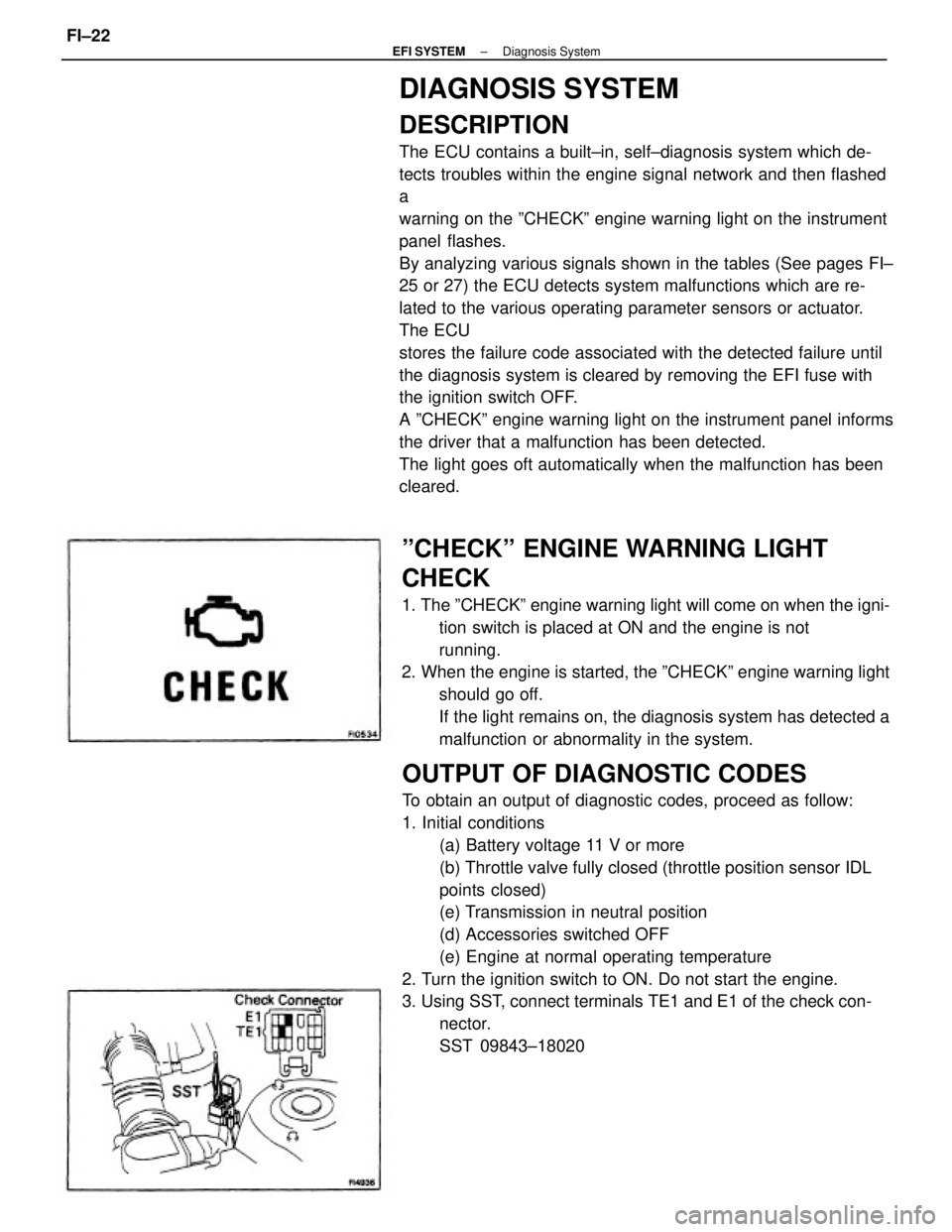
3. Using SST, connect terminals TE1 and E1 of the check con-
nector.
SST 09843±18020
ºCHECKº ENGINE WARNING LIGHT
CHECK
1. The ºCHECKº engine warning light will come on when the igni-
tion switch is placed at ON and the engine is not
running.
2. When the engine is started, the ºCHECKº engine warning light
should go off.
If the light remains on, the diagnosis system has detected a
malfunction or abnormality in the system.
± EFI SYSTEMDiagnosis SystemFI±22
Page 1038 of 2389
CANCELLING DIAGNOSTIC CODE
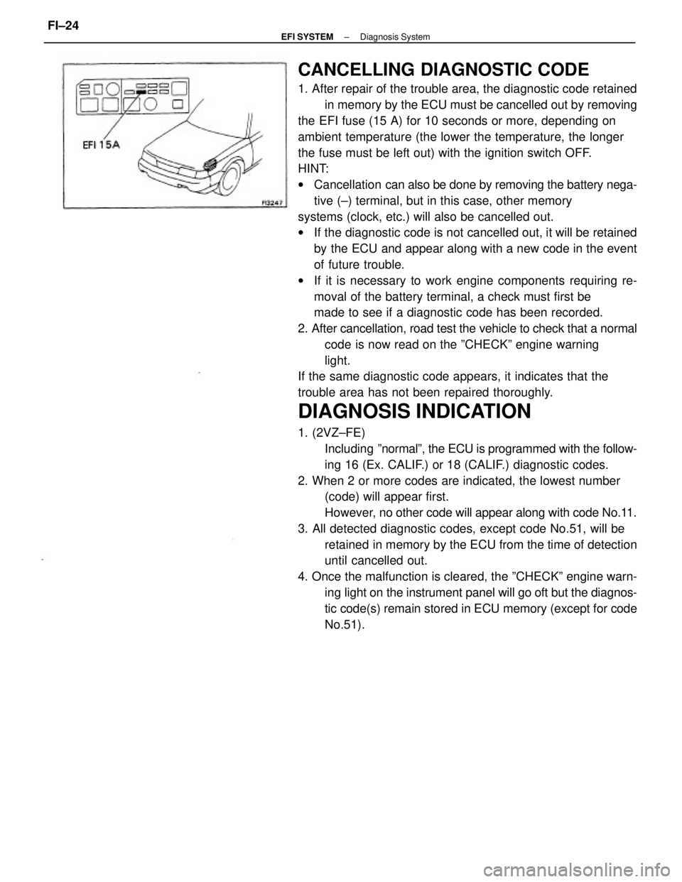
1. After repair of the trouble area, the diagnostic code retained
in memory by the ECU must be cancelled out by removing
the EFI fuse (15 A) for 10 seconds or more, depending on
ambient temperature (the lower the temperature, the longer
the fuse must be left out) with the ignition switch OFF.
HINT:
wCancellation can also be done by removing the battery nega-
tive (±) terminal, but in this case, other memory
systems (clock, etc.) will also be cancelled out.
wIf the diagnostic code is not cancelled out, it will be retained
by the ECU and appear along with a new code in the event
of future trouble.
wIf it is necessary to work engine components requiring re-
moval of the battery terminal, a check must first be
made to see if a diagnostic code has been recorded.
2. After cancellation, road test the vehicle to check that a normal
code is now read on the ºCHECKº engine warning
light.
If the same diagnostic code appears, it indicates that the
trouble area has not been repaired thoroughly.
DIAGNOSIS INDICATION
1. (2VZ±FE)
Including ºnormalº, the ECU is programmed with the follow-
ing 16 (Ex. CALIF.) or 18 (CALIF.) diagnostic codes.
2. When 2 or more codes are indicated, the lowest number
(code) will appear first.
However, no other code will appear along with code No.11.
3. All detected diagnostic codes, except code No.51, will be
retained in memory by the ECU from the time of detection
until cancelled out.
4. Once the malfunction is cleared, the ºCHECKº engine warn-
ing light on the instrument panel will go oft but the diagnos-
tic code(s) remain stored in ECU memory (except for code
No.51).
± EFI SYSTEMDiagnosis SystemFI±24
Page 1287 of 2389
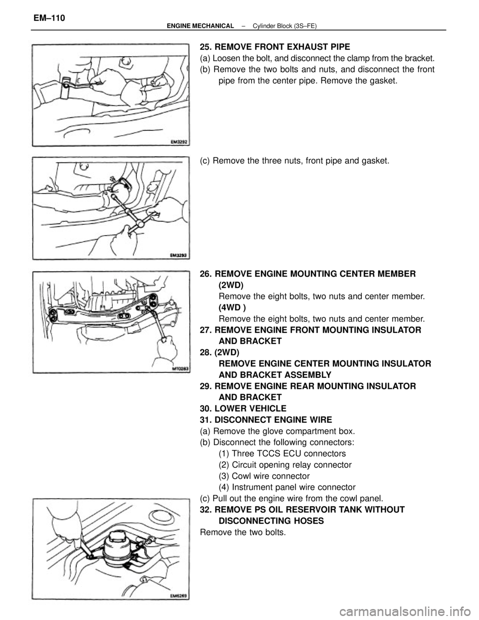
26. REMOVE ENGINE MOUNTING CENTER MEMBER
(2WD)
Remove the eight bolts, two nuts and center member.
(4WD )
Remove the eight bolts, two nuts and center member.
27. REMOVE ENGINE FRONT MOUNTING INSULATOR
AND BRACKET
28. (2WD)
REMOVE ENGINE CENTER MOUNTING INSULATOR
AND BRACKET ASSEMBLY
29. REMOVE ENGINE REAR MOUNTING INSULATOR
AND BRACKET
30. LOWER VEHICLE
31. DISCONNECT ENGINE WIRE
(a) Remove the glove compartment box.
(b) Disconnect the following connectors:
(1) Three TCCS ECU connectors
(2) Circuit opening relay connector
(3) Cowl wire connector
(4) Instrument panel wire connector
(c) Pull out the engine wire from the cowl panel.
32. REMOVE PS OIL RESERVOIR TANK WITHOUT
DISCONNECTING HOSES
Remove the two bolts. 25. REMOVE FRONT EXHAUST PIPE
(a) Loosen the bolt, and disconnect the clamp from the bracket.
(b) Remove the two bolts and nuts, and disconnect the front
pipe from the center pipe. Remove the gasket.
(c) Remove the three nuts, front pipe and gasket.
± ENGINE MECHANICALCylinder Block (3S±FE)EM±110
Page 1311 of 2389
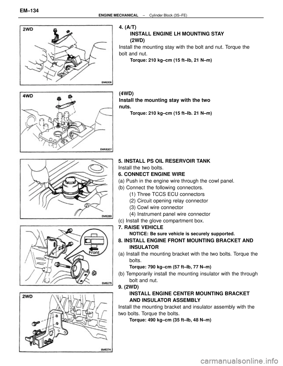
5. INSTALL PS OIL RESERVOIR TANK
Install the two bolts.
6. CONNECT ENGINE WIRE
(a) Push in the engine wire through the cowl panel.
(b) Connect the following connectors.
(1) Three TCCS ECU connectors
(2) Circuit opening relay connector
(3) Cowl wire connector
(4) Instrument panel wire connector
(c) Install the glove compartment box.
7. RAISE VEHICLE
NOTICE: Be sure vehicle is securely supported.
8. INSTALL ENGINE FRONT MOUNTING BRACKET AND
INSULATOR
(a) Install the mounting bracket with the two bolts. Torque the
bolts.
Torque: 790 kg±cm (57 ft±Ib, 77 N±m)
(b) Temporarily install the mounting insulator with the through
bolt and nut.
9. (2WD)
INSTALL ENGINE CENTER MOUNTING BRACKET
AND INSULATOR ASSEMBLY
Install the mounting bracket and insulator assembly with the
two bolts. Torque the bolts.
Torque: 490 kg±cm (35 ft±Ib, 48 N±m)
4. (A/T)
INSTALL ENGINE LH MOUNTING STAY
(2WD)
Install the mounting stay with the bolt and nut. Torque the
bolt and nut.
Torque: 210 kg±cm (15 ft±Ib, 21 N±m)
(4WD)
Install the mounting stay with the two
nuts.
Torque: 210 kg±cm (15 ft±Ib. 21 N±m)
± ENGINE MECHANICALCylinder Block (3S±FE)EM±134
Page 1319 of 2389
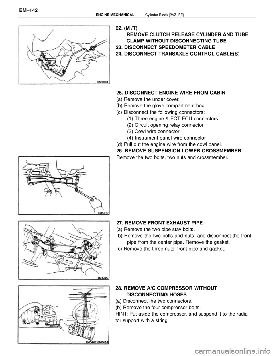
25. DISCONNECT ENGINE WIRE FROM CABIN
(a) Remove the under cover.
(b) Remove the glove compartment box.
(c) Disconnect the following connectors:
(1) Three engine & ECT ECU connectors
(2) Circuit opening relay connector
(3) Cowl wire connector
(4) Instrument panel wire connector
(d) Pull out the engine wire from the cowl panel.
26. REMOVE SUSPENSION LOWER CROSSMEMBER
Remove the two bolts, two nuts and crossmember.
28. REMOVE A/C COMPRESSOR WITHOUT
DISCONNECTING HOSES
(a) Disconnect the two connectors.
(b) Remove the four compressor bolts.
HINT: Put aside the compressor, and suspend it to the radia-
tor support with a string.22. (M /T)
REMOVE CLUTCH RELEASE CYLINDER AND TUBE
CLAMP WITHOUT DISCONNECTING TUBE
23. DISCONNECT SPEEDOMETER CABLE
24. DISCONNECT TRANSAXLE CONTROL CABLE(S)
27. REMOVE FRONT EXHAUST PIPE
(a) Remove the two pipe stay bolts.
(b) Remove the two bolts and nuts, and disconnect the front
pipe from the center pipe. Remove the gasket.
(c) Remove the three nuts, front pipe and gasket.
± ENGINE MECHANICALCylinder Block (2VZ±FE)EM±142
Page 1349 of 2389
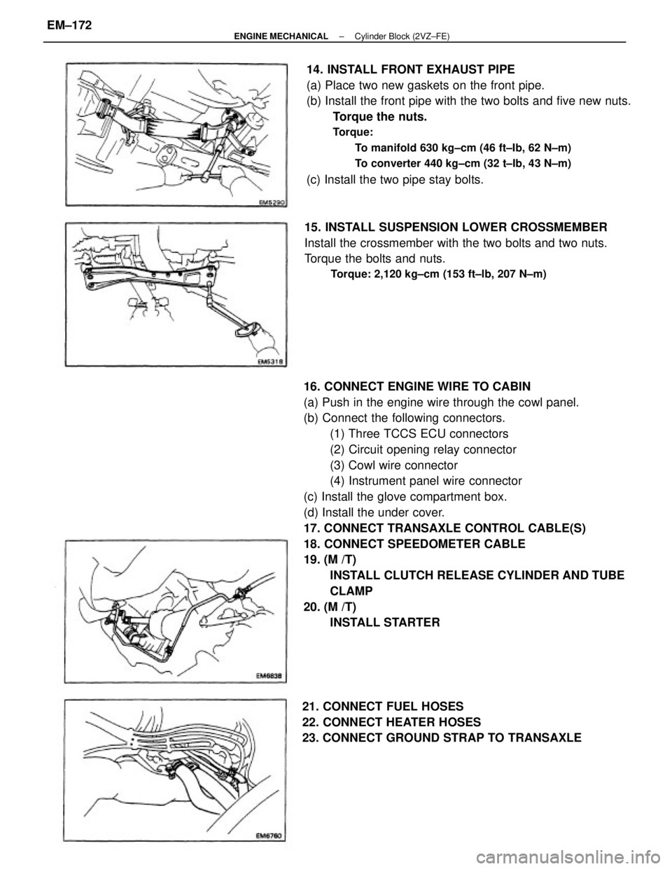
16. CONNECT ENGINE WIRE TO CABIN
(a) Push in the engine wire through the cowl panel.
(b) Connect the following connectors.
(1) Three TCCS ECU connectors
(2) Circuit opening relay connector
(3) Cowl wire connector
(4) Instrument panel wire connector
(c) Install the glove compartment box.
(d) Install the under cover.
17. CONNECT TRANSAXLE CONTROL CABLE(S)
18. CONNECT SPEEDOMETER CABLE
19. (M /T)
INSTALL CLUTCH RELEASE CYLINDER AND TUBE
CLAMP
20. (M /T)
INSTALL STARTER 14. INSTALL FRONT EXHAUST PIPE
(a) Place two new gaskets on the front pipe.
(b) Install the front pipe with the two bolts and five new nuts.
Torque the nuts.
Torque:
To manifold 630 kg±cm (46 ft±Ib, 62 N±m)
To converter 440 kg±cm (32 t±Ib, 43 N±m)
(c) Install the two pipe stay bolts.
15. INSTALL SUSPENSION LOWER CROSSMEMBER
Install the crossmember with the two bolts and two nuts.
Torque the bolts and nuts.
Torque: 2,120 kg±cm (153 ft±lb, 207 N±m)
21. CONNECT FUEL HOSES
22. CONNECT HEATER HOSES
23. CONNECT GROUND STRAP TO TRANSAXLE
± ENGINE MECHANICALCylinder Block (2VZ±FE)EM±172