Page 1927 of 2389

23. FINAL INSPECTION
(a) Check the operation of the body parts:
wHood
Auxiliary catch operation properly
Hood locks securely when closed
wFront and rear doors
Door locks operate properly
Doors close properly
wLuggage compartment door and back door
Door sock operates properly
wSeats
Seat adjusts easily and locks securely in any position
Front seat back locks securely in any position
Folding±down rear seat backs lock securely
(b) Road test
wCheck the engine and chassis for abnormal noises.
wCheck that the vehicle does not wander or pull to one side.
wCheck that the brakes work properly and do not drag.
wPerform bedding down of the parking brake shoes and drum.
(See page MA±8)
(c) Be sure to deliver a clean car especially check:
wSteering wheel
wShift lever knob
wAll switch knobs
wDoor handles
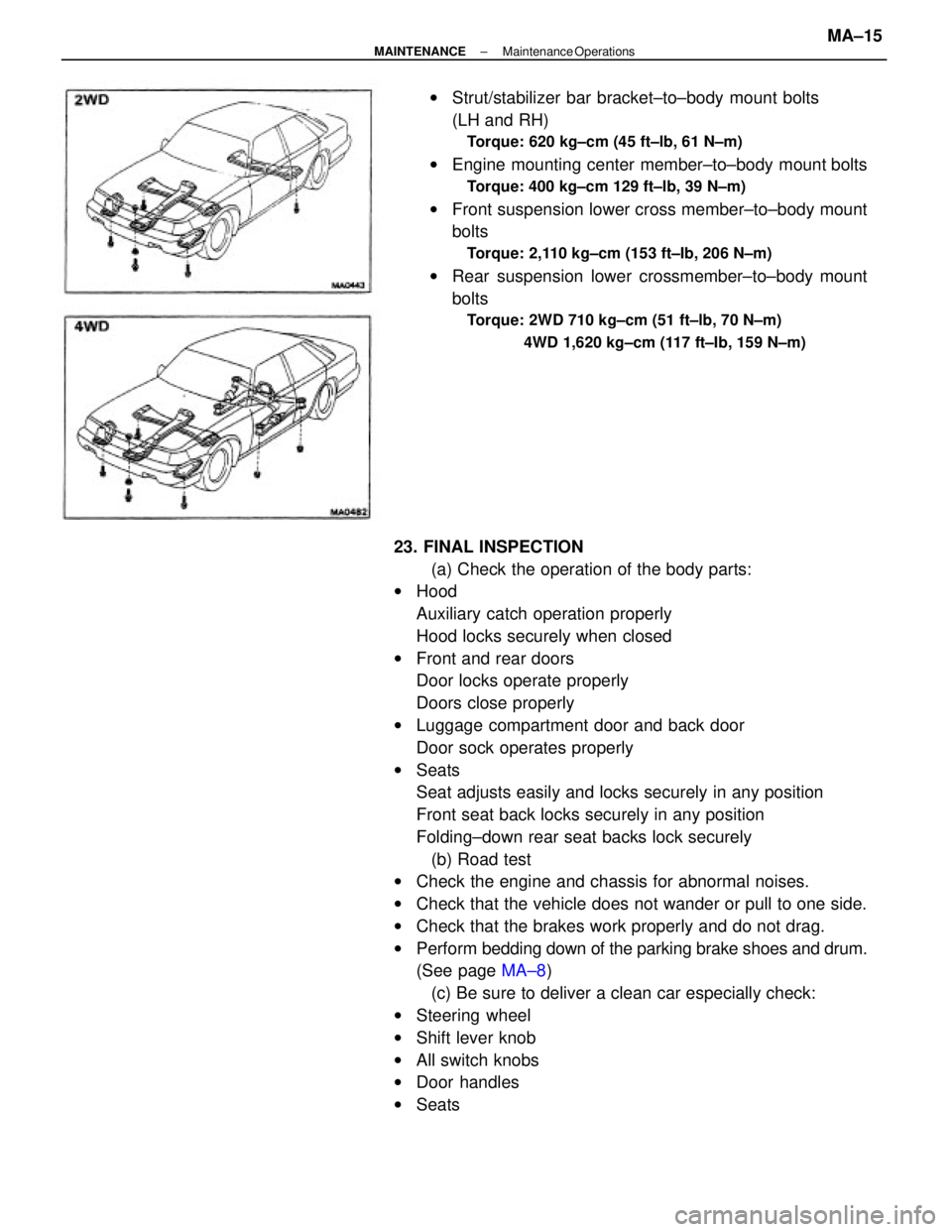
wSeatswStrut/stabilizer bar bracket±to±body mount bolts
(LH and RH)
Torque: 620 kg±cm (45 ft±lb, 61 N±m)
wEngine mounting center member±to±body mount bolts
Torque: 400 kg±cm 129 ft±lb, 39 N±m)
wFront suspension lower cross member±to±body mount
bolts
Torque: 2,110 kg±cm (153 ft±Ib, 206 N±m)
wRear suspension lower crossmember±to±body mount
bolts
Torque: 2WD 710 kg±cm (51 ft±lb, 70 N±m)
4WD 1,620 kg±cm (117 ft±Ib, 159 N±m)
± MAINTENANCEMaintenance OperationsMA±15
Page 1990 of 2389
22. REMOVE STRAIGHT SCREW, LOCKING BALLS AND
SPRINGS
(a) Using SST, remove the two plugs.
SST 09313±30021
(b) Using a magnetic finger, remove the two spring seats,
springs and balls.
26. REMOVE NO.2 SHIFT FORK SHAFT, SHIFT HEAD AND
NO.1 SHIFT FORK
(a) Pull out the No.2shift fork shaft.
(b) Remove the shift head and No.1 shift fork. 25. REMOVE INTERLOCK ROLLER
Using a magnetic finger, remove the interlock roller from
the reverse shift fork. 24. REMOVE NO.1 SHIFT FORK SHAFT
Pull up No.3 shift fork shaft, remove the No.1 shift fork
shaft. 23. REMOVE SET BOLT
± MANUAL TRANSAXLERemoval of Component PartsMT±55
Page 2033 of 2389
13. INSTALL LOCKING BALLS, SPRINGS, SEATS AND
PLUGS
(a) Install the two locking balls, springs and seats.
(b)Apply sealant to the two plugs.
Sealant: Part No.08833±00080, THREE BOND 1344,
LOCTITE 242 or equivalent
(c) Using SST, install and torque two plugs.
SST 09313±30021
Torque: 250 kg±cm (18 ft±lb, 25 N±m)
15. INSTALL REVERSE SHIFT ARM BRACKET AND NO.2
OIL PIPE
(a) Put the reverse shift fork pivot into the reverse shift arm
and install the reverse shift arm bracket to the trans-
axle case.
(b) Install the bolt. 12. INSTALL SET BOLTS
Install and torque the three set bolts.
Torque: 240 kg±cm I17 ft±Ib, 24 N±m)o
14. INSTALL REVERSE IDLER GEAR AND SHAFT
Install the reverse idler gear and shaft as shown.
± MANUAL TRANSAXLEComponent PartsMT±101
Page 2068 of 2389
24. REMOVE REVERSE IDLER GEAR, THRUST WASHER
AND SHAFT
Pull out the shaft, remove the reverse idler gear and
thrust washer.
25. REMOVE PLUGS, SEATS, SPRINGS AND BALLS
(a) Using SST, remove the two plugs.
SST 09313±30021
27. REMOVE NO±1 SHIFT FORK SHAFT
Pull up No.3 shift fork shaft, remove the No.1 shift fork
shaft. (b) Using a magnetic finger, remove the two seats,
springs and balls.
26. REMOVE SET BOLTS
Remove the three set bolts.
± MANUAL TRANSAXLERemoval of Component PartsMT±127
Page 2104 of 2389
11. INSTALL NO.1 SHIFT FORK SHAFT
(a) Using a magnetic finger, install the interlock roller into
the reverse shift fork.
HINT: Align the groove of No.1 fork shaft with the inter-
lock roller hole of reverse shift fork.
(b) Install the No±1 shift fork shaft to the case,
through the No. 1 shift fork and reverse shift
fork.
HINT: If it is difficult to put the No.1 shift fork shaft
through the reverse shift fork, pull up the No.3 shift
fork shaft.
13. INSTALL LOCKING BALLS, SPRINGS, SPRING SEATS
AND SCREW PLUGS
(a) Install the two locking balls, springs and spring
seats.(c) Install the No.2 shift fork shaft to the case,
through the No.2 shift fork, the shift head and
the No. t shift fork.
12. INSTALL SET BOLTS
Install and torque the three bolts.
Torque: 240 kg±cm (17 ft±lb, 24 N±m)
± MANUAL TRANSAXLEInstallation of Component PartsMT±195
Page 2389 of 2389
17. INSTALL TIE ROD ENDS
(a) Screw the lock nuts and tie rod ends onto the rack
ends until the matchmarks are aligned.
(b) After adjusting toe±in, torque the lock nuts.
Torque: 570 kg±cm (41 ft±Ib, 56 N±m)
(b) Using SST, install and torque the tubes.
SST 09633±00020
Torque: 200 kg±cm (14 ft±Ib, 20 N±m)
HINT: Use a torque wrench with a fulcrum length of 300
mm (11.81 in.). 18. INSTALL RIGHT AND LEFT TURN PRESSURE TUBES
(a) Install new union seats as shown.
± STEERINGPower Steering (Gear Housing)SR±63