1986 TOYOTA CAMRY V20 oil temperature
[x] Cancel search: oil temperaturePage 1849 of 2389
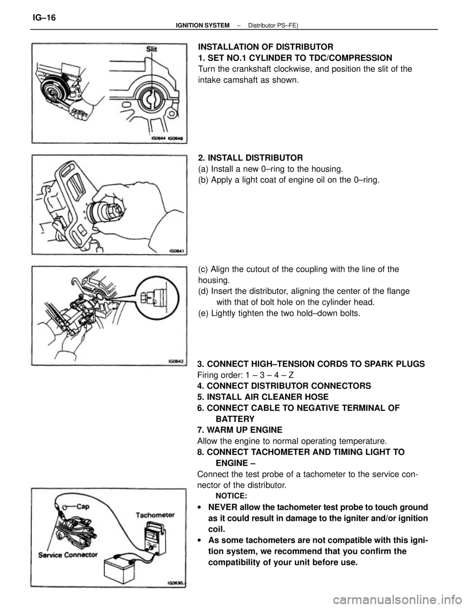
3. CONNECT HIGH±TENSION CORDS TO SPARK PLUGS
Firing order: 1 ± 3 ± 4 ± Z
4. CONNECT DISTRIBUTOR CONNECTORS
5. INSTALL AIR CLEANER HOSE
6. CONNECT CABLE TO NEGATIVE TERMINAL OF
BATTERY
7. WARM UP ENGINE
Allow the engine to normal operating temperature.
8. CONNECT TACHOMETER AND TIMING LIGHT TO
ENGINE ±
Connect the test probe of a tachometer to the service con-
nector of the distributor.
NOTICE:
wNEVER allow the tachometer test probe to touch ground
as it could result in damage to the igniter and/or ignition
coil.
wAs some tachometers are not compatible with this igni-
tion system, we recommend that you confirm the
compatibility of your unit before use. (c) Align the cutout of the coupling with the line of the
housing.
(d) Insert the distributor, aligning the center of the flange
with that of bolt hole on the cylinder head.
(e) Lightly tighten the two hold±down bolts. INSTALLATION OF DISTRIBUTOR
1. SET NO.1 CYLINDER TO TDC/COMPRESSION
Turn the crankshaft clockwise, and position the slit of the
intake camshaft as shown.
2. INSTALL DISTRIBUTOR
(a) Install a new 0±ring to the housing.
(b) Apply a light coat of engine oil on the 0±ring.
± IGNITION SYSTEMDistributor PS±FE)IG±16
Page 1854 of 2389
![TOYOTA CAMRY V20 1986 Service Information 6. WARM UP ENGINE
Allow the engine to normal operating temperature.
7. CONNECT TACHOMETER AND TIMING LIGHT TO
ENGINE
Connect the tachometer test probe to terminal IG [±] of the
check connector.
NOTIC TOYOTA CAMRY V20 1986 Service Information 6. WARM UP ENGINE
Allow the engine to normal operating temperature.
7. CONNECT TACHOMETER AND TIMING LIGHT TO
ENGINE
Connect the tachometer test probe to terminal IG [±] of the
check connector.
NOTIC](/manual-img/14/57449/w960_57449-1853.png)
6. WARM UP ENGINE
Allow the engine to normal operating temperature.
7. CONNECT TACHOMETER AND TIMING LIGHT TO
ENGINE
Connect the tachometer test probe to terminal IG [±] of the
check connector.
NOTICE:
wNEVER allow the tachometer test probe to touch ground
as it could result in damage to the igniter
and/or ignition coil.
wAs some tachometers are not compatible with this igni-
tion system, we recommended that you confirm the
compatibility of your unit before use.
8. ADJUST IGNITION TIMING
(a) Check the idle speed.
Idle speed: 700
+ 50 rpm
(b) Using SST connect terminals TE1 and E1 of the check con-
nector.
SST 09843±18020
(c) Using a timing light, check the ignition timing.
Ignition timing: 10°6TDC @ idle
(Transmission in N range)
(d) Loosen the two hold±down bolts, and adjust by turning the
distributor.
(e) Tighten the hold±down bolts, and recheck the ignition timing.
Torque: 185 kg±cm (13 ft±Ib, 18 N±m)
9. FURTHER CHECK IGNITION TIMING
Ignition timing: 10°BTDC @ idle
(Transmission in N range)
HINT: The timing mark moves in a range between 13°
and 27°.
10. DISCONNECT TACHOMETER AND TIMING LIGHT
FROM ENGINE (f) Remove SST.
SST 09843±18020
± IGNITION SYSTEMDistributor (2VZ±FE)IG±21
Page 1861 of 2389
PRECAUTIONS FOR VEHICLES EQUIPPED WITH A
CATALYTIC CONVERTER
CAUTION: If large amounts of unburned gasoline flow into the converter, it may overheat
and create a fire hazard. To prevent this, observe the following precautions and
explain them to your customer.
1. Use only unleaded gasoline.
2. Avoid prolonged idling.
Avoid running the engine at idle speed for more than 20
minutes.
3. Avoid spark jump test.
(a) Spark jump test only when absolutely necessary. Perform this test as rapidly as pos-
sible.
(b) While testing, never race the engine.
4. Avoid prolonged engine compression measurement.
Engine compression tests must be made as rapidly as possible.
5. Do not run engine when fuel tank is nearly empty.
This may cause the engine to misfire and create an extra
load on the converter.
6. Avoid coasting with ignition turned off and prolonged braking.
7. Do not dispose of used catalyst along with parts contaminated with gasoline or oil.(f) When steam cleaning an engine, protect the distribu-
tor, air filter and VCV from water.
(g) Never use an impact wrench to remove or install tem-
perature switches or temperature sensors.
(h) When checking continuity at the wire connector, insert
the tester probe carefully to prevent terminals from
bending.
(i) When using a vacuum gauge, never force the hose
onto a connector that is too large. Use a step±down
adapter instead. Once the hose has been stretched,
it may leak.
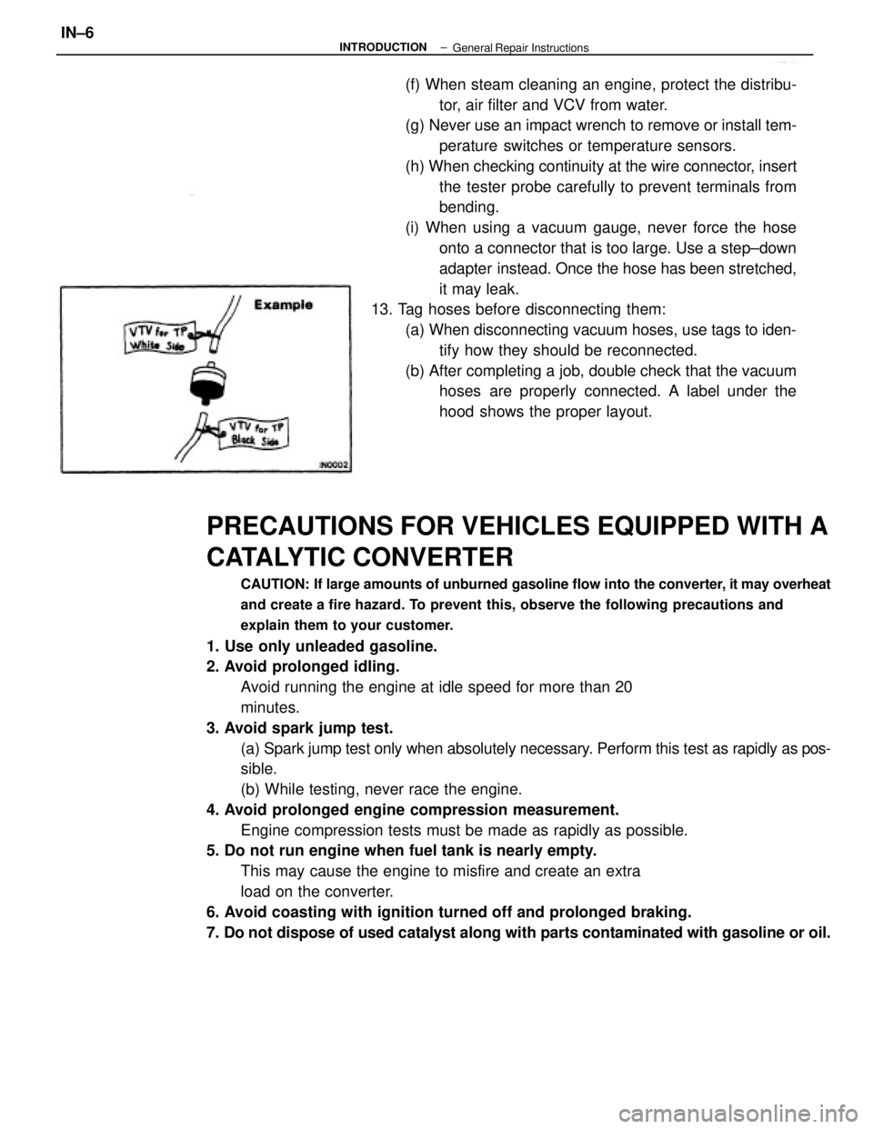
13. Tag hoses before disconnecting them:
(a) When disconnecting vacuum hoses, use tags to iden-
tify how they should be reconnected.
(b) After completing a job, double check that the vacuum
hoses are properly connected. A label under the
hood shows the proper layout.
± INTRODUCTIONIN±6General Repair Instructions
Page 1862 of 2389
PRECAUTIONS FOR VEHICLES EQUIPPED WITH A
CATALYTIC CONVERTER
CAUTION: If large amounts of unburned gasoline flow into the converter, it may overheat
and create a fire hazard. To prevent this, observe the following precautions and
explain them to your customer.
1. Use only unleaded gasoline.
2. Avoid prolonged idling.
Avoid running the engine at idle speed for more than 20
minutes.
3. Avoid spark jump test.
(a) Spark jump test only when absolutely necessary. Perform this test as rapidly as pos-
sible.
(b) While testing, never race the engine.
4. Avoid prolonged engine compression measurement.
Engine compression tests must be made as rapidly as possible.
5. Do not run engine when fuel tank is nearly empty.
This may cause the engine to misfire and create an extra
load on the converter.
6. Avoid coasting with ignition turned off and prolonged braking.
7. Do not dispose of used catalyst along with parts contaminated with gasoline or oil.(f) When steam cleaning an engine, protect the distribu-
tor, air filter and VCV from water.
(g) Never use an impact wrench to remove or install tem-
perature switches or temperature sensors.
(h) When checking continuity at the wire connector, insert
the tester probe carefully to prevent terminals from
bending.
(i) When using a vacuum gauge, never force the hose
onto a connector that is too large. Use a step±down
adapter instead. Once the hose has been stretched,
it may leak.
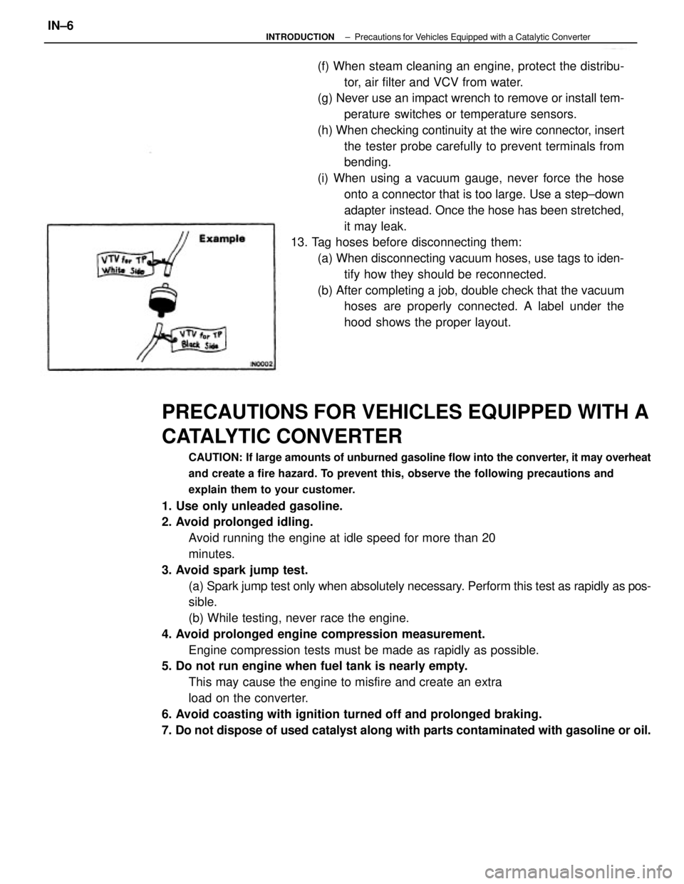
13. Tag hoses before disconnecting them:
(a) When disconnecting vacuum hoses, use tags to iden-
tify how they should be reconnected.
(b) After completing a job, double check that the vacuum
hoses are properly connected. A label under the
hood shows the proper layout.
± INTRODUCTIONPrecautions for Vehicles Equipped with a Catalytic ConverterIN±6
Page 1891 of 2389
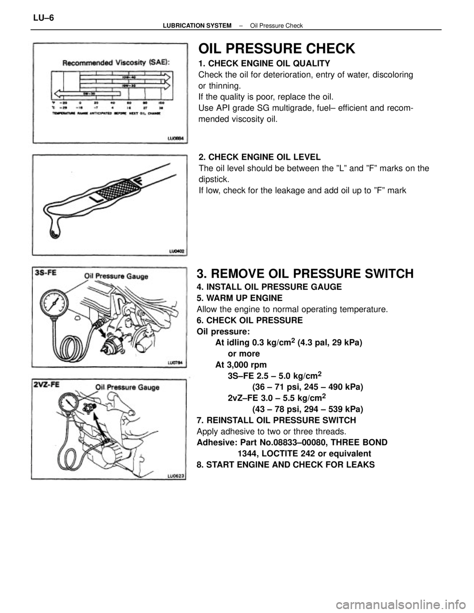
3. REMOVE OIL PRESSURE SWITCH
4. INSTALL OIL PRESSURE GAUGE
5. WARM UP ENGINE
Allow the engine to normal operating temperature.
6. CHECK OIL PRESSURE
Oil pressure:
At idling 0.3 kg/cm
2 (4.3 pal, 29 kPa)
or more
At 3,000 rpm
3S±FE 2.5 ± 5.0 kg/cm
2
(36 ± 71 psi, 245 ± 490 kPa)
2vZ±FE 3.0 ± 5.5 kg/cm
2
(43 ± 78 psi, 294 ± 539 kPa)
7. REINSTALL OIL PRESSURE SWITCH
Apply adhesive to two or three threads.
Adhesive: Part No.08833±00080, THREE BOND
1344, LOCTITE 242 or equivalent
8. START ENGINE AND CHECK FOR LEAKS
OIL PRESSURE CHECK
1. CHECK ENGINE OIL QUALITY
Check the oil for deterioration, entry of water, discoloring
or thinning.
If the quality is poor, replace the oil.
Use API grade SG multigrade, fuel± efficient and recom-
mended viscosity oil.
2. CHECK ENGINE OIL LEVEL
The oil level should be between the ºLº and ºFº marks on the
dipstick.
If low, check for the leakage and add oil up to ºFº mark
± LUBRICATION SYSTEMOil Pressure CheckLU±6
Page 1912 of 2389
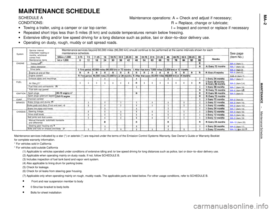
Maintenance services indicated by a star (*) or asterisk (*) are required under the terms of the Emission Control Systems Warranty. See Owner's Guide or Warranty Booklet
for complete warranty information.
* For vehicles sold in California
* For vehicles sold outside California
(1) Applicable to vehicles operated under conditions of extensive idling and /or low speed driving for long distances such as police, taxi or door±to±door delivery use.
(2) Applicable when operating mainly on dusty roads. If not, follow SCHEDULE B.
(3) Includes inspection of fuel tank band and vapor vent system.
(4) Also applicable to lining drum for parking brake.
(5) Check for leakage.
(6) Check for oil leaks from steering gear housing.
(7) Applicable only when operating mainly on rough, muddy roads. The applicable parts are listed below. For other usage conditions, refer to SCHEDULE B.
w
Front and rear suspension member to body
w
0 Strut bar bracket to body bolts
w
Bolts for sheet installation
MAINTENANCE SCHEDULESCHEDULE A
CONDITIONS:
wTowing a trailer, using a camper or car top carrier.
wRepeated short trips less than 5 miles (8 km) and outside temperatures remain below freezing.
wExtensive idling and/or low speed driving for a long distance such as police, taxi or door±to±door delivery use.
wOperating on dusty, rough, muddy or salt spread roads.Maintenance operations: A = Check and adjust if necessary;
R = Replace, change or lubricate;
I = Inspect and correct or replace if necessary
Maintenance services beyond 60,000 miles (96,000 km) should continue to be performed at the same intervals shown for each
maintenance schedule.
Service interval
(Odometer reading or
months, whichever
comes first)
Maintenance items
Manual transaxle, automatic transaxle
and differential Brake pads and discs (Front and rear)
Bolts and nuts on chassis and bodyExhaust pipes and mountings
Steering gear housing oily Brake line pipes and hosesFuel lines and connections
Ball joints and dust coversEngine oil and oil filter
Spark plugs (platinum tipped)MA±4 (item 2)
MA±6 (item 6)
Brake linings and drumsFuel tank cap gasket
Drive shaft boots
MA±14 item 221 MA±10 (item 20) MA±5 (item 3,4)
Steering linkageMA±7 (item 12)
MA±8 (item 14) Valve clearance
MA±8 (item 16)
MA±9 (item 19) MA±7 (item 13) MA±7 (item 11
MA±7 (item 10)
MA±9 (item 18) Charcoal canister
MA±9 (item 17) MA±8 (item 151
See page
(item No.)
Engine coolant
MA±6 (item 9) MA±4 (item 1)
MA±4 (item 2)
MA±5 (item 5)
MA±8 (item 8) AAA±6 (item 7)
Air filter¿21*
Spark plugsTiming belt
Drive belts
IGNITION
CHASSIS BRAKESENGINESystem
EVAP FUEL
± MAINTENANCEMaintenance ScheduleMA±2
Page 1915 of 2389
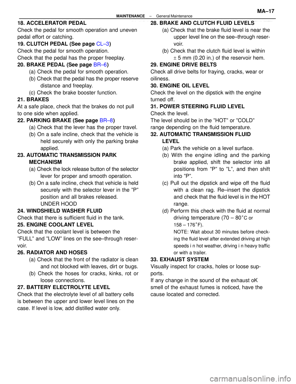
18. ACCELERATOR PEDAL
Check the pedal for smooth operation and uneven
pedal effort or catching.
19. CLUTCH PEDAL (See page CL±3)
Check the pedal for smooth operation.
Check that the pedal has the proper freeplay.
20. BRAKE PEDAL (See page BR±6)
(a) Check the pedal for smooth operation.
(b) Check that the pedal has the proper reserve
distance and freeplay.
(c) Check the brake booster function.
21. BRAKES
At a safe place, check that the brakes do not pull
to one side when applied.
22. PARKING BRAKE (See page BR±8)
(a) Check that the lever has the proper travel.
(b) On a safe incline, check that the vehicle is
held securely with only the parking brake
applied.
23. AUTOMATIC TRANSMISSION PARK
MECHANISM
(a) Check the lock release button of the selector
lever for proper and smooth operation.
(b) On a safe incline, check that vehicle is held
securely with the selector lever in the ºPº
position and all brakes released.
UNDER HOOD
24. WINDSHIELD WASHER FLUID
Check that there is sufficient fluid in the tank.
25. ENGINE COOLANT LEVEL
Check that the coolant level is between the
ºFULLº and ºLOWº lines on the see±through reser-
voir.
26. RADIATOR AND HOSES
(a) Check that the front of the radiator is clean
and not blocked with leaves, dirt or bugs.
(b) Check the hoses for cracks, kinks, rot or
loose connections.
27. BATTERY ELECTROLYTE LEVEL
Check that the electrolyte level of all battery cells
is between the upper and lower level lines on the
case. If level is low, add distilled water only.28. BRAKE AND CLUTCH FLUID LEVELS
(a) Check that the brake fluid level is near the
upper level line on the see±through reser-
voir.
(b) Check that the clutch fluid level is within
+ 5 mm (0.20 in.) of the reservoir hem.
29. ENGINE DRIVE BELTS
Check all drive belts for fraying, cracks, wear or
oiliness.
30. ENGINE OIL LEVEL
Check the level on the dipstick with the engine
turned off.
31. POWER STEERING FLUID LEVEL
Check the level.
The level should be in the ºHOTº or ºCOLDº
range depending on the fluid temperature.
32. AUTOMATIC TRANSMISSION FLUID
LEVEL
(a) Park the vehicle on a level surface.
(b) With the engine idling and the parking
brake applied, shift the selector into all
positions from ºPº to ºLº, and then shift
into ºPº.
(c) Pull out the dipstick and wipe off the fluid
with a clean rag. Re±insert the dipstick
and check that the fluid level is in the HOT
range.
(d) Perform this check with the fluid at normal
driving temperature (70 ± 80
°C or
158 ± 176°F).
NOTE: Wait about 30 minutes before check-
ing the fluid level after extended driving at high
speeds i n hot weather, driving i n heavy traffic
or with a trailer.
33. EXHAUST SYSTEM
Visually inspect for cracks, holes or loose sup-
ports.
If any change in the sound of the exhaust oK
smell of the exhaust fumes is noticed, have the
cause located and corrected.
± MAINTENANCEGeneral MaintenanceMA±17
Page 2225 of 2389
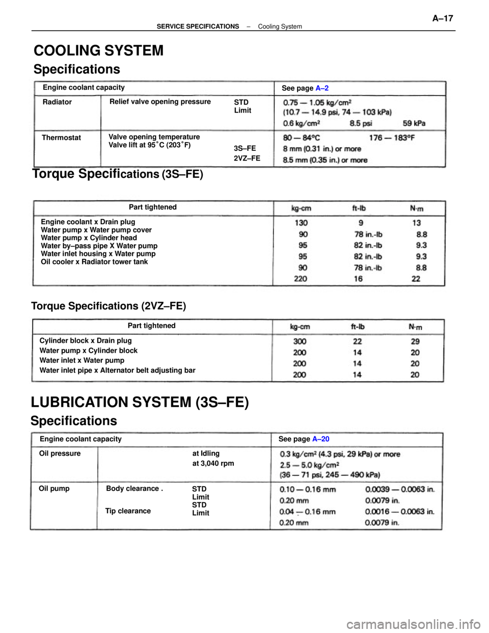
Engine coolant x Drain plug
Water pump x Water pump cover
Water pump x Cylinder head
Water by±pass pipe X Water pump
Water inlet housing x Water pump
Oil cooler x Radiator tower tank
Cylinder block x Drain plug
Water pump x Cylinder block
Water inlet x Water pump
Water inlet pipe x Alternator belt adjusting bar
LUBRICATION SYSTEM (3S±FE)
SpecificationsTorque Specifi
cations (3S±FE)
COOLING SYSTEM
Specifications
Torque Specifications (2VZ±FE)
Valve opening temperature
Valve lift at 95°C (203°F) Relief valve opening pressure
Engine coolant capacityEngine coolant capacity
at Idling
at 3,040 rpm
STD
Limit
STD
Limit Body clearance .See page A±20 STD
Limit
Part tightened
Part tightenedSee page A±2
Tip clearance3S±FE
2VZ±FE
Oil pressureThermostat
Oil pumpRadiator
± SERVICE SPECIFICATIONSCooling SystemA±17