Page 871 of 2389

8. INSTALL NEW PADS
(a) Install new pad wear indicator plate to inner pad.
NINT: Be sure the arrow on the pad wear indicator
plate is pointing i n the direction of the disc rotation.
(b) (Except 2VZ±FE Engine of w/ A.B.S.)
Install the one anti±squeal shim to the each pad.
(c) (For 2VZ±FE Engine of w/ A.B.S.)
Install the two anti±squeal shims to the each pad.
HINT: Apply disc brake grease to both side of the inner
anti±squeal shim of the outside pad.
(d) Install the pads onto each support plate.
NOTICE: Do not allow oil or grease to get on the
rubbing face.
(e) Install the two anti±squeal springs.
9. INSTALL CYLINDER
(a) Draw out a small amount of brake fluid from the reser-
voir.
(b) Press in piston with a hammer handle or an equiva-
lent.
HINT: Always change the pad on one wheel at a time as
there is a possibility of the opposite piston flying out.
(c) Insert the brake cylinder carefully ±so the boot is not
wedged. 5. CHECK ROTOR DISC THICKNESS
(See step 2 on page BR±23)
6. CHECK ROTOR DISC RUNOUT
(See step 3 on page BR±23)
7. INSTALL PAD SUPPORT PLATES
± BRAKE SYSTEMFront BrakeBR±20
Page 887 of 2389
9. INSTALL CYLINDER
(a) Draw out a small amount of brake fluid from the res-
ervoir.
(b) Press in piston with a hammer handle or an equiva-
lent.
HINT: Always change the pad on one wheel at a time as
there is a possibility of the opposite piston flying out.
(c) Insert the brake cylinder carefully so the boot is not
wedged. 8. INSTALL NEW PADS
(a) Install the two anti±squeal shims to the each pad.
HINT: Apply disc brake grease to the both side of the inner
anti±squeal shim.
(b) Install the two pads so the wear indicator plate is at
the bottom side.
NOTICE: Do not allow oil or grease to get on the rub±
bing face.
(d) Install and. torque the installation
bolt.
Torque: 200 kg±cm (14 ft±Ib, 20 N±m)
10. INSTALL REAR WHEEL
11. FILL BRAKE FLUID
± BRAKE SYSTEMRear BrakeBR±36
Page 1361 of 2389

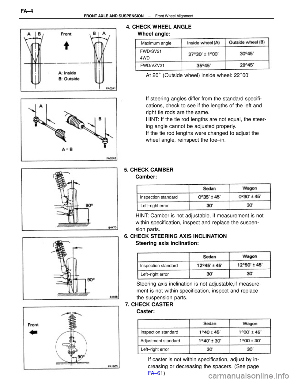
If steering angles differ from the standard specifi-
cations, check to see if the lengths of the left and
right tie rods are the same.
HINT: If the tie rod lengths are not equal, the steer-
ing angle cannot be adjusted properly.
If the tie rod lengths were changed to adjust the
wheel angle, reinspect the toe±in.
HINT: Camber is not adjustable, if measurement is not
within specification, inspect and replace the suspen-
sion parts.
6. CHECK STEERING AXIS INCLINATION
Steering axis inclination:
Steering axis inclination is not adjustable,if measure-
ment is not within specification, inspect and replace
the suspension parts.
7. CHECK CASTER
Caster:
If caster is not within specification, adjust by in-
creasing or decreasing the spacers. (See page
FA±61) At 20° (Outside wheel) inside wheel: 22°00' 4. CHECK WHEEL ANGLE
Wheel angle:
5. CHECK CAMBER
Camber:
Adjustment standard Inspection standard Inspection standard
Inspection standard FWD/SV21
4WDMaximum angle
Left±right error
Left±right error Left±right error FWD/VZV21
± FRONT AXLE AND SUSPENSIONFront Wheel AlignmentFA ± 4
Page 1362 of 2389
HINT:
wCaster changes 30' with each spacer.
wDo not install more than two spacers.
8. INSPECT TOE±IN
Measure toe±in with a toe±in gauge in the following
procedure.
(a) Bounce the vehicle up and down to stabilize the sus-
pension.
(b) Move the vehicle forward about 5 m (16.4 ft ) with the
front wheel in the straight±ahead position on a level
place.
(c) Mark the center of each rear tread and measure the
distance between the marks of the right and left tires.
(e) Measure the distance between the marks on the
front of the tires.
Inspection standard: 1
+ 2 mm (0.04 + 0.08 in.)
If necessary, adjust the toe±in.(d) Advance the vehicle until the marks on the rear
sides of the tires come to the measuring heights
of the gauge on the front side.
HINT: If the tire rolls too far, repeat from step (b).
9. ADJUST TOE±!N
(a) Remove the boot clips.
(b) Loosen the tie rod end lock nut.
± FRONT AXLE AND SUSPENSIONFront Wheel AlignmentFA ± 5
Page 1875 of 2389

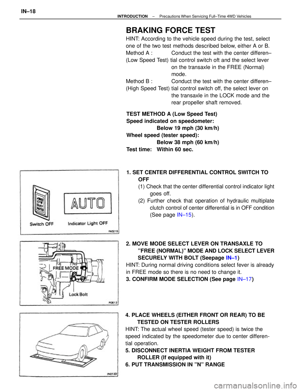
BRAKING FORCE TEST
HINT: According to the vehicle speed during the test, select
one of the two test methods described below, either A or B.
Method A : Conduct the test with the center differen±
(Low Speed Test) tial control switch oft and the select lever
on the transaxle in the FREE (Normal)
mode.
Method B : Conduct the test with the center differen±
(High Speed Test) tial control switch off, the select lever on
the transaxle in the LOCK mode and the
rear propeller shaft removed.
4. PLACE WHEELS (EITHER FRONT OR REAR) TO BE
TESTED ON TESTER ROLLERS
HINT: The actual wheel speed (tester speed) is twice the
speed indicated by the speedometer due to center differen-
tial operation.
5. DISCONNECT INERTIA WEIGHT FROM TESTER
ROLLER (If equipped with it)
6. PUT TRANSMISSION IN ºNº RANGE1. SET CENTER DIFFERENTIAL CONTROL SWITCH TO
OFF
(1) Check that the center differential control indicator light
goes off.
(2) Further check that operation of hydraulic multiplate
clutch control of center differential is in OFF condition
(See page IN±15).
2. MOVE MODE SELECT LEVER ON TRANSAXLE TO
ºFREE (NORMAL)º MODE AND LOCK SELECT LEVER
SECURELY WITH BOLT (Seepage IN±1)
HINT: During normal driving conditions select fever is already
in FREE mode so there is no need to change it.
3. CONFIRM MODE SELECTION (See page IN±17) TEST METHOD A (Low Speed Test)
Speed indicated on speedometer:
Below 19 mph (30 km/h)
Wheel speed (tester speed):
Below 38 mph (60 km/h)
Test time: Within 60 sec.
± INTRODUCTIONPrecautions When Servicing Full±Time 4WD VehiclesIN±18
Page 1914 of 2389

GENERAL MAINTENANCE
These are the maintenance and inspection items
which are considered to be the owner's responsibility,
They can be performed by the owner or he
can have then done at a service shop. These items
include those which should be checked on a daily ba-
sis, those which, in most cases, do not require
(special) tools and those which are considered to be
reasonable for the owner to perform.
Items and procedures for general maintenance are as
follows:
OUTSIDE VEHICLE
1. TIRES
(a) Check the pressure with a gauge. Adjust
if necessary.
(b) Check for cuts, damage or excessive wear.
2. WHEEL NUTS
When checking the tires, check the nuts for looseness
or for missing nuts. If necessary,
tighten them.
3. TIRE ROTATION
It is recommended that tires be rotated every
7,500 miles (12,000 km).
4. WINDSHIELD WIPER BLADES
Check for wear or cracks whenever they do not wipe
clean. Replace if necessary.
5. FLUID LEAKS
(a) Check underneath for leaking fuel, oil, water or
other fluid.
(b) If you smell gasoline fumes or notice any leak,
have the cause found and corrected.
6. DOORS AND ENGINE HOOD
(a) Check that all doors including the trunk lid and
back door operate smoothly, and that all
latches lock securely.
(b) Check that the engine hood secondary latch se-
cures the hood from opening when the prima-
ry latch is released.
INSIDE VEHICLE
7. LIGHTS
(a) Check that the headlights, stop lights, taillights,
turn signal lights, and other
lights are all working.
(b) Check the headlight aiming.8. WARNING LIGHTS AND BUZZERS
Check that all warning lights and buzzers func-
tion properly.
9. HORN
Check that it is working.
10. WINDSHIELD GLASS
Check for scratches, pits or abrasions.
11. WINDSHIELD WIPER AND WASHER
(a) Check operation of the wipers and washer.
(b) Check that the wipers do not streak.
12. WINDSHIELD DEFROSTER
Check that air comes out from the defroster out-
let when operating the heater or air conditioner
at defroster mode.
13. REAR VIEW MIRROR
Check that it is mounted securely.
14. SUN VISORS
Check that they move freely and are mounted
securely.
15. STEERING WHEEL
Check that it has the specified freeplay. Be alert
for changes in steering condition, such as hard
steering, excessive freeplay or strange noise.
16. SEATS
(a) Check that all front seat controls such as
seat adjusters, seatback recliner, etc.
operate smoothly.
(b) Check that a11 latches lock securely in
any position.
(c) Check that the locks hold securely in any
latched position.
(d) Check that the head restraints move up
and down smoothly and that the locks
hold securely in any latched position.
(e) For folding±down rear seat backs, check
that the latches lock securely.
17. SEAT BELTS
(a) Check that the seat belt system such as
buckles, retractors and anchors operate
properly and smoothly.
(b) Check that the belt webbing is not cut,
frayed, worn or damaged.
± MAINTENANCEGeneral MaintenanceMA±16
Page 2150 of 2389

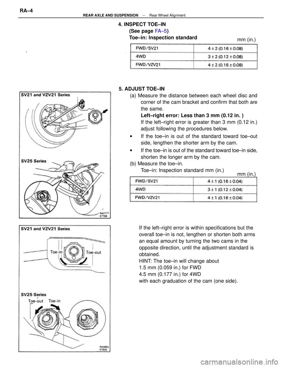
5. ADJUST TOE±IN
(a) Measure the distance between each wheel disc and
corner of the cam bracket and confirm that both are
the same.
Left±right error: Less than 3 mm (0.12 in. )
If the left±right error is greater than 3 mm (0.12 in.)
adjust following the procedures below.
wIf the toe±in is out of the standard toward toe±out
side, lengthen the shorter arm by the cam.
wIf the toe±in is out of the standard toward toe±in side,
shorten the longer arm by the cam.
(b) Measure the toe±in.
Toe±in: Inspection standard mm (in.)
If the left±right error is within specifications but the
overall toe±in is not, lengthen or shorten both arms
an equal amount by turning the two cams in the
opposite direction, until the adjustment standard is
obtained.
HINT: The toe±in will change about
1.5 mm (0.059 in.) for FWD
4.5 mm (0.177 in.) for 4WD
with each graduation of the cam (one side). 4. INSPECT TOE±IN
(See page FA ± 5)
Toe±in: Inspection standard
mm (in.) mm (in.)
± REAR AXLE AND SUSPENSIONRear Wheel AlignmentRA±4
Page 2213 of 2389
Front and rear brake
Pad thickness
Disc thickness
Disc runout
Parking brake
Lining thickness
Drum inside diameter
Front axle and suspension
Ball joint vertical play
Steering wheel freeplay
Torque specifications
Front seat mount bolts
Strut/stabilizer bar bracket x Body
Engine mounting center member x Body
Front suspension lower crossmember x Body
Rear suspension lower crossmember x Body
MAINTENANCE
Engine
Engine oil capacity (Drain and refill with oil fitter change)
Gap
Firing order
Valve clearance Coolant capacity 1w/ Heater) Drive belt tension
Alternator
Spark plug
Type
Chassis
PS pump
± SERVICE SPECIFICATIONSMaintenanceA±2