Page 1163 of 2389

INSPECTION OF EXHAUST PIPE
ASSEMBLY
CHECK CONNECTIONS FOR LOOSENESS OR DAMAGE
REPLACEMENT OF CATALYTIC
CONVERTERS
1. REMOVE CONVERTERS
(a) Jack up the vehicle.
(b) Check that the converter is cool.
(e) Remove the suspension lower crossmember.
(See page EM±44)
(d) Remove the front exhaust pipe (Sub±converter).
wLoosen the bolt, and disconnect the clamp the
exhaust pipe bracket.
wRemove the three nuts, and remove the exhaust pipe. Remove
the three nuts, and remove the exhaust pipe. Remove the gas-
ket.
(e) Remove the two bolts, two nuts and two converter stays.
(f) Remove the three bolts, two nuts, gasket, retainer, cushion and
main converter.
(g) Remove the eight bolts and two heat insulators from the main
converter.
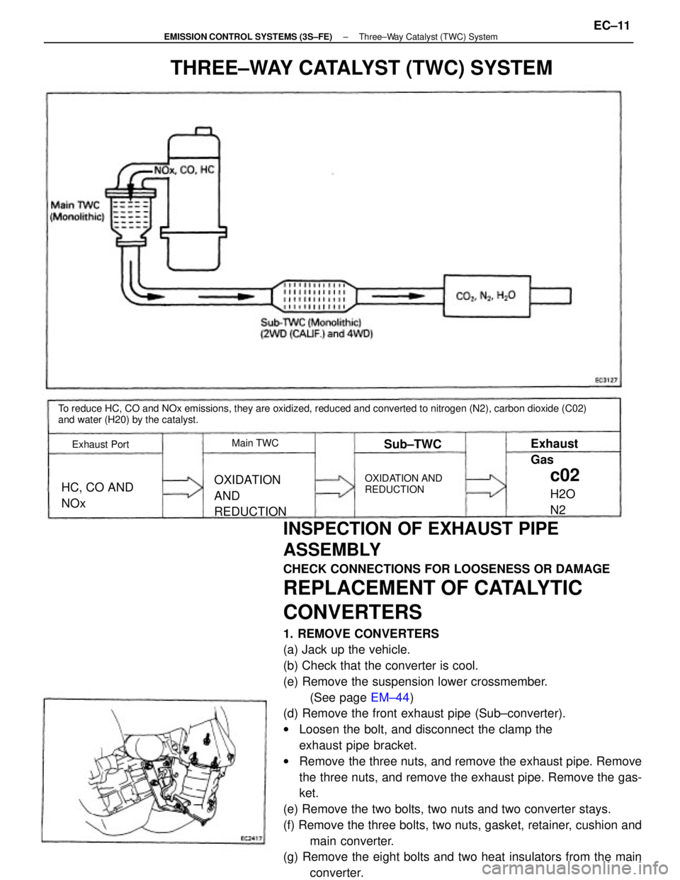
To reduce HC, CO and NOx emissions, they are oxidized, reduced and converted to nitrogen (N2), carbon dioxide (C02)
and water (H20) by the catalyst.
THREE±WAY CATALYST (TWC) SYSTEM
OXIDATION
AND
REDUCTIONOXIDATION AND
REDUCTIONHC, CO AND
NOx
Exhaust Port
c02
H2O
N2 Exhaust
Gas
Main TWCSub±TWC
± EMISSION CONTROL SYSTEMS (3S±FE)Three±Way Catalyst (TWC) SystemEC±11
Page 1176 of 2389
INSPECTION OF EXHAUST PIPE
ASSEMBLY
1. CHECK CONNECTIONS FOR LOOSENESS OR
DAMAGE
2. CHECK CLAMPS FOR WEAKNESS, CRACKS OR
DAMAGE
INSPECTION OF CATALYTIC
CONVERTER
CHECK FOR DENTS OR DAMAGE
If any part of protector is damaged or dented to the extent
that it contacts the converter, repair or replace it.
To reduce HC, CO and NOx emissions, they are oxidized, reduced and converted to nitrogen (NO, carbon dioxide (C02)
and water (H20) by the catalyst.
THREE±WAY CATALYST (TWC) SYSTEM
OXIDATION
AND
REDUCTIONOXIDATION
AND
REDUCTION HC, CO AND
NOxExhaust Gas
Exhaust Port
C02
H2O
N
2
Main TWC
Sub±TWC
± EMISSION CONTROL SYSTEMS (2VZ±FE)Three±Way Catalyst (TWC) SystemEC±24
Page 1177 of 2389
REPLACEMENT OF CATALYTIC
CONVERTER
1. REMOVE CONVERTER
(a) Jack up the vehicle.
(b) Check that the converter is cool.
(c) Remove the four bolts and nuts holding the pipes to the con-
verter.
(d) Remove the converter and two gaskets.
2. REINSTALL CONVERTER
(a) Place new two gaskets on the front and rear pipes.
(b) Install the converter with the bolts and nuts. Torque the bolts
and nuts. ,
Torque: 440 kg±cm (32 ft±Ib, 43 N±m)
INSPECTION OF HEAT INSULATOR
1. CHECK HEAT INSULATOR FOR DAMAGE
2. CHECK FOR ADEQUATE CLEARANCE BETWEEN
CATALYTIC CONVERTER AND HEAT INSULATOR
± EMISSION CONTROL SYSTEMS (2VZ±FE)Three±Way Catalyst (TWC) SystemEC±25
Page 1226 of 2389

REMOVAL OF CYLINDER HEAD
(See page EM±48)
1. DISCONNECT CABLE FROM NEGATIVE TERMINAL
OF BATTERY
2. DRAIN ENGINE COOLANT (See page CO±4)
3. (A/T)
DISCONNECT THROTTLE CABLE AND BRACKET FROM
THROTTLE BODY
4. DISCONNECT ACCELERATOR CABLE AND BRACKET
FROM THROTTLE BODY AND AIR INTAKE CHAMBER
5. REMOVE CRUISE CONTROL ACTUATOR
(See step 9 on page EM±108)
6. REMOVE AIR CLEANER HOSE
7. REMOVE ALTERNATOR (See page CH±6)
8. REMOVE OIL PRESSURE SWITCH, ENGINE HANGERS
AND ALTERNATOR UPPER BRACKET
9. RAISE VEHICLE
NOTICE: Be sure the vehicle is securely supported.
10. REMOVE RH FRONT WHEEL
11. REMOVE ENGINE RH UNDER COVER
12. REMOVE SUSPENSION LOWER CROSSMEMBER
(See step 20 on page EM±109)
13. DISCONNECT FRONT EXHAUST PIPE FROM
CATALYTIC CONVERTER
(See step 25 on page EM±110)
14. REMOVE EXHAUST MANIFOLD AND CATALYTIC
CONVERTER ASSEMBLY
(a) Disconnect the oxygen sensor connector(s).
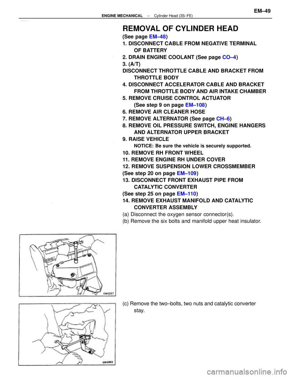
(b) Remove the six bolts and manifold upper heat insulator.
(c) Remove the two±bolts, two nuts and catalytic converter
stay.
± ENGINE MECHANICALCylinder Head (3S±FE)EM±49
Page 1227 of 2389
17. REMOVE WATER OUTLET
(a) Disconnect the following connectors and hoses:
(1) Water temperature sender gauge connector
(2) Water temperature sensor connector
(3) Cold start injector time switch connector
(4) Radiator upper hose
(5) Water hoses
(6) Emission control vacuum hoses
(b) Remove the two bolts, water outlet and gasket.
18. REMOVE WATER BY±PASS PIPE
(a) Disconnect the water hoses.
(b) Remove the two bolts, two nuts, water by±pass pipe, gasket
and O±ring. 15. SEPARATE EXHAUST MANIFOLD AND CATALYTIC
CONVERTER
Remove the following parts:
(1) Five bolts
(2) Manifold lower heat insulator
(3) Eight bolts
(4) Two catalytic converter heat insulators
(5) Three bolts and two nuts
(6) Exhaust manifold
(7) Gasket
(8) Retainer
(9) Cushion
(10) Catalytic converter
16. REMOVE DISTRIBUTOR (Seepage IG±13) (d) Remove the six nuts, the exhaust manifold and catalytic
converter assembly.
± ENGINE MECHANICALCylinder Head (3S±FE)EM±50
Page 1249 of 2389

17. INSTALL WATER OUTLET
(a) Install a new gasket and the water outlet with the two bolts.
Torque: 150 kg±cm (11 ft±lb, 15 N±m)
(b) Connect the following hoses and connectors:
(1) Radiator upper hose
(2) Water hose
(3) Emission control vacuum hoses
(4) Water temperature sender gauge connector
(5) Water temperature sensor connector
(6) Cold start injector time switch connector
18. INSTALL DISTRIBUTOR
(See steps 1 and 4 on page IG±16)
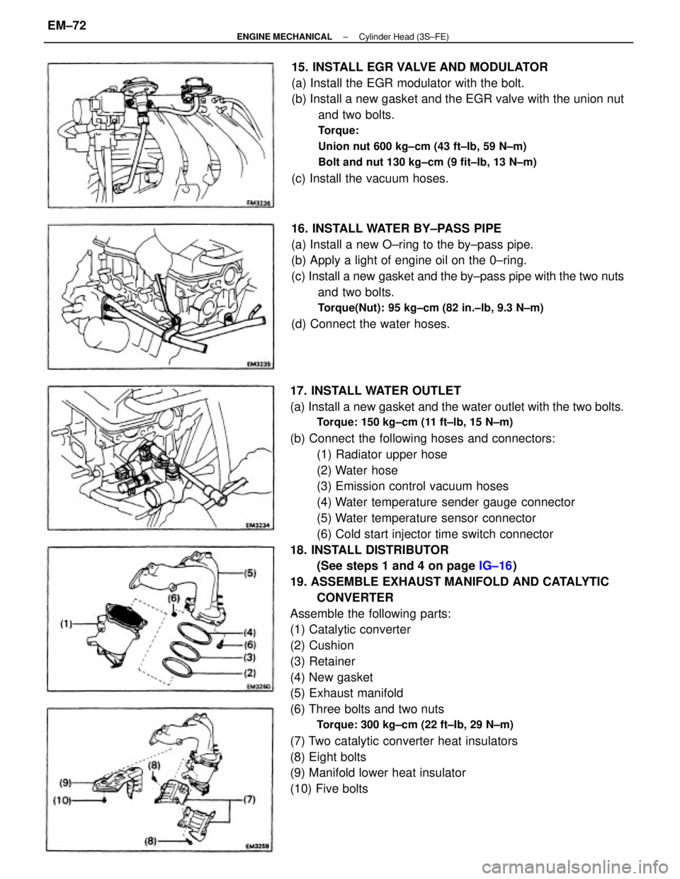
19. ASSEMBLE EXHAUST MANIFOLD AND CATALYTIC
CONVERTER
Assemble the following parts:
(1) Catalytic converter
(2) Cushion
(3) Retainer
(4) New gasket
(5) Exhaust manifold
(6) Three bolts and two nuts
Torque: 300 kg±cm (22 ft±Ib, 29 N±m)
(7) Two catalytic converter heat insulators
(8) Eight bolts
(9) Manifold lower heat insulator
(10) Five bolts15. INSTALL EGR VALVE AND MODULATOR
(a) Install the EGR modulator with the bolt.
(b) Install a new gasket and the EGR valve with the union nut
and two bolts.
Torque:
Union nut 600 kg±cm (43 ft±Ib, 59 N±m)
Bolt and nut 130 kg±cm (9 fit±Ib, 13 N±m)
(c) Install the vacuum hoses.
16. INSTALL WATER BY±PASS PIPE
(a) Install a new O±ring to the by±pass pipe.
(b) Apply a light of engine oil on the 0±ring.
(c) Install a new gasket and the by±pass pipe with the two nuts
and two bolts.
Torque(Nut): 95 kg±cm (82 in.±lb, 9.3 N±m)
(d) Connect the water hoses.
± ENGINE MECHANICALCylinder Head (3S±FE)EM±72
Page 1250 of 2389
21. CONNECT FRONT EXHAUST PIPE TO CATALYTIC
CONVERTER
(See step 12 on page EM±136)
22. INSTALL SUSPENSION LOWER CROSSMEMBER
(See step 17 on page EM±136)
23. INSTALL ENGINE RH UNDER COVER
24. INSTALL RH FRONT WHEEL
25. LOWER VEHICLE(d) Install the manifold lower heat insulator with the six
bolts.
(e) Connect the oxygen sensor connector(s). (b) Install the exhaust manifold and catalytic converter as-
sembly with new six nuts.
Torque: 500 kg±cm (37 ft±Ib, 48 N±m)
20. INSTALL EXHAUST MANIFOLD AND CATALYTIC
CONVERTER ASSEMBLY
(a) Install a gasket.
(c) Install the catalytic converter stay with the two bolts and
two nuts.
± ENGINE MECHANICALCylinder Head (3S±FE)EM±73
Page 1861 of 2389

PRECAUTIONS FOR VEHICLES EQUIPPED WITH A
CATALYTIC CONVERTER
CAUTION: If large amounts of unburned gasoline flow into the converter, it may overheat
and create a fire hazard. To prevent this, observe the following precautions and
explain them to your customer.
1. Use only unleaded gasoline.
2. Avoid prolonged idling.
Avoid running the engine at idle speed for more than 20
minutes.
3. Avoid spark jump test.
(a) Spark jump test only when absolutely necessary. Perform this test as rapidly as pos-
sible.
(b) While testing, never race the engine.
4. Avoid prolonged engine compression measurement.
Engine compression tests must be made as rapidly as possible.
5. Do not run engine when fuel tank is nearly empty.
This may cause the engine to misfire and create an extra
load on the converter.
6. Avoid coasting with ignition turned off and prolonged braking.
7. Do not dispose of used catalyst along with parts contaminated with gasoline or oil.(f) When steam cleaning an engine, protect the distribu-
tor, air filter and VCV from water.
(g) Never use an impact wrench to remove or install tem-
perature switches or temperature sensors.
(h) When checking continuity at the wire connector, insert
the tester probe carefully to prevent terminals from
bending.
(i) When using a vacuum gauge, never force the hose
onto a connector that is too large. Use a step±down
adapter instead. Once the hose has been stretched,
it may leak.
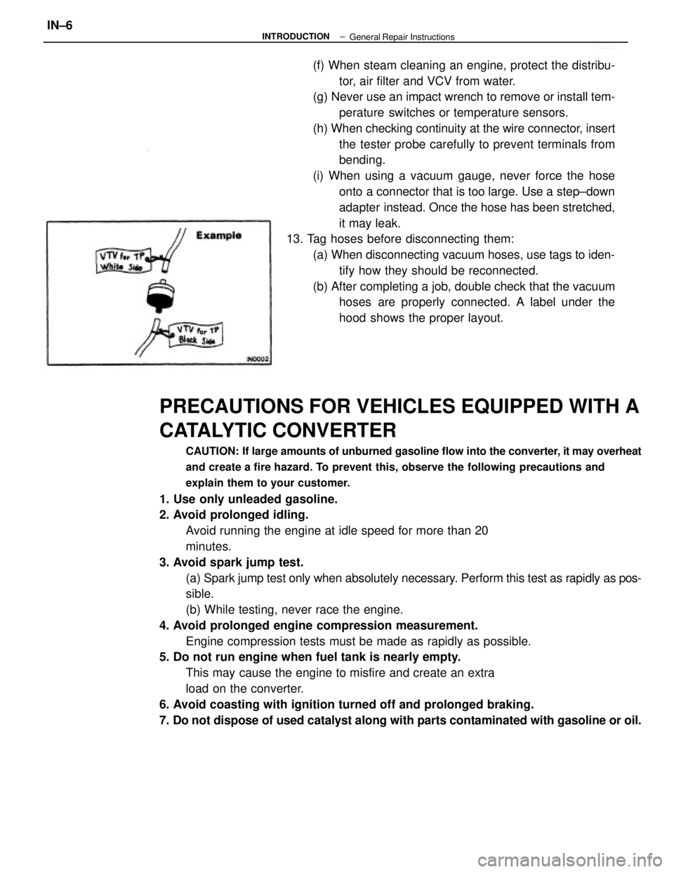
13. Tag hoses before disconnecting them:
(a) When disconnecting vacuum hoses, use tags to iden-
tify how they should be reconnected.
(b) After completing a job, double check that the vacuum
hoses are properly connected. A label under the
hood shows the proper layout.
± INTRODUCTIONIN±6General Repair Instructions