Page 1097 of 2389
2. CONNECT COLD START INJECTOR TUBE
(a) Connect the injector tube to clamp.
(b) Connect the injector tube with two new gaskets and the
union bolt.
Torque: 200 kg±cm (14 ft±Ib, 20 N±m)
3. CONNECT COLD START INJECTOR CONNECTOR
4. CONNECT CABLE TO NEGATIVE TERMINAL OF
BATTERY
5. CHECK FOR FUEL LEAKAGE (See page FI±9)
INSTALLATION OF COLD START
INJECTOR
1. INSTALL COLD START INJECTOR
Install a new gasket and the injector with the two bolts.
Torque: 55 kg±cm (48 in.±Ib, 5.4 N±m)
± EFI SYSTEMFuel System (Cold Start Injector (2VZ±FE))FI±83
Page 1103 of 2389
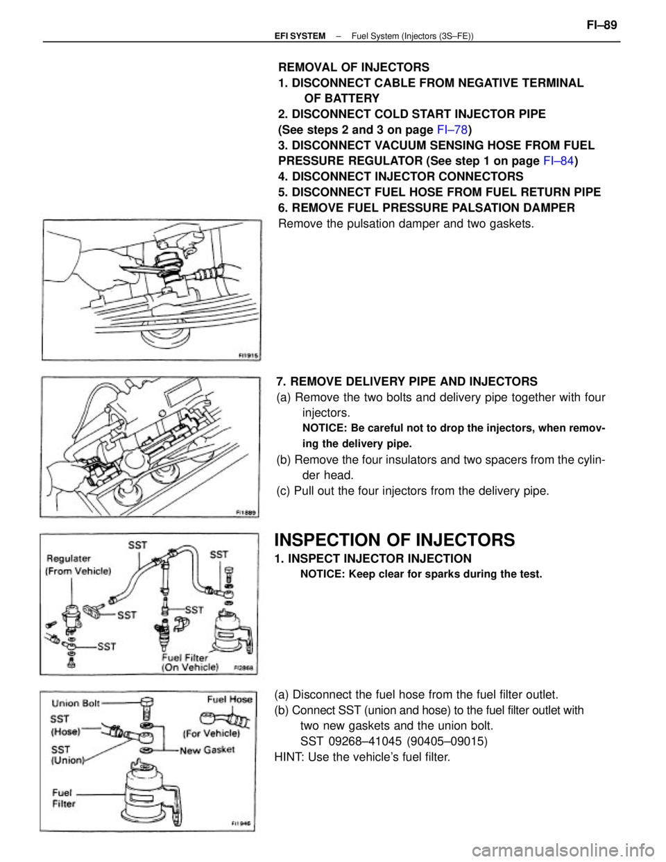
REMOVAL OF INJECTORS
1. DISCONNECT CABLE FROM NEGATIVE TERMINAL
OF BATTERY
2. DISCONNECT COLD START INJECTOR PIPE
(See steps 2 and 3 on page FI±78)
3. DISCONNECT VACUUM SENSING HOSE FROM FUEL
PRESSURE REGULATOR (See step 1 on page FI±84)
4. DISCONNECT INJECTOR CONNECTORS
5. DISCONNECT FUEL HOSE FROM FUEL RETURN PIPE
6. REMOVE FUEL PRESSURE PALSATION DAMPER
Remove the pulsation damper and two gaskets.
7. REMOVE DELIVERY PIPE AND INJECTORS
(a) Remove the two bolts and delivery pipe together with four
injectors.
NOTICE: Be careful not to drop the injectors, when remov-
ing the delivery pipe.
(b) Remove the four insulators and two spacers from the cylin-
der head.
(c) Pull out the four injectors from the delivery pipe.
(a) Disconnect the fuel hose from the fuel filter outlet.
(b) Connect SST (union and hose) to the fuel filter outlet with
two new gaskets and the union bolt.
SST 09268±41045 (90405±09015)
HINT: Use the vehicle's fuel filter.
INSPECTION OF INJECTORS
1. INSPECT INJECTOR INJECTION
NOTICE: Keep clear for sparks during the test.
± EFI SYSTEMFuel System (Injectors (3S±FE))FI±89
Page 1104 of 2389
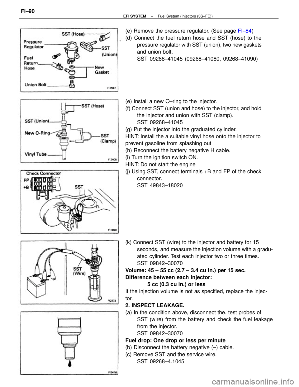
(k) Connect SST (wire) to the injector and battery for 15
seconds, and measure the injection volume with a gradu-
ated cylinder. Test each injector two or three times.
SST 09842±30070
Volume: 45 ± 55 cc (2.7 ± 3.4 cu in.) per 15 sec.
Difference between each injector:
5 cc (0.3 cu in.) or less
If the injection volume is not as specified, replace the injec-
tor.
2. INSPECT LEAKAGE.
(a) In the condition above, disconnect the. test probes of
SST (wire) from the battery and check the fuel leakage
from the injector.
SST 09842±30070
Fuel drop: One drop or less per minute
(b) Disconnect the battery negative (±) cable.
(c) Remove SST and the service wire.
SST 09268±4.1045 (e) Install a new O±ring to the injector.
(f) Connect SST (union and hose) to the injector, and hold
the injector and union with SST (clamp).
SST 09268±41045
(g) Put the injector into the graduated cylinder.
HINT: Install the a suitable vinyl hose onto the injector to
prevent gasoline from splashing out
(h) Reconnect the battery negative H cable.
(i) Turn the ignition switch ON.
HINT: Do not start the engine
(j) Using SST, connect terminals +B and FP of the check
connector.
SST 49843±18020 (e) Remove the pressure regulator. (See page FI±84)
(d) Connect the fuel return hose and SST (hose) to the
pressure regulator with SST (union), two new gaskets
and union bolt.
SST 09268±41045 (09268±41080, 09268±41090)
± EFI SYSTEMFuel System (Injectors (3S±FE))FI±90
Page 1106 of 2389
3. CONNECT FUEL RETURN HOSE
4. CONNECT INJECTOR CONNECTORS
5. CONNECT VACUUM SENSING HOSE
6. CONNECT COLD START INJECTOR PIPE
(See steps 2 and 3 on page FI±80)
7. CONNECT CABLE TO NEGATIVE TERMINAL OF
BATTERY 2. INSTALL FUEL PRESSURE PULSATION DAMPER
Install a new gasket, the fuel hose, a new gasket and the
pulsation damper.
± EFI SYSTEMFuel System (Injectors (3S±FE))FI±92
Page 1108 of 2389
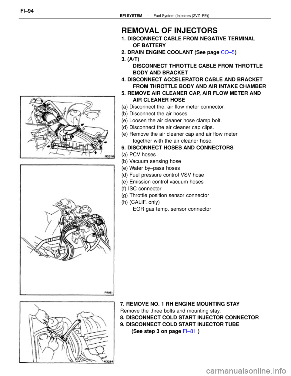
REMOVAL OF INJECTORS
1. DISCONNECT CABLE FROM NEGATIVE TERMINAL
OF BATTERY
2. DRAIN ENGINE COOLANT (See page CO±5)
3. (A/T)
DISCONNECT THROTTLE CABLE FROM THROTTLE
BODY AND BRACKET
4. DISCONNECT ACCELERATOR CABLE AND BRACKET
FROM THROTTLE BODY AND AIR INTAKE CHAMBER
5. REMOVE AIR CLEANER CAP, AIR FLOW METER AND
AIR CLEANER HOSE
(a) Disconnect the. air flow meter connector.
(b) Disconnect the air hoses.
(e) Loosen the air cleaner hose clamp bolt.
(d) Disconnect the air cleaner cap clips.
(e) Remove the air cleaner cap and air flow meter
together with the air cleaner hose.
6. DISCONNECT HOSES AND CONNECTORS
(a) PCV hoses
(b) Vacuum sensing hose
(e) Water by±pass hoses
(d) Fuel pressure control VSV hose
(e) Emission control vacuum hoses
(f) ISC connector
(g) Throttle position sensor connector
(h) (CALIF. only)
EGR gas temp. sensor connector
7. REMOVE NO. 1 RH ENGINE MOUNTING STAY
Remove the three bolts and mounting stay.
8. DISCONNECT COLD START INJECTOR CONNECTOR
9. DISCONNECT COLD START INJECTOR TUBE
(See step 3 on page FI±81 )
± EFI SYSTEMFuel System (Injectors (2VZ±FE))FI±94
Page 1111 of 2389
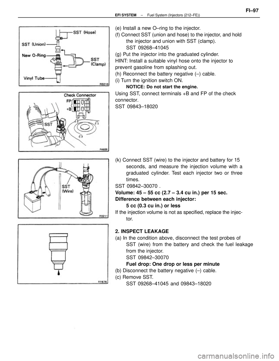
(e) Install a new O±ring to the injector.
(f) Connect SST (union and hose) to the injector, and hold
the injector and union with SST (clamp).
SST 09268±41045
(g) Put the injector into the graduated cylinder.
HINT: Install a suitable vinyl hose onto the injector to
prevent gasoline from splashing out.
(h) Reconnect the battery negative (±) cable.
(i) Turn the ignition switch ON.
NOTICE: Do not start the engine.
Using SST, connect terminals +B and FP of the check
connector.
SST 09843±18020
2. INSPECT LEAKAGE
(a) In the condition above, disconnect the test probes of
SST (wire) from the battery and check the fuel leakage
from the injector.
SST 09842±30070
Fuel drop: One drop or less per minute
(b) Disconnect the battery negative (±) cable.
(c) Remove SST.
SST 09268±41045 and 09843±18020 (k) Connect SST (wire) to the injector and battery for 15
seconds, and measure the injection volume with a
graduated cylinder. Test each injector two or three
times.
SST 09842±30070 .
Volume: 45 ± 55 cc (2.7 ± 3.4 cu in.) per 15 sec.
Difference between each injector:
5 cc (0.3 cu in.) or less
If the injection volume is not as specified, replace the injec-
tor.
± EFI SYSTEMFuel System (Injectors (212±FE))FI±97
Page 1114 of 2389
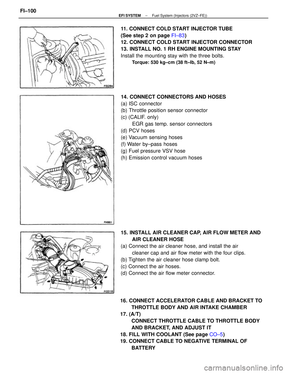
16. CONNECT ACCELERATOR CABLE AND BRACKET TO
THROTTLE BODY AND AIR INTAKE CHAMBER
17. (A/T)
CONNECT THROTTLE CABLE TO THROTTLE BODY
AND BRACKET, AND ADJUST IT
18. FILL WITH COOLANT (See page CO±5)
19. CONNECT CABLE TO NEGATIVE TERMINAL OF
BATTERY 14. CONNECT CONNECTORS AND HOSES
(a) ISC connector
(b) Throttle position sensor connector
(c) (CALIF. only)
EGR gas temp. sensor connectors
(d) PCV hoses
(e) Vacuum sensing hoses
(f) Water by±pass hoses
(g) Fuel pressure VSV hose
(h) Emission control vacuum hoses
15. INSTALL AIR CLEANER CAP, AIR FLOW METER AND
AIR CLEANER HOSE
(a) Connect the air cleaner hose, and install the air
cleaner cap and air flow meter with the four clips.
(b) Tighten the air cleaner hose clamp bolt.
(c) Connect the air hoses.
(d) Connect the air flow meter connector. 11. CONNECT COLD START INJECTOR TUBE
(See step 2 on page FI±83)
12. CONNECT COLD START INJECTOR CONNECTOR
13. INSTALL NO. 1 RH ENGINE MOUNTING STAY
Install the mounting stay with the three bolts.
Torque: 530 kg±cm (38 ft±Ib, 52 N±m)
± EFI SYSTEMFuel System (Injectors (2VZ±FE))FI±100
Page 1133 of 2389
INSTALLATION OF ISC VALVE
1. INSTALL ISC VALVE
(a) Install a new gasket and the ISC valve with the two bolts.
Torque: 130 kg±cm (9 ft±Ib, 13 N±m)
(b) Connect the wire harness clamp with the nut.
INSPECTION OF ISC VALVE
INSPECT ISC VALVE OPERATION
(a) Apply battery voltage to terminals 81 and B2, and while re-
peatedly grounding S1 ± S2 ± S3 ± S4 ±
S1 in sequence, check that the valve moves to¿¿rd the
closed position.
2. CONNECT TWO WATER BY±PASS HOSES AND AIR
HOSE
3. CONNECT ISC VALVE CONNECTOR
4. FILL WITH ENGINE COOLANT (See page CO±5) (b) Apply battery voltage to terminals 81 and 82, and while
repeatedly grounding S4 ± S3 S2 ± S 1 ±
S4 in sequence, check that the valve moves toward
the open position.
If operation is not as specified, replace the ISC valve. 4. REMOVE ISC VALVE
(a) Remove the nut, and disconnect the wire harness clamp.
(b) Remove the two bolts, ISC valve and gasket.
± EFI SYSTEMAir Induction System (Idle Speed Control (ISC) Valve(2VZ FE))
FI±119