Page 1317 of 2389
REMOVAL OF ENGINE
1. REMOVE BATTERY
Disconnect the grand strap.
2. DRAIN ENGINE COOLANT (See page CO±5)
3. REMOVE HOOD
4. REMOVE ENGINE UNDER COVERS
5. DRAIN ENGINE COOLANT (See page CO±5)
6. DRAIN ENGINE OIL
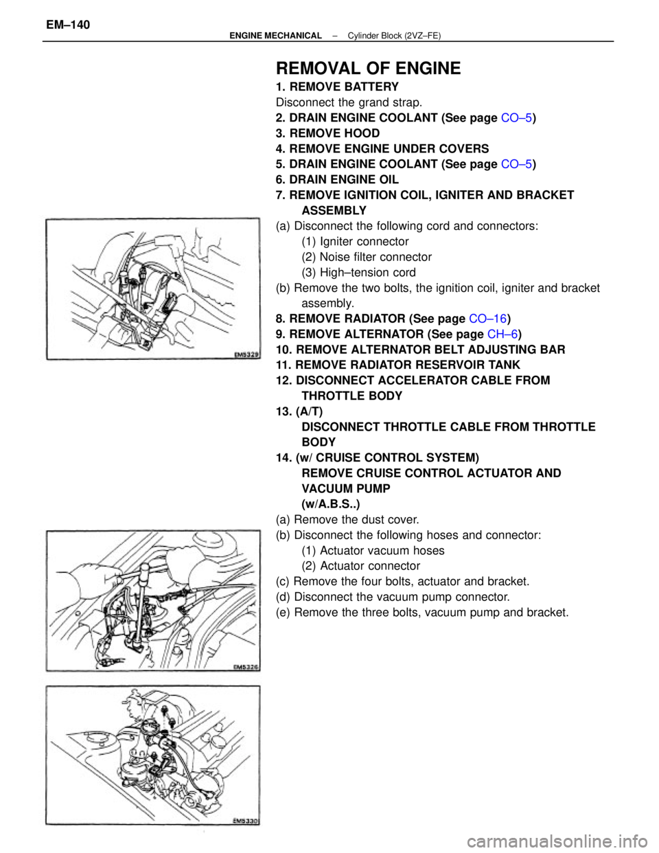
7. REMOVE IGNITION COIL, IGNITER AND BRACKET
ASSEMBLY
(a) Disconnect the following cord and connectors:
(1) Igniter connector
(2) Noise filter connector
(3) High±tension cord
(b) Remove the two bolts, the ignition coil, igniter and bracket
assembly.
8. REMOVE RADIATOR (See page CO±16)
9. REMOVE ALTERNATOR (See page CH±6)
10. REMOVE ALTERNATOR BELT ADJUSTING BAR
11. REMOVE RADIATOR RESERVOIR TANK
12. DISCONNECT ACCELERATOR CABLE FROM
THROTTLE BODY
13. (A/T)
DISCONNECT THROTTLE CABLE FROM THROTTLE
BODY
14. (w/ CRUISE CONTROL SYSTEM)
REMOVE CRUISE CONTROL ACTUATOR AND
VACUUM PUMP
(w/A.B.S..)
(a) Remove the dust cover.
(b) Disconnect the following hoses and connector:
(1) Actuator vacuum hoses
(2) Actuator connector
(c) Remove the four bolts, actuator and bracket.
(d) Disconnect the vacuum pump connector.
(e) Remove the three bolts, vacuum pump and bracket.
± ENGINE MECHANICALCylinder Block (2VZ±FE)EM±140
Page 1351 of 2389
28. (A/T)
INSTALL THROTTLE CABLE, AND ADJUST IT
29. INSTALL ACCELERATOR CABLE, AND ADJUST IT
30. INSTALL RADIATOR RESERVOIR TANK
31. INSTALL ALTERNATOR BELT ADJUSTING BAR
32. INSTALL ALTERNATOR (See page CH±15)
33. INSTALL RADIATOR (See page CO±20)
34. INSTALL IGNITION COIL, IGNITER AND BRACKET AS-
SEMBLY
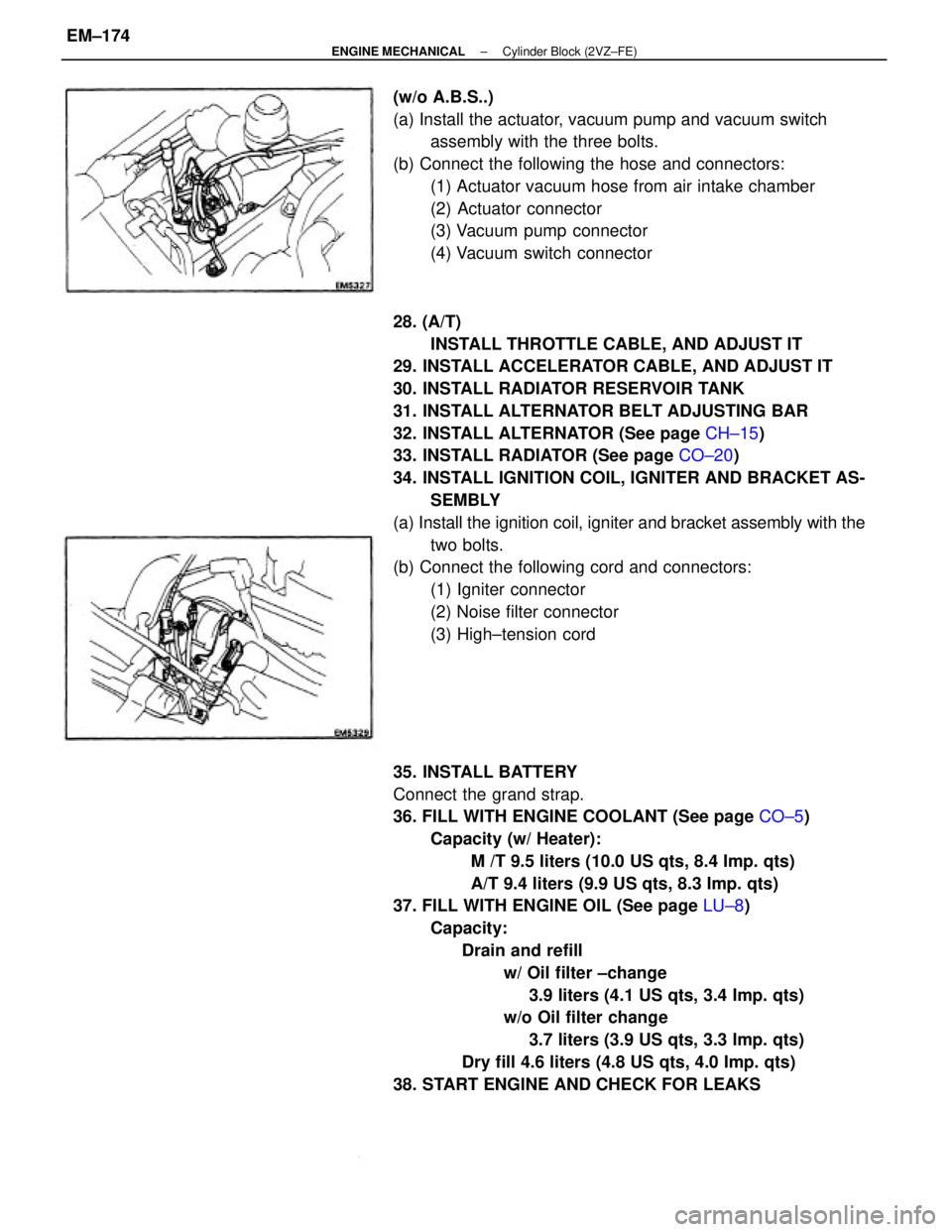
(a) Install the ignition coil, igniter and bracket assembly with the
two bolts.
(b) Connect the following cord and connectors:
(1) Igniter connector
(2) Noise filter connector
(3) High±tension cord
35. INSTALL BATTERY
Connect the grand strap.
36. FILL WITH ENGINE COOLANT (See page CO±5)
Capacity (w/ Heater):
M /T 9.5 liters (10.0 US qts, 8.4 Imp. qts)
A/T 9.4 liters (9.9 US qts, 8.3 Imp. qts)
37. FILL WITH ENGINE OIL (See page LU±8)
Capacity:
Drain and refill
w/ Oil filter ±change
3.9 liters (4.1 US qts, 3.4 Imp. qts)
w/o Oil filter change
3.7 liters (3.9 US qts, 3.3 Imp. qts)
Dry fill 4.6 liters (4.8 US qts, 4.0 Imp. qts)
38. START ENGINE AND CHECK FOR LEAKS (w/o A.B.S..)
(a) Install the actuator, vacuum pump and vacuum switch
assembly with the three bolts.
(b) Connect the following the hose and connectors:
(1) Actuator vacuum hose from air intake chamber
(2) Actuator connector
(3) Vacuum pump connector
(4) Vacuum switch connector
± ENGINE MECHANICALCylinder Block (2VZ±FE)EM±174
Page 1425 of 2389
![TOYOTA CAMRY V20 1986 Service Information To Ignition SW
IG Terminal
Fuse
Relay
SW2 SolenoidVoltmeter [A]
[B]
[C] SW1
Ohmmeter
SW
INTRODUCTION±HOW TO PERFORM FOR SYSTEM INSPECTION
A±5
6
Wire Harness Repair Manual (RM1022E)
HOW TO PERFORM FO TOYOTA CAMRY V20 1986 Service Information To Ignition SW
IG Terminal
Fuse
Relay
SW2 SolenoidVoltmeter [A]
[B]
[C] SW1
Ohmmeter
SW
INTRODUCTION±HOW TO PERFORM FOR SYSTEM INSPECTION
A±5
6
Wire Harness Repair Manual (RM1022E)
HOW TO PERFORM FO](/manual-img/14/57449/w960_57449-1424.png)
To Ignition SW
IG Terminal
Fuse
Relay
SW2 SolenoidVoltmeter [A]
[B]
[C] SW1
Ohmmeter
SW
INTRODUCTION±HOW TO PERFORM FOR SYSTEM INSPECTION
A±5
6
Wire Harness Repair Manual (RM1022E)
HOW TO PERFORM FOR SYSTEM INSPECTION
This inspection procedure is a simple troubleshooting which should be carried out on the vehicle during
system operation and is based on the assumption of system component trouble
Always inspect the trouble taking the following items into consideration:
�Ground point fault
�Open or short circuit of the wire harness
�Connector or terminal connection fault
�Fuse or fusible link fault
NOTICE:
�This is an on±vehicle inspection during system operation.
Therefore, inspect the trouble with due regard for safety.
�If connecting the battery directly, be careful not to cause a short circuit, and select the applicable
voltage.
1. Voltage Check
(a)Establish conditions in which voltage is present at the
check point.
Example:
[A] ± Ignition SW on
[B] ± Ignition SW and SW 1 on
[C] ± Ignition SW, SW 1 and Relay on (SW 2 off)
(b)Using a voltmeter, connect the negative (±) lead to a
good ground point or negative (±) battery terminal
and the positive (+) lead to the connector or
component terminal. This check can be done with a
test bulb instead of a voltmeter.
2. Continuity and Resistance Check
(a)Disconnect the battery terminal or wire so there is no
voltage between the check points.
(b)Contact the two leads of an ohmmeter to each of the
check points.
A
Page 1426 of 2389
Diode Ohmmeter
Diode Ohmmeter
Digital Type Analog Type
Bulb Ohmmeter
A±6
INTRODUCTION±HOW TO PERFORM FOR SYSTEM INSPECTION
7
Wire Harness Repair Manual (RM1022E)
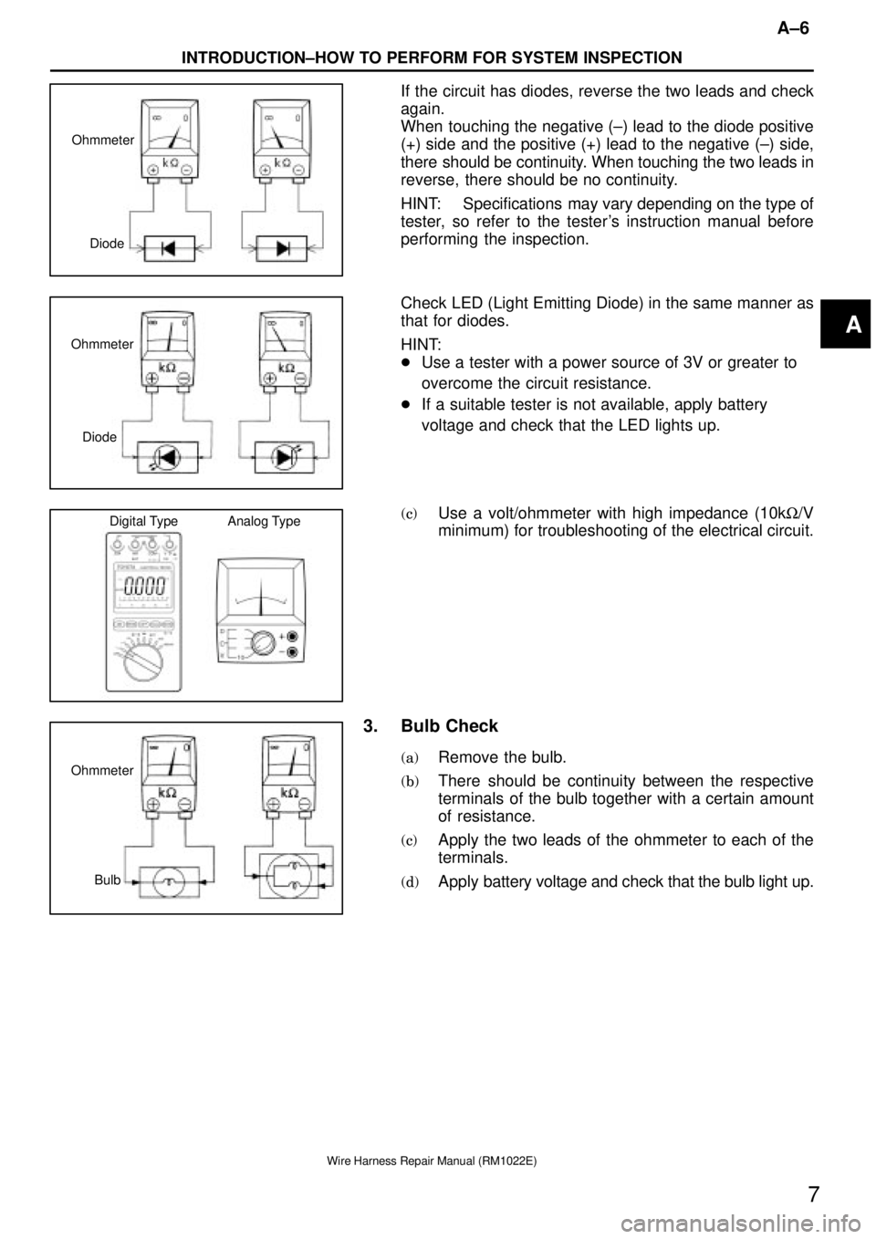
If the circuit has diodes, reverse the two leads and check
again.
When touching the negative (±) lead to the diode positive
(+) side and the positive (+) lead to the negative (±) side,
there should be continuity. When touching the two leads in
reverse, there should be no continuity.
HINT: Specifications may vary depending on the type of
tester, so refer to the tester's instruction manual before
performing the inspection.
Check LED (Light Emitting Diode) in the same manner as
that for diodes.
HINT:
�Use a tester with a power source of 3V or greater to
overcome the circuit resistance.
�If a suitable tester is not available, apply battery
voltage and check that the LED lights up.
(c)Use a volt/ohmmeter with high impedance (10kW/V
minimum) for troubleshooting of the electrical circuit.
3. Bulb Check
(a)Remove the bulb.
(b)There should be continuity between the respective
terminals of the bulb together with a certain amount
of resistance.
(c)Apply the two leads of the ohmmeter to each of the
terminals.
(d)Apply battery voltage and check that the bulb light up.
A
Page 1428 of 2389
Push
Equal Amperage Rating
A±8
INTRODUCTION±CIRCUIT PROTECTION
9
Wire Harness Repair Manual (RM1022E)
CIRCUIT PROTECTION
All electrical circuits are protected against excessive loads which might occur because of shorts or
overloads in the wiring system. Such protection is provided by a fuse, circuit breaker, or fusible link, A
short circuit may cause a fuse to blow or a circuit breaker to open.
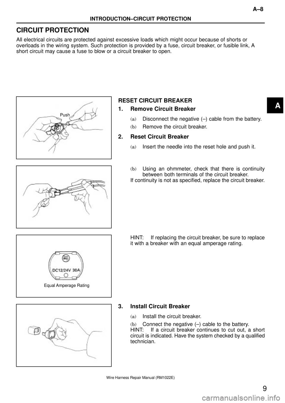
RESET CIRCUIT BREAKER
1. Remove Circuit Breaker
(a)Disconnect the negative (±) cable from the battery.
(b)Remove the circuit breaker.
2. Reset Circuit Breaker
(a)Insert the needle into the reset hole and push it.
(b)Using an ohmmeter, check that there is continuity
between both terminals of the circuit breaker.
If continuity is not as specified, replace the circuit breaker.
HINT: If replacing the circuit breaker, be sure to replace
it with a breaker with an equal amperage rating.
3. Install Circuit Breaker
(a)Install the circuit breaker.
(b)Connect the negative (±) cable to the battery.
HINT: If a circuit breaker continues to cut out, a short
circuit is indicated. Have the system checked by a qualified
technician.
A
Page 1835 of 2389
4. As some tachometers are not compatible with this igni-
tion system, we recommend that you confirm the
compatibility of your unit before use.
5. NEVER allow the tachometer test probe to touch ground
as this could damage the igniter and/or ignition coil.
6. Do not disconnect the battery when the engine is run-
ning.
7. Check that the igniter is properly grounded to the body.
PRECAUTIONS
1. Do not leave the ignition switch on for more than 10
minutes if the engine will not start.
2. (3S±FE)
When a tachometer is connected to the system, con-
nect the test probe of the tachometer to service con-
nector of the distributor.
3. (2VZ±FE)
When a tachometer is connected to the system, con-
nect the test probe of the tachometer to terminal IG E)
of the check connector.
± IGNITION SYSTEMPrecautionsIG±2
Page 1838 of 2389
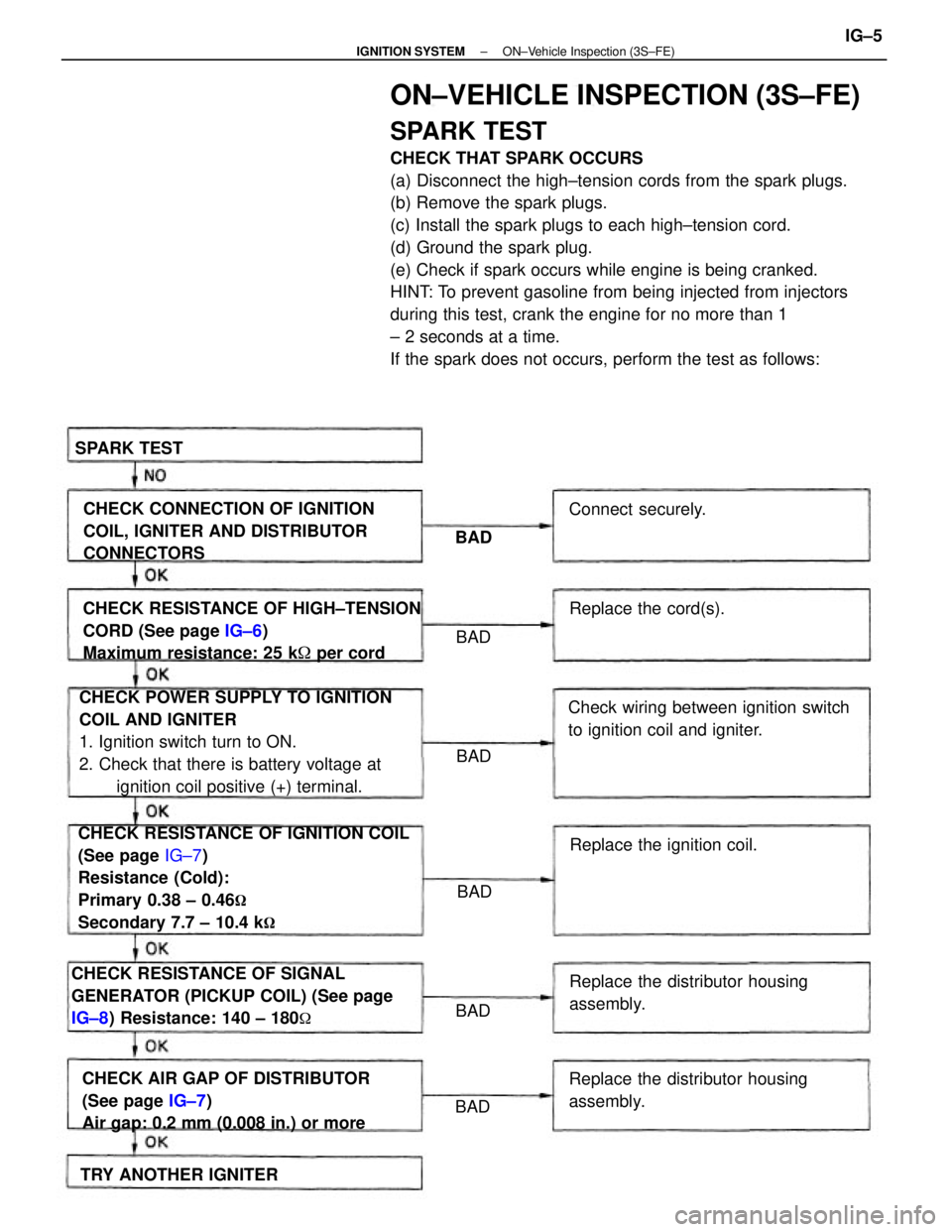
ON±VEHICLE INSPECTION (3S±FE)
SPARK TEST
CHECK THAT SPARK OCCURS
(a) Disconnect the high±tension cords from the spark plugs.
(b) Remove the spark plugs.
(c) Install the spark plugs to each high±tension cord.
(d) Ground the spark plug.
(e) Check if spark occurs while engine is being cranked.
HINT: To prevent gasoline from being injected from injectors
during this test, crank the engine for no more than 1
± 2 seconds at a time.
If the spark does not occurs, perform the test as follows:
CHECK RESISTANCE OF IGNITION COIL
(See page IG±7)
Resistance (Cold):
Primary 0.38 ± 0.46
�
Secondary 7.7 ± 10.4 k�
CHECK POWER SUPPLY TO IGNITION
COIL AND IGNITER
1. Ignition switch turn to ON.
2. Check that there is battery voltage at
ignition coil positive (+) terminal. CHECK RESISTANCE OF HIGH±TENSION
CORD (See page IG±6)
Maximum resistance: 25 k� per cord
CHECK RESISTANCE OF SIGNAL
GENERATOR (PICKUP COIL) (See page
IG±8) Resistance: 140 ± 180
�
CHECK AIR GAP OF DISTRIBUTOR
(See page IG±7)
Air gap: 0.2 mm (0.008 in.) or moreCHECK CONNECTION OF IGNITION
COIL, IGNITER AND DISTRIBUTOR
CONNECTORS
Check wiring between ignition switch
to ignition coil and igniter.
Replace the distributor housing
assembly.
Replace the distributor housing
assembly.Replace the ignition coil.
TRY ANOTHER IGNITERReplace the cord(s). Connect securely. SPARK TEST
BAD BAD
BAD
BAD BAD
BAD
± IGNITION SYSTEMON±Vehicle Inspection (3S±FE)IG±5
Page 1842 of 2389
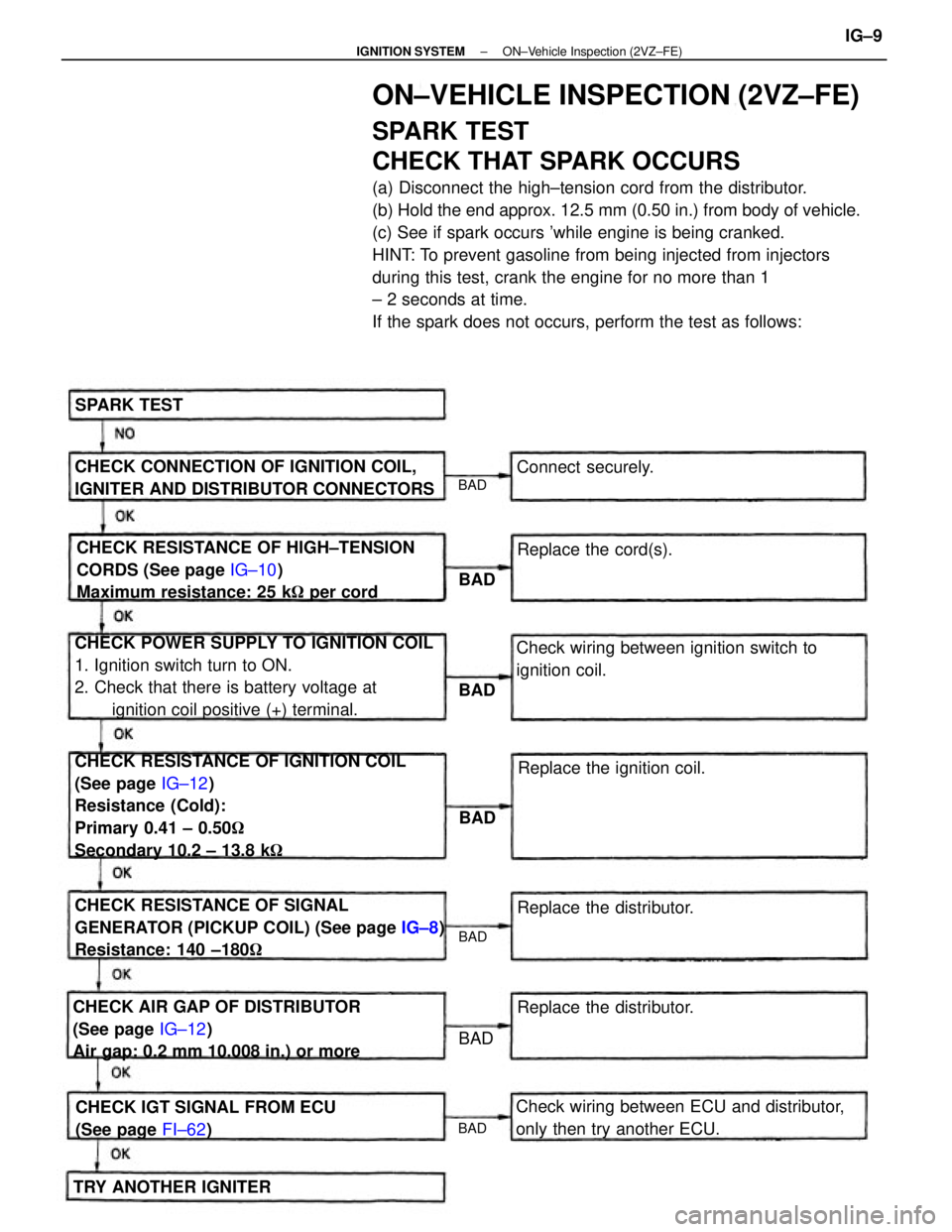
ON±VEHICLE INSPECTION (2VZ±FE)
SPARK TEST
CHECK THAT SPARK OCCURS
(a) Disconnect the high±tension cord from the distributor.
(b) Hold the end approx. 12.5 mm (0.50 in.) from body of vehicle.
(c) See if spark occurs 'while engine is being cranked.
HINT: To prevent gasoline from being injected from injectors
during this test, crank the engine for no more than 1
± 2 seconds at time.
If the spark does not occurs, perform the test as follows:
CHECK RESISTANCE OF IGNITION COIL
(See page IG±12)
Resistance (Cold):
Primary 0.41 ± 0.50�
Secondary 10.2 ± 13.8 k� CHECK POWER SUPPLY TO IGNITION COIL
1. Ignition switch turn to ON.
2. Check that there is battery voltage at
ignition coil positive (+) terminal.
CHECK RESISTANCE OF SIGNAL
GENERATOR (PICKUP COIL) (See page IG±8)
Resistance: 140 ±180� CHECK RESISTANCE OF HIGH±TENSION
CORDS (See page IG±10)
Maximum resistance: 25 k� per cord
CHECK AIR GAP OF DISTRIBUTOR
(See page IG±12)
Air gap: 0.2 mm 10.008 in.) or moreCHECK CONNECTION OF IGNITION COIL,
IGNITER AND DISTRIBUTOR CONNECTORS
Check wiring between ECU and distributor,
only then try another ECU.Check wiring between ignition switch to
ignition coil.
CHECK IGT SIGNAL FROM ECU
(See page FI±62)Replace the ignition coil.
Replace the distributor.
TRY ANOTHER IGNITERReplace the distributor. Replace the cord(s). Connect securely. SPARK TEST
BAD
BAD
BAD
BAD BAD
BAD
BAD
± IGNITION SYSTEMON±Vehicle Inspection (2VZ±FE)IG±9