Page 2322 of 2389
PERFORMANCE TEST OF STARTER
NOTICE: These tests must be performed within 3 to 5
seconds to avoid burning out the coil.
1. PERFORM PULL±IN TEST
(a) Disconnect the field coil lead wire from terminal C.
(b) Connect battery to the magnetic switch as shown.
Check that the pinion gear moves outward.
If the pinion gear does not move, replace the magnetic
switch.
2. PERFORM HOLD±IN TEST
While connected as above with the pinion gear out, discon-
nect the negative (±) lead from terminal C.
Check that the pinion gear remains out.
If the pinion gear returns inward, replace the magnetic
switch. (c) Install the field frame and armature assembly with the
two through bolts.
(d) Connect the lead wire to terminal C, and install the nut. (b) Align the protrusion of the field frame with the cutout
of the magnetic switch.
± STARTING SYSTEMStarterST±14
Page 2323 of 2389

INSTALLATION OF STARTER (3S±FE)
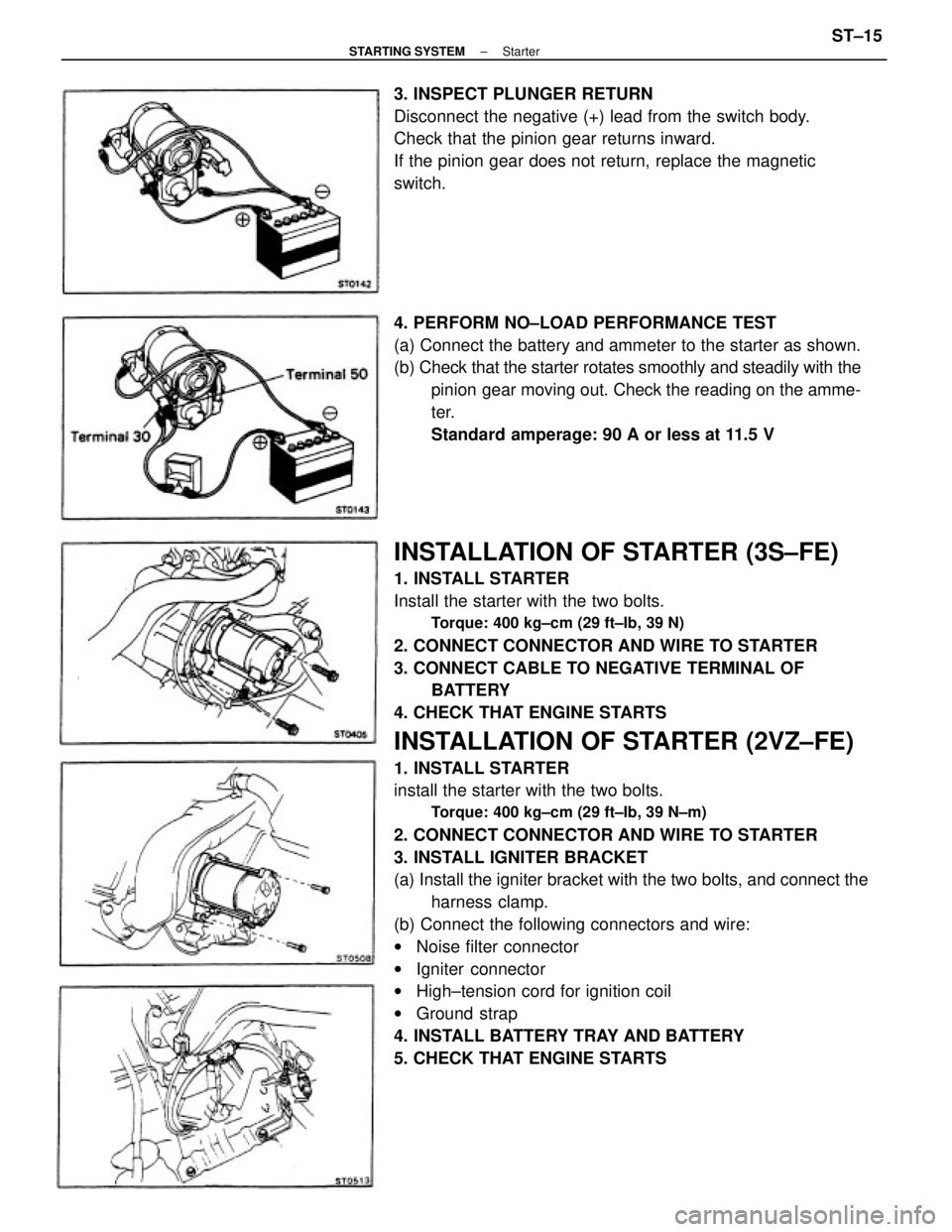
1. INSTALL STARTER
Install the starter with the two bolts.
Torque: 400 kg±cm (29 ft±Ib, 39 N)
2. CONNECT CONNECTOR AND WIRE TO STARTER
3. CONNECT CABLE TO NEGATIVE TERMINAL OF
BATTERY
4. CHECK THAT ENGINE STARTS
INSTALLATION OF STARTER (2VZ±FE)
1. INSTALL STARTER
install the starter with the two bolts.
Torque: 400 kg±cm (29 ft±Ib, 39 N±m)
2. CONNECT CONNECTOR AND WIRE TO STARTER
3. INSTALL IGNITER BRACKET
(a) Install the igniter bracket with the two bolts, and connect the
harness clamp.
(b) Connect the following connectors and wire:
wNoise filter connector
wIgniter connector
wHigh±tension cord for ignition coil
wGround strap
4. INSTALL BATTERY TRAY AND BATTERY
5. CHECK THAT ENGINE STARTS 4. PERFORM NO±LOAD PERFORMANCE TEST
(a) Connect the battery and ammeter to the starter as shown.
(b) Check that the starter rotates smoothly and steadily with the
pinion gear moving out. Check the reading on the amme-
ter.
Standard amperage: 90 A or less at 11.5 V 3. INSPECT PLUNGER RETURN
Disconnect the negative (+) lead from the switch body.
Check that the pinion gear returns inward.
If the pinion gear does not return, replace the magnetic
switch.
± STARTING SYSTEMStarterST±15
Page 2324 of 2389
1. INSPECT RELAY CONTINUITY
(a) Using an ohmmeter, check that there is continuity between
terminals 1 and 3.
(b) Check that there is no continuity between terminals 2
and 4.
If continuity is not as specified, replace the relay.
2. INSPECT RELAY OPERATION
(a) Apply battery voltage across terminals 1 and 3.
(b) Using an ohmmeter, check that there is continuity between
terminals 2 and 4.
If operation is not as specified, replace the relay.
STARTER RELAY (MT only)
INSPECTION OF STARTER RELAY
LOCATION: In the left cowl side.
CLUTCH START SWITCH (MT only)
(See page CL±4)
± STARTING SYSTEMStarter Relay (M T only)ST±16
Page 2325 of 2389
1. INSPECT RELAY CONTINUITY
(a) Using an ohmmeter, check that there is continuity between
terminals 1 and 3.
(b) Check that there is no continuity between terminals 2
and 4.
If continuity is not as specified, replace the relay.
2. INSPECT RELAY OPERATION
(a) Apply battery voltage across terminals 1 and 3.
(b) Using an ohmmeter, check that there is continuity between
terminals 2 and 4.
If operation is not as specified, replace the relay.
STARTER RELAY (MT only)
INSPECTION OF STARTER RELAY
LOCATION: In the left cowl side.
CLUTCH START SWITCH (MT only)
(See page CL±4)
± STARTING SYSTEMClutch Start Switch (M T only)ST±16